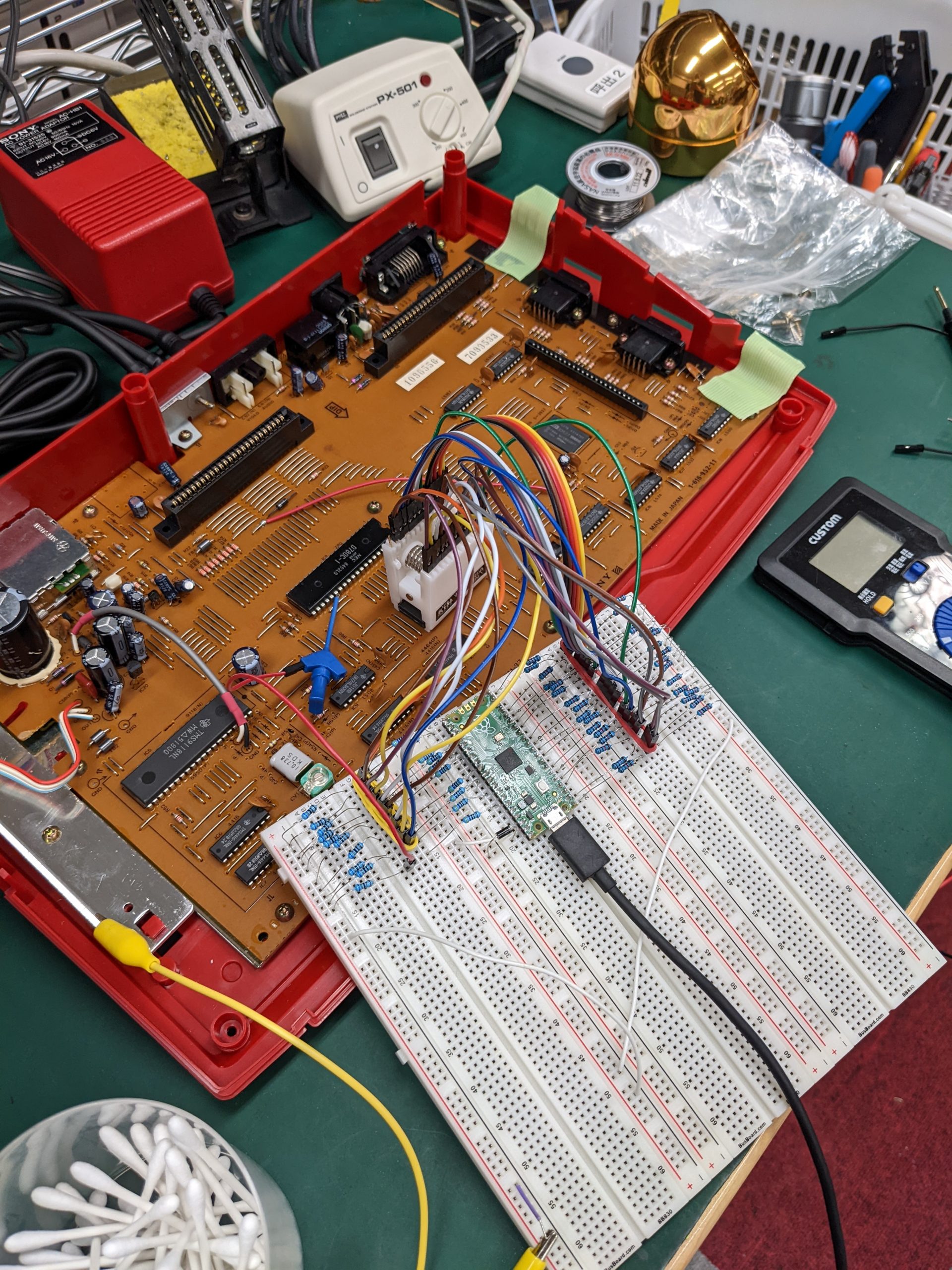
Update 2023/08/11: Testing live (powered) DRAM chips in-circuit.
Happy New Year! Hopefully with less coronavirus and less violence.
Somebody I know told me about their broken Amiga and how they had pulled out and tested every RAM/ROM/CPU chip and couldn’t find the fault, and now wanted to pull out every 74-series logic chip to test those too.
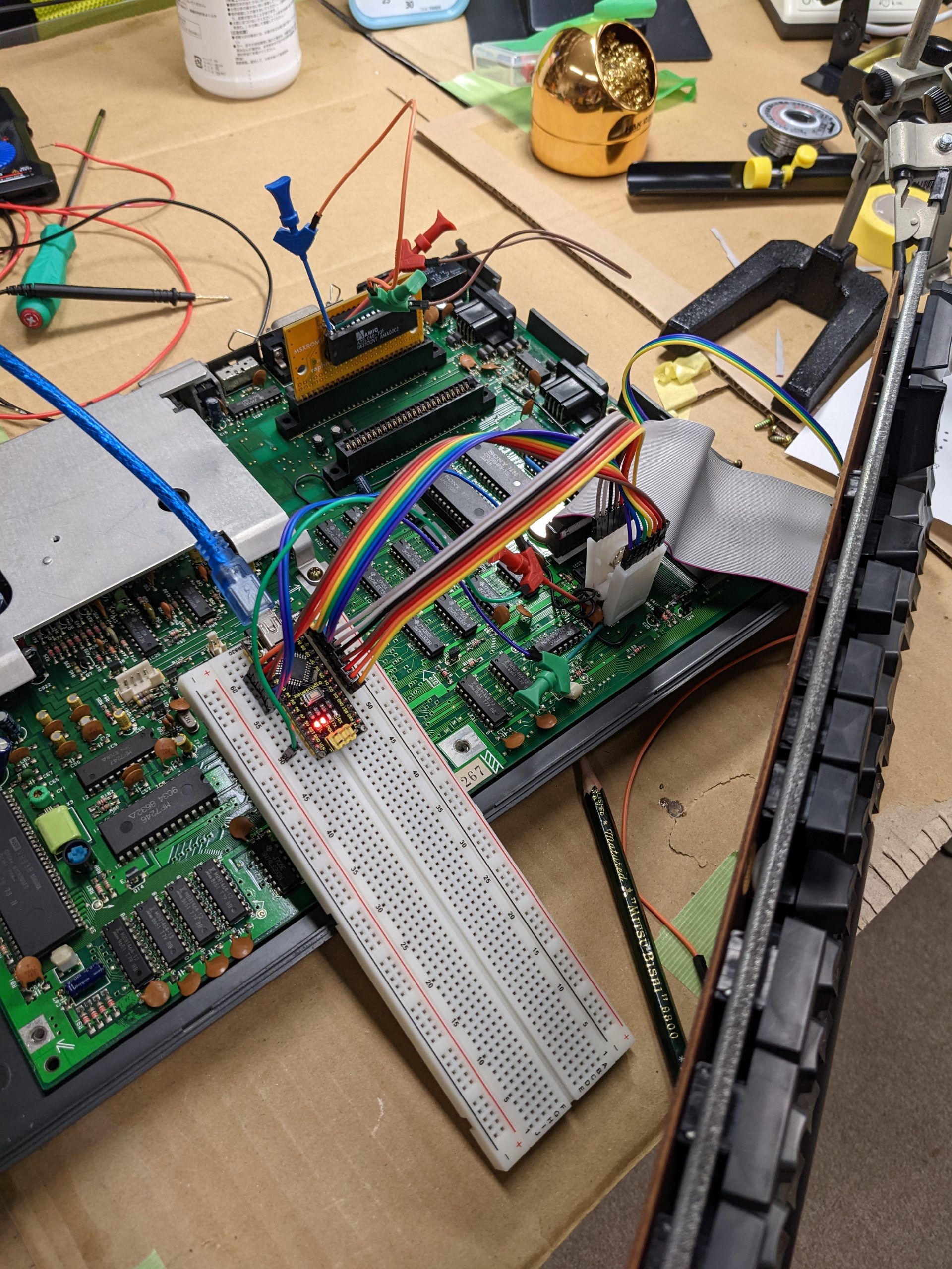
I didn’t have much to say at the time, but at some point I decided to try my hand at building an in-circuit chip tester, i.e., something that passively monitors a chip’s input and output pins while the device is running, and figures out if the chip is behaving correctly. All that is needed is an Arduino (Nano in my case) and a large IC test clip. The Arduino repeatedly samples all the pins and works out if the chip’s output pins are valid for the given inputs. This works great for simple logic chips (like NOT or AND), but not quite so well for chips with high-impedance modes.
The Arduino runs at 16 MHz, and is capable of reading in all pins in about 3 CPU cycles. The device under test would have to be slow enough (which is true for most computers considered “retro” at the time of this writing) to make this work. To avoid sampling while the inputs are changing (which is likely to show as a state that isn’t possible for a correctly functioning chip), the pins are sampled twice, and if samples 1 and 2 aren’t equal, the code samples the pins again, until they’re consistent. (Search for “WAIT_UNTIL_CONSISTENT” in the code for details.)
Note: I originally coded this for the Raspberry Pi Pico, but decided to use the Arduino instead because it’s fast enough and is 5V-tolerant.
How to use this
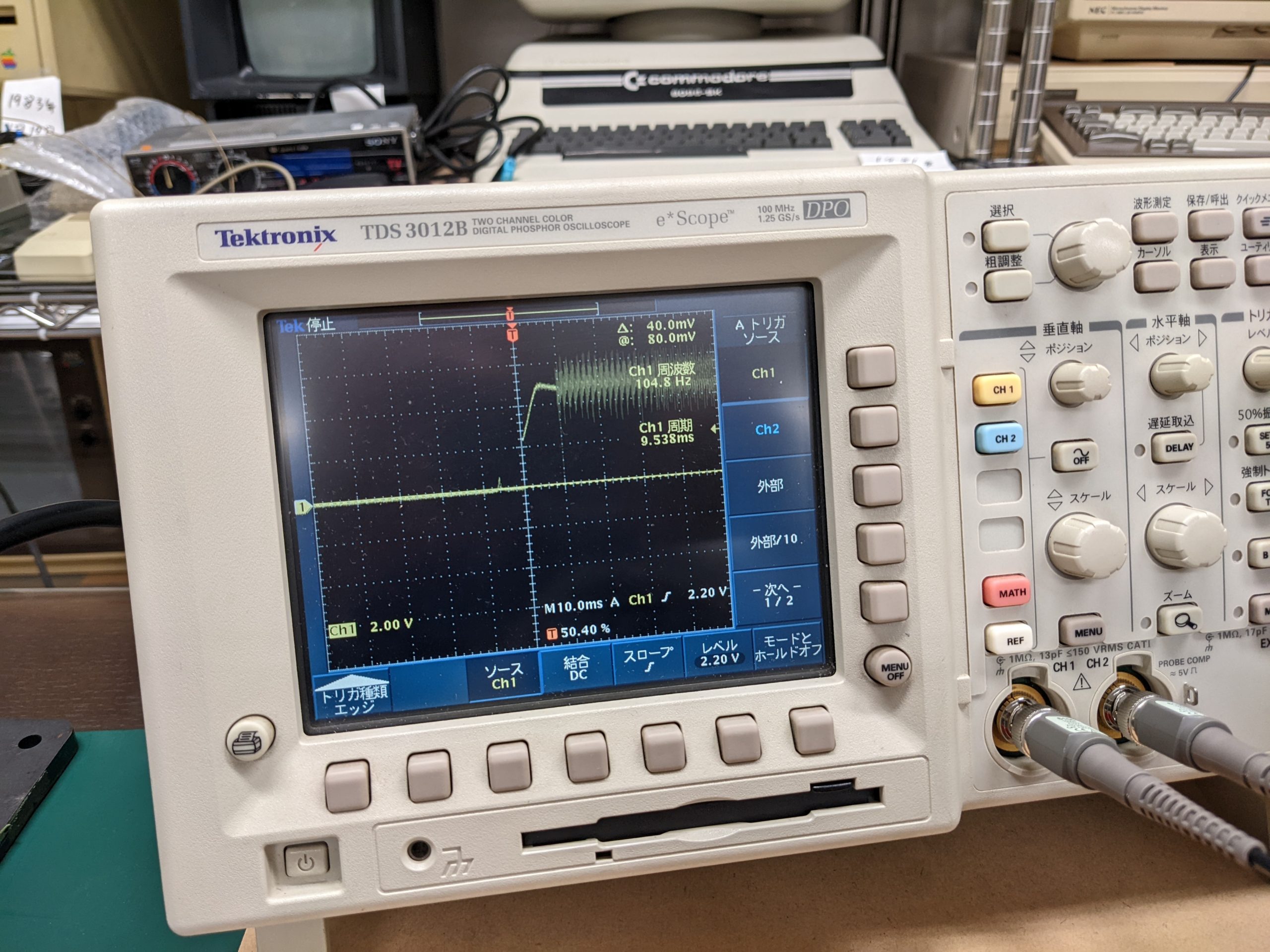
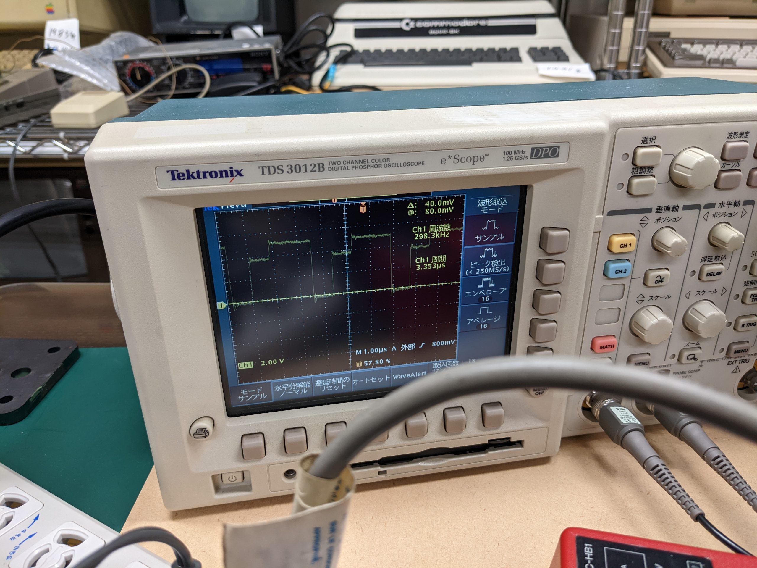
- I’d recommend probing using an oscilloscope first
- Paste program listing into the Arduino IDE
- Connect Arduino via USB to host computer
- Press Upload button
- Disconnect Arduino from host computer
- Wire up Arduino to IC test clip (D2 == pin 1, D3 == pin 2, …, D12 == pin 11, A0 == pin 12, …, A4 == pin 16)
- Make sure device to be tested is powered off and attach test clip to chip inside device
- Connect Arduino to host computer and open Serial Monitor in the Arduino IDE (or e.g. minicom)
- Turn on device to be tested and make sure device powers on normally (or if it never powered on normally in the first place, make sure that it isn’t worse now)
- In your serial terminal application, select what kind of chip to test and start monitoring (currently supported chips are: 74×00, 74×02, 74×04, 74×08, 74×32, 74×125, 74×138, 74×157)
- If you get errors where you didn’t expect any, check your connections (check if the test clip is seated correctly, especially)
- Turn off device under test
- Disconnect Arduino from host computer (Warning: It’s possible to power the Arduino through the GPIO pins. Doing this may damage the Arduino, so always make sure that the device under test is powered off before the Arduino is disconnected from USB.)
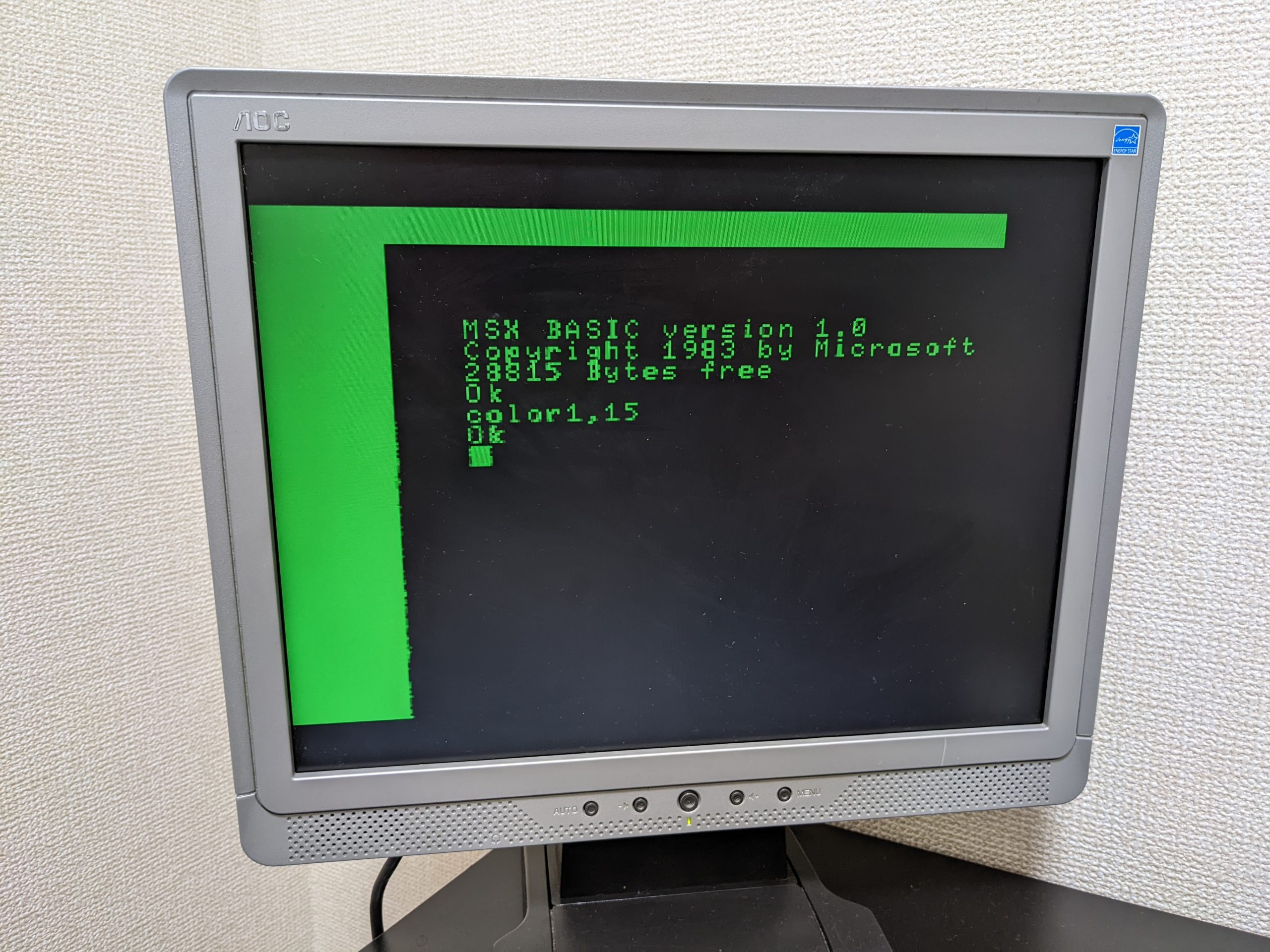
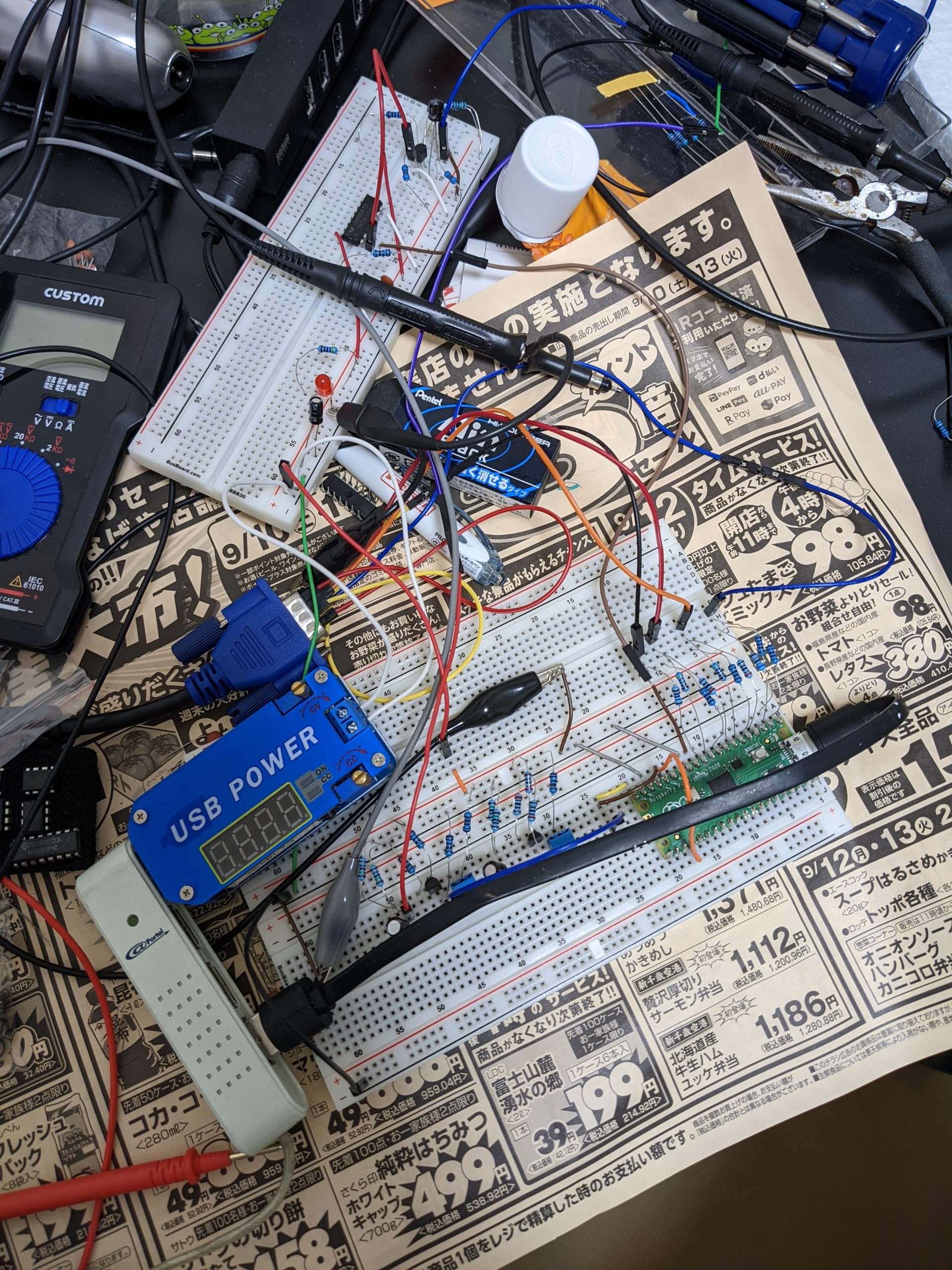
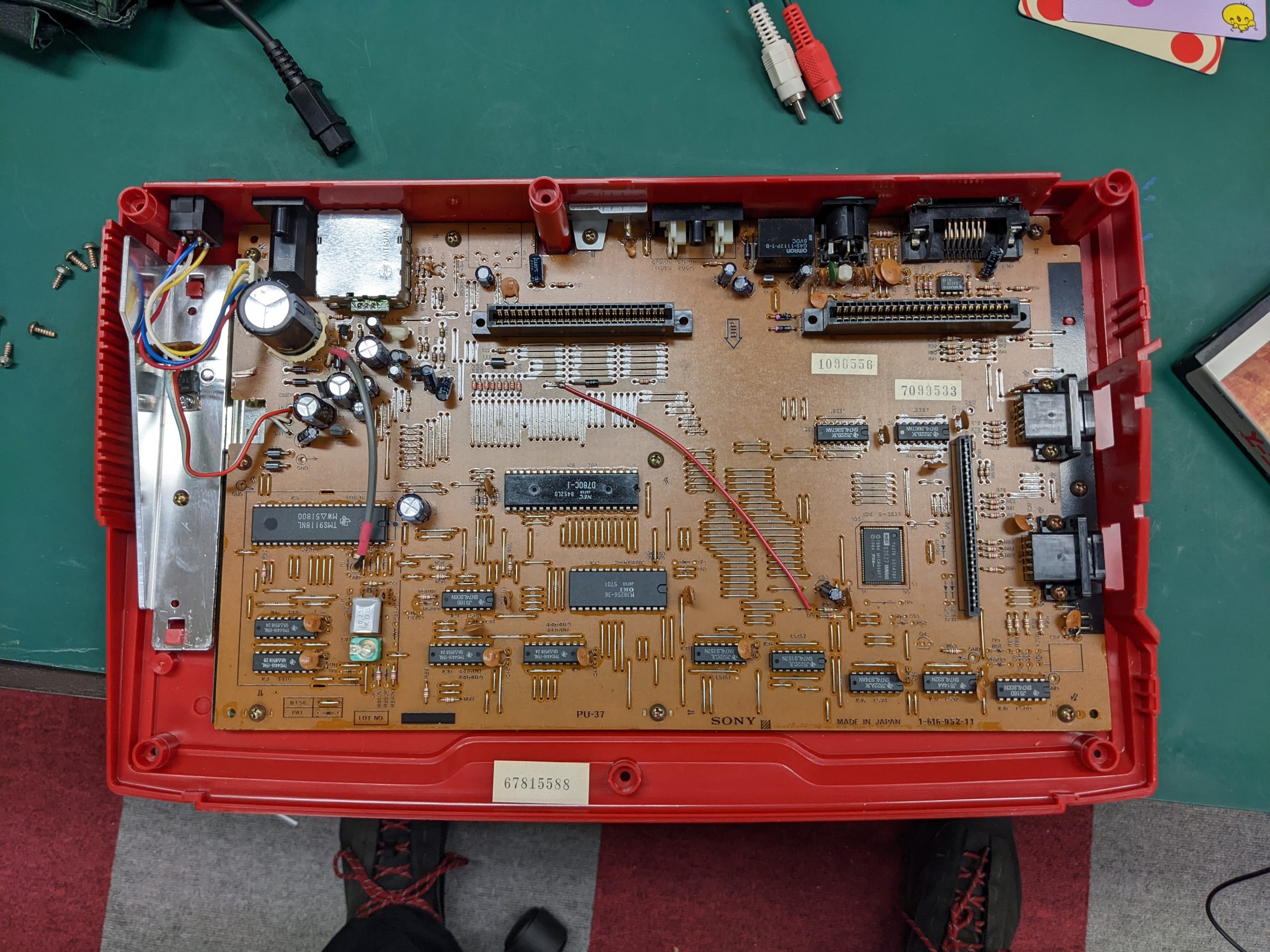
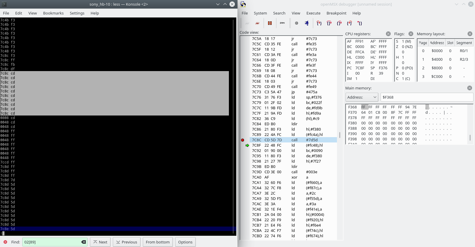
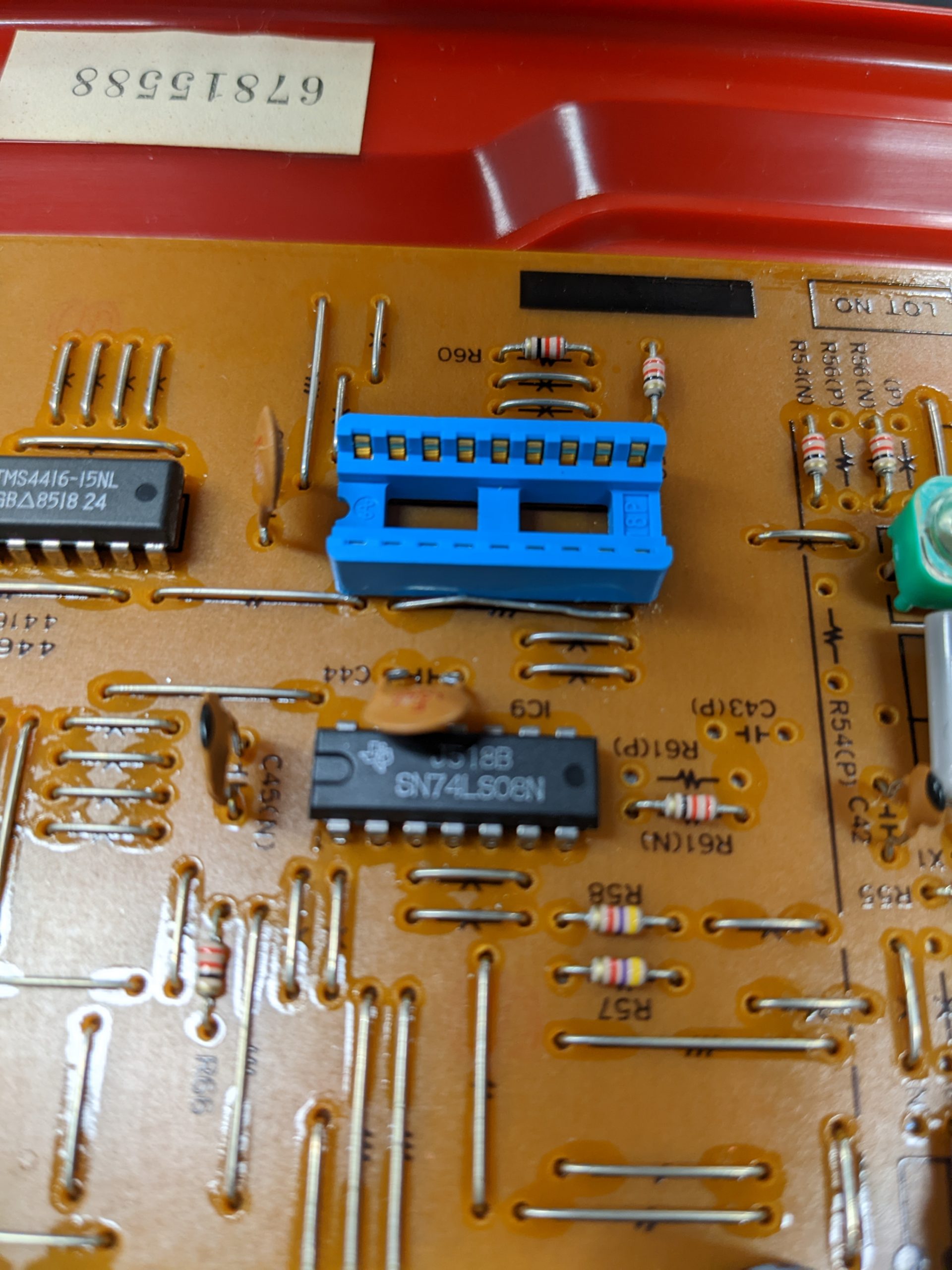
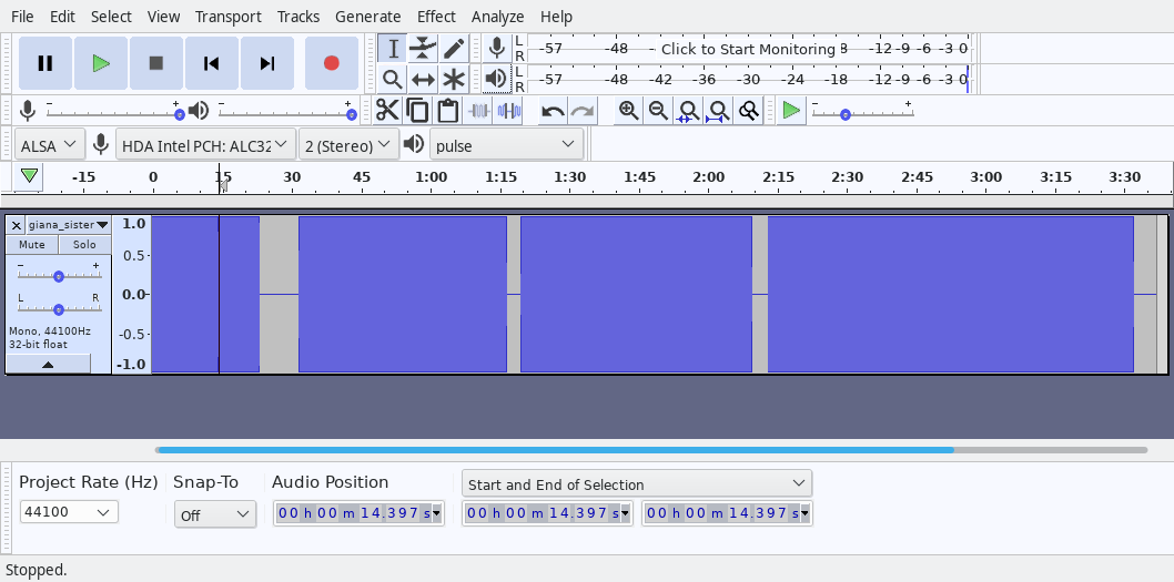
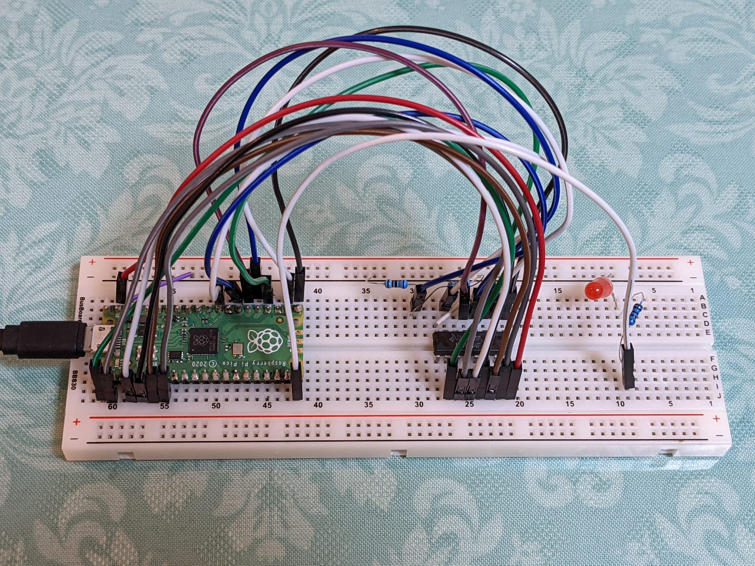
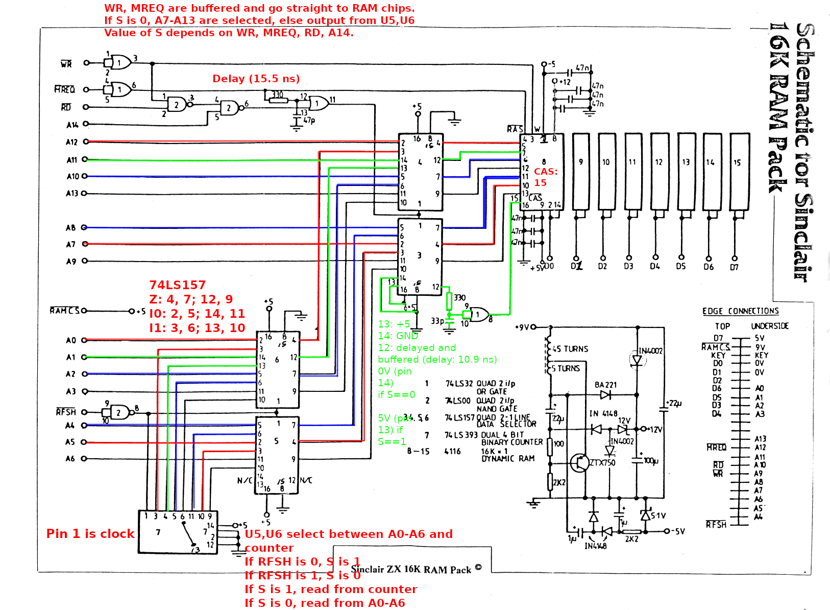
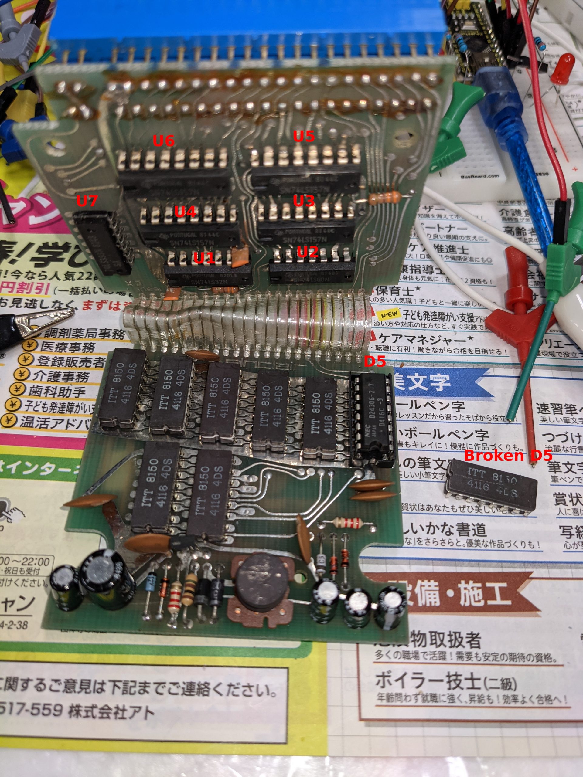
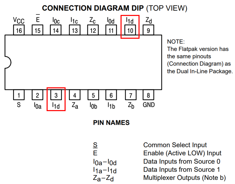
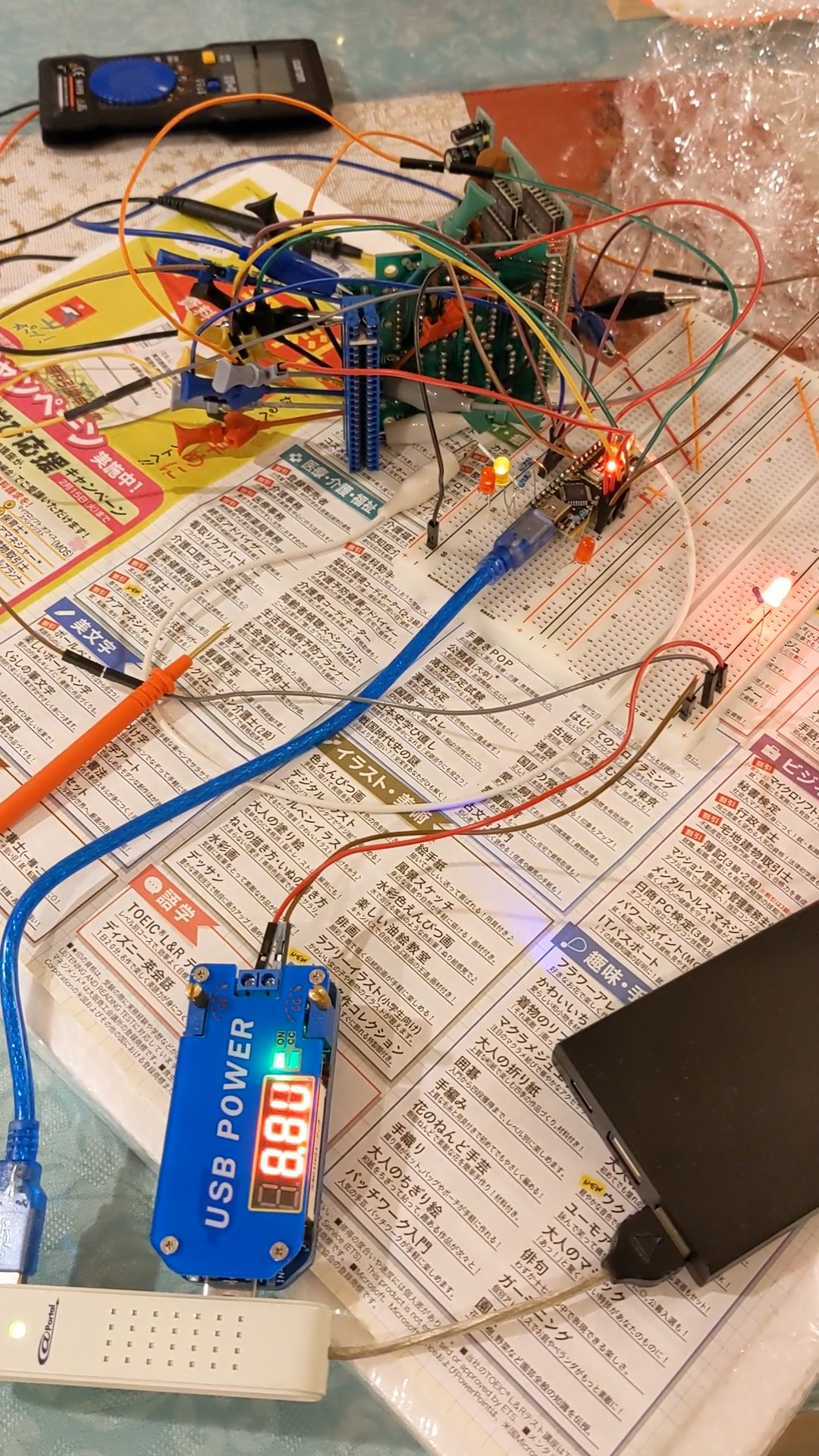
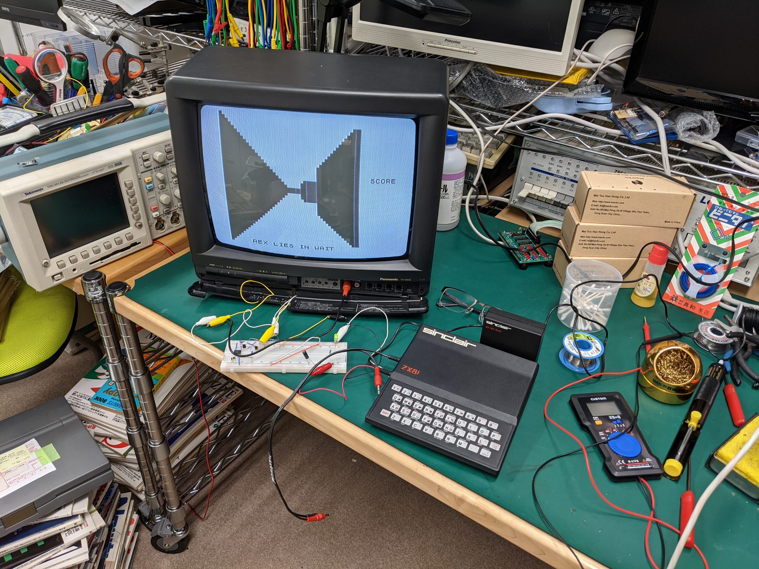
Here are some pics and screenshots:
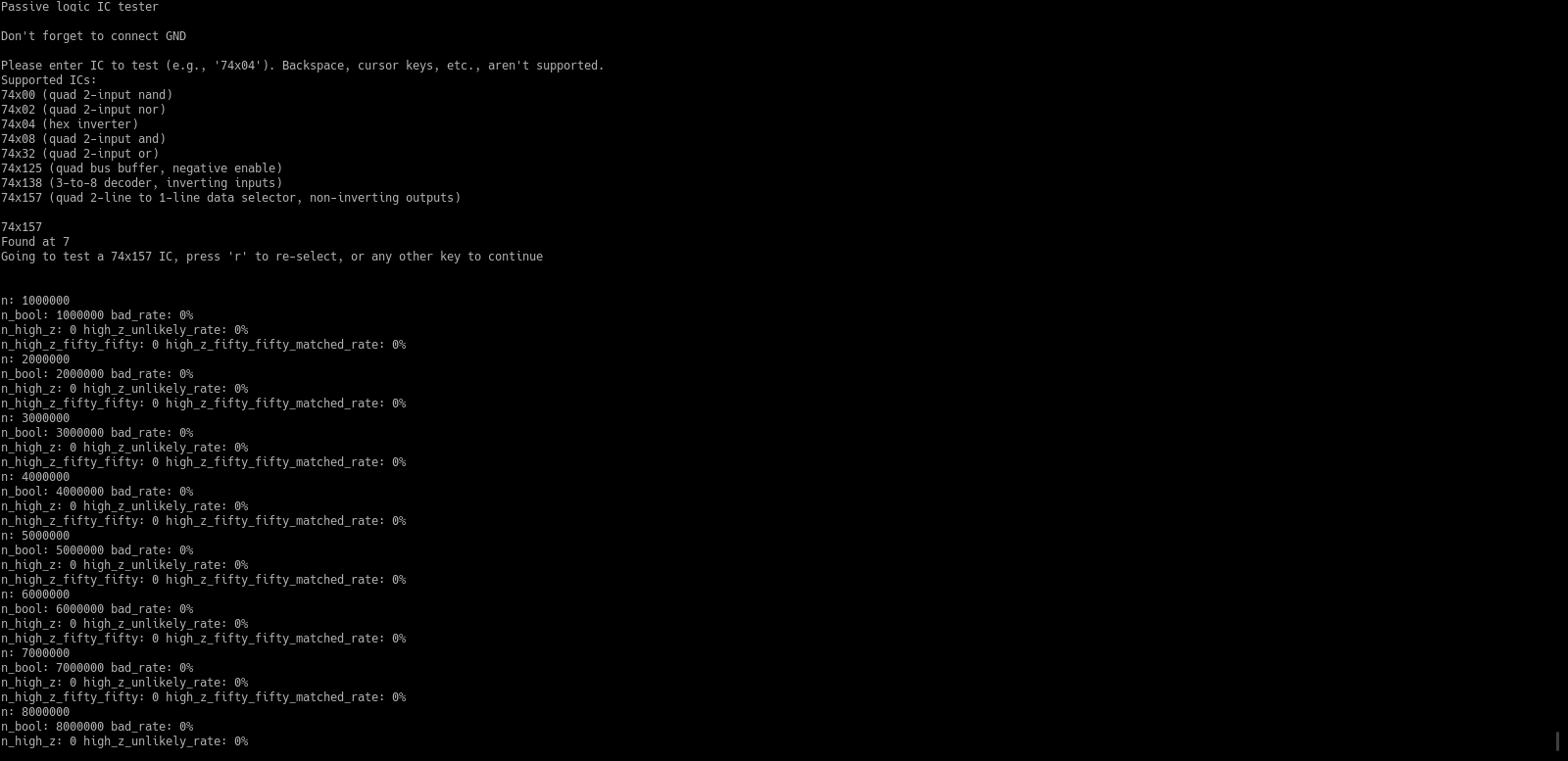

Note, this is very beta-quality, or even “POC-quality”, software. In particular, I implemented some chip tests without ever testing them (because my device doesn’t have those chips). And the ones I did test, I tested only once or so. In even more particular, I don’t think I ever had a chance to test any chips with high impedance states. So it’s entirely possible that the code related to that is 100% bollocks. Use this code at your own risk and only if you mostly know what you are doing.
Another note: my test clip is a 14-pin clip, which means that pins 8 and 9 are read using GPIO pins that aren’t adjacent to the ones reading pins 7 or 10. Look for “USING_A_14_PIN_TEST_CLIP” to see how this is done.
#include <string.h>
#include <unistd.h>

#define ARRAY_SIZE(array) (sizeof(array)/sizeof(array[0]))

#define ALL_REGULAR_GPIO_PINS 0b00011100011111111111111111111111
#define CHIP_NAME_MAX_LENGTH 6

#define LOGIC_BUFFER_LEN 128
#define PRINTF_BUFFER_LEN 96

#define MAX_BAD_RATE 1 // percent
#define MAX_HIGH_Z_UNLIKELY_RATE 10 // percent

#define REPORT_STATISTICS_EVERY_N_SAMPLES 100000

#define WAIT_UNTIL_CONSISTENT 1

// set below define when testing 16-pin chips using a 14-pin test clip and two extra wires for pin 8 and pin 9, as such:
// gpio 0 will be connected to pin 1
// gpio 1 will be connected to pin 2
// ...
// gpio 6 will be connected to pin 7
// gpio 7 will be connected to pin 10(!)
// gpio 8 will be connected to pin 11
// ...
// gpio 13 will be connected to pin 16
// gpio 14 will be connected through extra wire to pin 8
// gpio 15 will be connected through extra wire to pin 9
#define USING_A_14_PIN_TEST_CLIP 1

#define printf(...) sprintf(printf_buffer, __VA_ARGS__); Serial.println(printf_buffer); Serial.flush();
#define printf_verbose(...) { if (verbose == true) { printf(__VA_ARGS__); } }

char printf_buffer[PRINTF_BUFFER_LEN];
uint16_t logic_buffer[LOGIC_BUFFER_LEN];
bool verbose = false;

// organically grown enum
enum test_result_enum {
    BAD = 0,
    GOOD = 1,
    HIGH_Z_UNLIKELY = 2,
    HIGH_Z_LIKELY = 3,
    HIGH_Z_INT2 = 4
};
struct test_result {
    enum test_result_enum test_result_enum;
    unsigned int int1;
    unsigned int int2;
};

// some definitions for convenience
const struct test_result TEST_RESULT_GOOD = {
    .test_result_enum = GOOD,
    .int1 = 0,
    .int2 = 0
};
const struct test_result TEST_RESULT_BAD = {
    .test_result_enum = BAD,
    .int1 = 0,
    .int2 = 0
};
const struct test_result TEST_RESULT_HIGH_Z_UNLIKELY = {
    .test_result_enum = HIGH_Z_UNLIKELY,
    .int1 = 0,
    .int2 = 0
};
const struct test_result TEST_RESULT_HIGH_Z_LIKELY = {
    .test_result_enum = HIGH_Z_LIKELY,
    .int1 = 0,
    .int2 = 0
};
const struct test_result TEST_RESULT_HIGH_Z_INT2 = {
    .test_result_enum = HIGH_Z_INT2,
    .int1 = 0,
    .int2 = 0
};

struct overlay_struct_14 {
    bool pin1 : 1;
    bool pin2 : 1;
    bool pin3 : 1;
    bool pin4 : 1;
    bool pin5 : 1;
    bool pin6 : 1;
    bool pin7 : 1;
    bool pin8 : 1;
    bool pin9 : 1;
    bool pin10 : 1;
    bool pin11 : 1;
    bool pin12 : 1;
    bool pin13 : 1;
    bool pin14 : 1;
} __attribute__((packed));

#ifndef USING_A_14_PIN_TEST_CLIP
struct overlay_struct_16 {
    bool pin1 : 1;
    bool pin2 : 1;
    bool pin3 : 1;
    bool pin4 : 1;
    bool pin5 : 1;
    bool pin6 : 1;
    bool pin7 : 1;
    bool pin8 : 1;
    bool pin9 : 1;
    bool pin10 : 1;
    bool pin11 : 1;
    bool pin12 : 1;
    bool pin13 : 1;
    bool pin14 : 1;
    bool pin15 : 1;
    bool pin16 : 1;
} __attribute__((packed));
#else // renumber some pins
struct overlay_struct_16 {
    bool pin1 : 1;
    bool pin2 : 1;
    bool pin3 : 1;
    bool pin4 : 1;
    bool pin5 : 1;
    bool pin6 : 1;
    bool pin7 : 1;
    bool pin10 : 1;
    bool pin11 : 1;
    bool pin12 : 1;
    bool pin13 : 1;
    bool pin14 : 1;
    bool pin15 : 1;
    bool pin16 : 1;
    bool pin8 : 1;
    bool pin9 : 1;
} __attribute__((packed));
#endif

static_assert(sizeof(struct overlay_struct_14) == 2, "overlay_struct_14 has to be exactly 2 bytes, otherwise it isn't a valid overlay struct for 14 pins!");
static_assert(sizeof(struct overlay_struct_16) == 2, "overlay_struct_16 has to be exactly 2 bytes, otherwise it isn't a valid overlay struct for 16 pins!");

union uint_on_overlay_struct {
    uint16_t uint;
    struct overlay_struct_14 overlay_struct_14;
    struct overlay_struct_16 overlay_struct_16;
};

enum chip_type {
    STATELESS_LOGIC = 0,
    STATEFUL_LOGIC = 1
};

const char *chip_names[] = {
    "74x00",
    "74x02",
    "74x04",
    "74x08",
    "74x32",
    "74x125",
    "74x138",
    "74x157"
};
const enum chip_type chip_types[] = {
    STATELESS_LOGIC,
    STATELESS_LOGIC,
    STATELESS_LOGIC,
    STATELESS_LOGIC,
    STATELESS_LOGIC,
    STATELESS_LOGIC,
    STATELESS_LOGIC,
    STATELESS_LOGIC
};

void no_power_wait(union uint_on_overlay_struct original_input) {
    printf("Chip isn't powered, inserting 1000 ms sleep\n");
    printf_verbose("Current state: %04x\n", original_input.uint);
    delay(1000);
}

void error_blink(void) {
    while (true) {
        digitalWrite(13, false);
        delay(50);
        digitalWrite(13, true);
        delay(50);
    }
}

struct test_result validate_74x00(union uint_on_overlay_struct original_input) {
    struct overlay_struct_14 input = original_input.overlay_struct_14;
    if (input.pin14) { // VCC
        if (((input.pin1 & input.pin2) != input.pin3) &&
            ((input.pin4 & input.pin5) != input.pin6) &&
            ((input.pin13 & input.pin12) != input.pin11) &&
            ((input.pin10 & input.pin9) != input.pin8)) {
            return TEST_RESULT_GOOD;
        } else {
            return TEST_RESULT_BAD;
        }
    } else {
        no_power_wait(original_input);
    }
    return TEST_RESULT_GOOD;
}
struct test_result validate_74x02(union uint_on_overlay_struct original_input) {
    struct overlay_struct_14 input = original_input.overlay_struct_14;
    if (input.pin14) { // VCC
        if (((input.pin2 | input.pin3) != input.pin1) &&
            ((input.pin5 | input.pin6) != input.pin4) &&
            ((input.pin12 | input.pin11) != input.pin13) &&
            ((input.pin9 | input.pin8) != input.pin10)) {
            return TEST_RESULT_GOOD;
        } else {
            return TEST_RESULT_BAD;
        }
    } else {
        no_power_wait(original_input);
    }
    return TEST_RESULT_GOOD;
}
struct test_result validate_74x04(union uint_on_overlay_struct original_input) {
    struct overlay_struct_14 input = original_input.overlay_struct_14;
    if (input.pin14) { // VCC
        if ((input.pin1 != input.pin2) &&
            (input.pin3 != input.pin4) &&
            (input.pin5 != input.pin6) &&
            (input.pin13 != input.pin12) &&
            (input.pin11 != input.pin10) &&
            (input.pin9 != input.pin8)) {
            return TEST_RESULT_GOOD;
        } else {
            return TEST_RESULT_BAD;
        }
    } else {
        no_power_wait(original_input);
    }
    return TEST_RESULT_GOOD;
}
struct test_result validate_74x08(union uint_on_overlay_struct original_input) {
    struct overlay_struct_14 input = original_input.overlay_struct_14;
    if (input.pin14) { // VCC
        if (((input.pin1 & input.pin2) == input.pin3) &&
            ((input.pin4 & input.pin5) == input.pin6) &&
            ((input.pin13 & input.pin12) == input.pin11) &&
            ((input.pin10 & input.pin9) == input.pin8)) {
            return TEST_RESULT_GOOD;
        } else {
            return TEST_RESULT_BAD;
        }
    } else {
        no_power_wait(original_input);
    }
    return TEST_RESULT_GOOD;
}
struct test_result validate_74x32(union uint_on_overlay_struct original_input) {
    struct overlay_struct_14 input = original_input.overlay_struct_14;
    if (input.pin14) { // VCC
        if (((input.pin1 | input.pin2) == input.pin3) &&
            ((input.pin4 | input.pin5) == input.pin6) &&
            ((input.pin13 | input.pin12) == input.pin11) &&
            ((input.pin10 | input.pin9) == input.pin8)) {
            return TEST_RESULT_GOOD;
        } else {
            return TEST_RESULT_BAD;
        }
    } else {
        no_power_wait(original_input);
    }
    return TEST_RESULT_GOOD;
}

struct test_result validate_74x125(union uint_on_overlay_struct original_input) {
    struct overlay_struct_14 input = original_input.overlay_struct_14;
    unsigned int unlikely = 0;
    struct test_result res = TEST_RESULT_HIGH_Z_INT2;
    if (input.pin14) { // VCC
        if (!input.pin1) {
            if (input.pin3 != input.pin2) return TEST_RESULT_BAD;
        }
        if (!input.pin4) {
            if (input.pin6 != input.pin5) return TEST_RESULT_BAD;
        }
        if (!input.pin13) {
            if (input.pin12 != input.pin11) return TEST_RESULT_BAD;
        }
        if (!input.pin10) {
            if (input.pin9 != input.pin8) return TEST_RESULT_BAD;
        }

        if (input.pin1) {
            if (input.pin3 != input.pin2) unlikely++;
        }
        if (input.pin4) {
            if (input.pin6 != input.pin5) unlikely++;
        }
        if (input.pin13) {
            if (input.pin12 != input.pin11) unlikely++;
        }
        if (input.pin10) {
            if (input.pin9 != input.pin8) unlikely++;
        }
        res = TEST_RESULT_HIGH_Z_INT2;
        res.int1 = unlikely;
        res.int2 = 4-unlikely; // 4 is the number of outputs on this chip
        return res;
    } else {
        no_power_wait(original_input);
    }
    return TEST_RESULT_GOOD;
}

struct test_result validate_74x138(union uint_on_overlay_struct original_input) {
    struct overlay_struct_16 input = original_input.overlay_struct_16;
    uint8_t select = input.pin1 | (input.pin2 << 1) | (input.pin3 << 2);
    uint8_t output = input.pin15 | (input.pin14 << 1) | (input.pin13 << 2) | (input.pin12 << 3) | (input.pin11 << 4) | (input.pin10 << 5) | (input.pin9 << 6) | (input.pin7 << 7);
    if (input.pin16) { // VCC
        if (input.pin6 & !input.pin4 & !input.pin5) { // chip enabled
            // select == 0 then 1, select == 1 then 2, select == 2 then 4, select == 3 then 8, ...
            if (output == ~(1<<select)) {
                return TEST_RESULT_GOOD;
            } else {
                return TEST_RESULT_BAD;
            }
        } else { // chip not enabled
            if (output == 0xff) {
                return TEST_RESULT_GOOD;
            } else {
                return TEST_RESULT_BAD;
            }
        }
    } else {
        no_power_wait(original_input);
    }
    return TEST_RESULT_GOOD;
}
struct test_result validate_74x157(union uint_on_overlay_struct original_input) {
    struct overlay_struct_16 input = original_input.overlay_struct_16;
    uint8_t select = input.pin1;

    if (input.pin16) { // VCC
        if (!input.pin15) { // chip enabled
            if (!select) {
                if ((input.pin4 == input.pin2) &&
                    (input.pin7 == input.pin5) &&
                    (input.pin12 == input.pin14) &&
                    (input.pin9 == input.pin11)) {
                    return TEST_RESULT_GOOD;
                } else {
                    return TEST_RESULT_BAD;
                }
            } else {
                if ((input.pin4 == input.pin3) &&
                    (input.pin7 == input.pin6) &&
                    (input.pin12 == input.pin13) &&
                    (input.pin9 == input.pin10)) {
                    return TEST_RESULT_GOOD;
                } else {
                    return TEST_RESULT_BAD;
                }
            }
        } else { // chip not enabled
            // high-impedance
            // we can check for high-impedance heuristically
            // check for activity that would not be possible with an enabled (and working) chip
            // partially mirrors above code
            if (!select) {
                if ((input.pin4 == input.pin2) &&
                    (input.pin7 == input.pin5) &&
                    (input.pin12 == input.pin14) &&
                    (input.pin9 == input.pin11)) {
                    return TEST_RESULT_HIGH_Z_UNLIKELY;
                } else {
                    return TEST_RESULT_HIGH_Z_LIKELY;
                }
            } else {
                if ((input.pin4 == input.pin3) &&
                    (input.pin7 == input.pin6) &&
                    (input.pin12 == input.pin13) &&
                    (input.pin9 == input.pin10)) {
                    return TEST_RESULT_HIGH_Z_UNLIKELY;
                } else {
                    return TEST_RESULT_HIGH_Z_LIKELY;
                }
            }
        }
    } else {
        no_power_wait(original_input);
    }
    return TEST_RESULT_GOOD;
}

struct test_result (*chip_check_funcs[])(union uint_on_overlay_struct) = {
    validate_74x00,
    validate_74x02,
    validate_74x04,
    validate_74x08,
    validate_74x32,
    validate_74x125,
    validate_74x138,
    validate_74x157
};

void setup() {
    unsigned int i = 0, j = 0;
    size_t chars_read = 0;
    char input_buffer[CHIP_NAME_MAX_LENGTH+1] = { 0 };
    bool found = false;
    union uint_on_overlay_struct gpio_input = { 0 };
    register uint8_t gpio_input_b = 0, gpio_input_c = 0, gpio_input_d = 0; // intended effect of 'register': gpio_input_b = PORTB is translated into a single instruction (e.g., in r24, 0x05). seems to work as intended.
    register uint8_t gpio_input_b2 = 0, gpio_input_c2 = 0, gpio_input_d2 = 0;
    struct test_result test_result = { 0 };
    unsigned long int bad = 0, good = 0, high_z_likely = 0, high_z_unlikely = 0, high_z_fifty_fifty_matched = 0, high_z_fifty_fifty_unmatched = 0;
    unsigned long int bad_rate = 0, high_z_unlikely_rate = 0, high_z_fifty_fifty_matched_rate = 0;
    unsigned long int n_bool = 0, n_high_z = 0, n_high_z_fifty_fifty = 0, n = 0;

    Serial.begin(115200);

    pinMode(2, INPUT);
    pinMode(3, INPUT);
    pinMode(4, INPUT);
    pinMode(5, INPUT);
    pinMode(6, INPUT);
    pinMode(7, INPUT);
    pinMode(8, INPUT);
    pinMode(9, INPUT);

    pinMode(10, INPUT);
    pinMode(11, INPUT);
    pinMode(12, INPUT);
    pinMode(A0, INPUT);
    pinMode(A1, INPUT);
    pinMode(A2, INPUT);
    pinMode(A3, INPUT);
    pinMode(A4, INPUT);

    pinMode(13, OUTPUT); // onboard LED

    // wait a little bit
    for (i = 0; i < 5; i++) {
        digitalWrite(13, HIGH);
        delay(500);
        digitalWrite(13, LOW);
        delay(500);
    }
    digitalWrite(13, HIGH);
    printf("Passive logic IC tester\n");
    printf("Make sure that voltages on pins to be tested are between 0 and 5V\n");
    printf("Don't forget to connect GND\n\n");

    Serial.flush(); // flush serial output
    while (Serial.available()) {
        Serial.read(); // flush serial input
    }

    printf("Verbose mode? (y/N)\n");
    while (!Serial.available());
    switch (Serial.read()) {
        case 'y':
        case 'Y':
            verbose = true;
            break;
        default:
            verbose = false;
    }

    while (true) {
        printf("Please enter IC to test (e.g., '74x04'). Backspace, cursor keys, etc., aren't supported.\n");
        printf("Supported ICs:\n");
        printf("74x00 (quad 2-input nand)\n");
        printf("74x02 (quad 2-input nor)\n");
        printf("74x04 (hex inverter)\n");
        printf("74x08 (quad 2-input and)\n");
        printf("74x32 (quad 2-input or)\n");
        printf("74x125 (quad bus buffer, negative enable)\n");
        printf("74x138 (3-to-8 decoder, inverting inputs)\n");
        printf("74x157 (quad 2-line to 1-line data selector, non-inverting outputs)\n");

        Serial.flush(); // flush serial output
        while (Serial.available()) {
            Serial.read(); // flush serial input
        }
        for (chars_read = 0; chars_read < CHIP_NAME_MAX_LENGTH; chars_read++) {
            while (!Serial.available());
            input_buffer[chars_read] = Serial.read();
        }
        printf("\n");
        for (i = 0; i < ARRAY_SIZE(chip_names); i++) {
            if (memcmp(input_buffer, chip_names[i], min(chars_read, strlen(chip_names[i]))) == 0) {
                printf("Found at %d\n", i);
                delay(1000);
                printf("Going to test a %s IC, press 'r' to re-select, or any other key to continue\n", chip_names[i]);
                while (!Serial.available());
                if (Serial.read() != 'r') {
                    found = true;
                }
                printf("\n");
                break; // break inner for loop
            }
        }
        if (found) {
            break; // break while loop
        }
        if (i == ARRAY_SIZE(chip_names)) {
            printf("Unknown chip: \"%s\"\n", input_buffer);
        }
    }

    if (chip_types[i] == STATELESS_LOGIC) {
        while (true) {
            while (true) {
                gpio_input_d = PIND;
                gpio_input_b = PINB;
                gpio_input_c = PINC;
#ifdef WAIT_UNTIL_CONSISTENT
                gpio_input_d2 = PIND;
                gpio_input_b2 = PINB;
                gpio_input_c2 = PINC;
                if ((gpio_input_d == gpio_input_d2) &&
                    (gpio_input_b == gpio_input_b2) &&
                    (gpio_input_c == gpio_input_c2)) {
                    break;
                }
#else
                break;
#endif
            }
            gpio_input.uint = ((gpio_input_d & 0xfc) >> 2) | ((uint16_t)(gpio_input_b & 0x1f) << 6) | ((uint16_t)(gpio_input_c & 0x1f) << 11);
            test_result = chip_check_funcs[i](gpio_input);
            switch (test_result.test_result_enum) {
                case BAD:
                    bad++;
                    printf_verbose("Bad state: %04x\n", gpio_input.uint);
                    break;
                case GOOD:
                    good++;
                    break;
                case HIGH_Z_UNLIKELY:
                    high_z_unlikely++;
                    break;
                case HIGH_Z_LIKELY:
                    high_z_likely++;
                    break;
                case HIGH_Z_INT2:
                    high_z_fifty_fifty_matched += test_result.int1;
                    high_z_fifty_fifty_unmatched += test_result.int2;
                    break;
            }
            n_bool = good + bad;
            n_high_z = high_z_likely + high_z_unlikely;
            n_high_z_fifty_fifty = high_z_fifty_fifty_matched + high_z_fifty_fifty_unmatched;
            n = n_bool + n_high_z + n_high_z_fifty_fifty;
            if ((n % REPORT_STATISTICS_EVERY_N_SAMPLES) == 0) {
                bad_rate = (100*bad)/n_bool; // fixed point, 0.01 -> 1
                high_z_unlikely_rate = (100*high_z_unlikely)/n_high_z;
                high_z_fifty_fifty_matched_rate = (100*high_z_fifty_fifty_matched)/n_high_z_fifty_fifty;
                printf("n: %lu\n", n);
                printf("n_bool: %lu bad_rate: %lu%%\n", n_bool, bad_rate);
                printf("n_high_z: %lu high_z_unlikely_rate: %lu%%\n", n_high_z, high_z_unlikely_rate);
                printf("n_high_z_fifty_fifty: %lu high_z_fifty_fifty_matched_rate: %lu%%\n", n_high_z_fifty_fifty, high_z_fifty_fifty_matched_rate);

// below lines are commented out because i didn't need this functionality after all
//                if (bad_rate > MAX_BAD_RATE) { // some bad results are allowed because we might be sampling right before the chip had a chance to respond to inputs
//                    error_blink();
//                }
//                if (high_z_unlikely_rate > MAX_HIGH_Z_UNLIKELY_RATE) { // some bad results are allowed because we may sometimes sample right before the chip had a chance to respond to inputs
//                    error_blink();
//                }
            }
        }
    } else {
        for (j = 0; j < LOGIC_BUFFER_LEN; j++) {
            gpio_input_d = PORTD;
            gpio_input_b = PORTB;
            gpio_input_c = PORTC;
            logic_buffer[j] = ((gpio_input_d & 0xfc) >> 2) | ((uint32_t)(gpio_input_b & 0x1f) << 6) | ((uint32_t)(gpio_input_c & 0x1f) << 11);
        }
        for (j = 0; j < LOGIC_BUFFER_LEN; j++) {
            gpio_input.uint = logic_buffer[j];
            test_result = chip_check_funcs[i](gpio_input);
            switch (test_result.test_result_enum) {
                case BAD:
                    bad++;
                    printf_verbose("Bad state: %04x\n", logic_buffer[j]&0xffff);
                    break;
                case GOOD:
                    good++;
                    printf_verbose("Good state: %04x\n", logic_buffer[j]&0xffff);
                    break;
                case HIGH_Z_UNLIKELY:
                    high_z_unlikely++;
                    break;
                case HIGH_Z_LIKELY:
                    high_z_likely++;
                    break;
                case HIGH_Z_INT2:
                    high_z_fifty_fifty_matched += test_result.int1;
                    high_z_fifty_fifty_unmatched += test_result.int2;
                    break;
            }
        }

        n_bool = good + bad;
        n_high_z = high_z_likely + high_z_unlikely;
        n_high_z_fifty_fifty = high_z_fifty_fifty_matched + high_z_fifty_fifty_unmatched;
        n = n_bool + n_high_z + n_high_z_fifty_fifty;

        bad_rate = (100*bad)/n_bool; // fixed point, 0.01 -> 1
        high_z_unlikely_rate = (100*high_z_unlikely)/n_high_z;
        high_z_fifty_fifty_matched_rate = (100*high_z_fifty_fifty_matched)/n_high_z_fifty_fifty;
        printf("n: %lu\n", n);
        printf("n_bool: %lu bad_rate: %lu%%\n", n_bool, bad_rate);
        printf("n_high_z: %lu high_z_unlikely_rate: %lu%%\n", n_high_z, high_z_unlikely_rate);
        printf("n_high_z_fifty_fifty: %lu high_z_fifty_fifty_matched_rate: %lu%%\n", n_high_z_fifty_fifty, high_z_fifty_fifty_matched_rate);
    }
}

void loop() {
}


