I recently stumbled upon some source code I wrote when I was 18! I was very much into graphical effects back then, and all of that code targeted SVGAlib, which isn’t really a thing anymore. So I teamed up with ChatGPT to write a thin translation layer to SDL, and I believe I got all of my code to work! Mind you, I didn’t use any advanced features. Just setting modes, setting pixels, and setting the palette.
I (and/or ChatGPT) didn’t implement anything beyond what I needed. Therefore, only the following modes are supported:
G800x600x256 (palette-based) G800x600x64K (16-bit color depth RGB) G1024x768x16M (24-bit color depth RGB)
And that’s it, really. Also, the palette mode is implemented in software.
Does it just work without modifying the source at all? No, not quite. In SVGAlib, all graphics calls are effective immediately, and you would call e.g. sleep() or usleep() to slow down animations. In SDL2, you tell the library that it’s okay to render a frame now. Also, if you modify the palette when you already had something onscreen, and you want the existing pixels to reflect the changes to the palette (usually the case), you need to call a function that redraws the whole screen.
What this means: 1) add a call to vga_waitretrace() before every sleep or usleep(), 2) add a call to redraw_after_palette_update() after you’re done modifying the palette. So let’s say if you have a program like this:
#include <vga.h>

int main()
{
  int x, y;
  vga_init();
  vga_setmode(G800x600x256);

  for (y = 0; y <= 599; y++) {
    for (x = 0; x <= 799; x++) {
      vga_setcolor(x ^ y);
      vga_drawpixel(x, y);
    }
  }
  sleep(5);
}
You modify it like this:
#include <vga.h>

int main()
{
  int x, y;
  vga_init();
  vga_setmode(G800x600x256);

  for (y = 0; y <= 599; y++) {
    for (x = 0; x <= 799; x++) {
      vga_setcolor(x ^ y);
      vga_drawpixel(x, y);
    }
  }
  vga_waitretrace();
  sleep(5);
}
And you put the vga.h shim into your current directory and compile like this:
I’ve been developing software for the ESP32 and ESP32S3 “professionally” for about one year now. I still like the Raspberry Pi Pico better, but the ESP32 line of microcontrollers is cool too. And if you need wireless and don’t really care too much about power consumption, the ESP32 (or -S3 or what have you) is a nice thing to have around.
The examples in IDF (the name of the ESP32 SDK) are really great, and you can do a bunch of stuff just by taking an example and changing a couple lines.
I’m a huge fan of the Raspberry Pi Pico’s PIO, and the ESP32 has something that is slightly similar, as-in “programmable IO”. It’s called “RMT”, and in examples/peripherals/rmt, we have a few examples that make use of this bit of silicon. The examples/peripherals/rmt/ir_nec_transceiver example is the one we look at in this article.
Basically, all you have to do is flash this to your dev board and connect an IR receiver module’s output pin to GPIO19 (and its VCC and GND to VCC and GND. Be sure to hook it up to 3.3V, not 5V.) If you want to do what this example is supposed to do (output the same signal back through an infrared LED on GPIO18), feel free. But if you just want to sniff codes, leave the infrared LED disconnected and look at the UART output.
Note that the output of the IR receiver is expected to be inverted compared to the actually sent signal. I think most IR receivers invert the signal, so you’ll most likely be fine.
Build steps
If your dev board isn’t a standard ESP32, but e.g. an ESP32S3, you first have to do:
idf.py set-target esp32s3
Then you do:
idf.py flash monitor
This will build the example, flash it to the dev board, and start a monitor.
Then you’ll see a bunch of output like this:
NEC frame start---
{0:218},{1:0}
---NEC frame end: Unknown NEC frame
But if you press a key on a remote control, you may see something like this:
And there you have the address and the command! Note that by default, extended NEC codes are allowed. (However, the remote control I used here generates a non-extended NEC code, where the second byte in the address (and command) is the first byte but inverted. I.e., 0xFF == ^0x00, 0xCE == ^0x31.)
And that’s all! If you output this using an IR LED (make sure you use a resistor), you will be able to control the device in question using your microcontroller. Note that you will probably have to move the LED rather close to the device you’re trying to control (depending on your resistor value). Note that you shouldn’t really exceed 30 mA per GPIO. I understand that most IR LEDs are good up to 100 mA, but the ESP32’s GPIO pins aren’t. You’ll need to amplify the signal if you want to go higher than 30 mA.
Sniffing IR (NEC) codes on the Raspberry Pi Pico
The Pico has a very similar demo, pico-examples/pio/ir_nec/ir_loopback/ir_loopback.c. If all you want to do is sniffing, it may work a little nicer if you comment out the sending stuff (everything from “// create a 32-bit frame and add it to the transmit FIFO” to “sleep_ms(100);”), as well as the sleep_ms(900) at the bottom. (Otherwise you’ll have to wait a little bit until your IR code shows up.) Also, it won’t do extended NEC codes. You’d have to modify nec_receive.c a little bit.
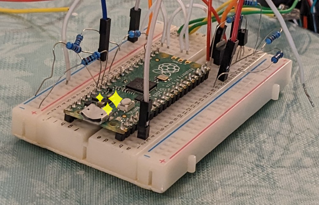
A happy Pico enjoying a round of Mario Kart. (This particular Pico is doing something else, but it’s content watching its brother play.)
Well, it’s time to put 2 and 2 together and get that silly PS3 controller to work on the Switch! (Or on other devices supported by GP2040-CE, which as I understand includes the Xbox and PS4/PS5?) To do this, we just have to realize that the PS3 controller works on Linux. So we just need to figure out how Linux does it. And a quick Google query (though I can’t remember the words I chose) surfaced up an old patch from 2007 introducing PS3 support to the Linux kernel:
Add the USB HID quirk HID_QUIRK_SONY_PS3_CONTROLLER. This sends an HID_REQ_GET_REPORT to the the PS3 controller to put the device into ‘operational mode’.
So, how could we do this in 1) our code that we used for the MSX, and 2) in GP2040-CE?
Modifying Pico-PIO-USB to work with the PS3 controller
Pico-PIO-USB isn’t very over-engineered yet(?!), and we can just modify the enumerate_device function in pio_usb_host.c to check if we’re seeing a PS3 controller, and send the request. Near the bottom of this function, we send the “get_hid_report_descrpitor_request” to the USB device. Immediately after we add our own code, as below:
diff --git a/src/pio_usb_host.c b/src/pio_usb_host.c
index 864d048..0efc567 100644
--- a/src/pio_usb_host.c
+++ b/src/pio_usb_host.c
@@ -1018,6 +1018,21 @@ static int enumerate_device(usb_device_t *device, uint8_t address) {
         printf("\n");
         stdio_flush();

+        // We need to send a special HID request otherwise the contoller won't do anything
+        if ((device->vid == 0x054c) && (device->pid == 0x0268)) {
+          usb_setup_packet_t get_hid_report_ps3_controller_request =
+              GET_HID_REPORT_PS3_CONTROLLER;
+          control_in_protocol(
+              device, (uint8_t *)&get_hid_report_ps3_controller_request,
+              sizeof(get_hid_report_ps3_controller_request), rx_buffer, LINUX__SIXAXIS_REPORT_0xF2_SIZE);
+          printf("\t\tPS3 controller response:");
+          for (int i = 0; i < LINUX__SIXAXIS_REPORT_0xF2_SIZE; i++) {
+            printf("%02x ", device->control_pipe.rx_buffer[i]);
+          }
+          printf("\n");
+          stdio_flush();
+        }
+
       } break;
       default:
         break;
This requires the following definitions to be added in usb_definitions.h. I just used the same names used in Linux (not the ancient 2007 version, but something recent):
So, will the same modifications work in GP2040-CE too? No, while GP2040-CE uses Pico-PIO-USB to get USB host functionality to work at all while the Pico is busy being a USB device, protocol-y stuff is handled by TinyUSB, which by the way is included in the Pico SDK. Looking at pspassthrough.cpp for inspiration, I found that if we just add the following code to our previously modified version of src/addons/keyboard_host.cpp, our PS3 controller wakes up from its daze and starts sending our inputs!
The output is something that can be BLOAD’ed straight to VRAM memory using BLOAD’s S parameter. Didn’t even know that option existed!
This means we can easily convert this to a ROM by adding a loader that pokes everything into VRAM. We just need to get rid of the BSAVE header at the start (or ignore it in the loader), which looks like this according to http://www.faq.msxnet.org/suffix.html#BIN:
So we just cut off 8 bytes at the beginning, e.g. by doing:
tail -c +8 msx_20231111232339933.SC2 > foo.bin
And the loader in assembly (z80asm-flavor) could look like this:
SetVdpWrite: macro high low ; from http://map.grauw.nl/articles/vdp_tut.php
	ld a,low
	out (0x99),a
	ld a,high+0x40
	out (0x99),a
endm

vpoke: macro value
; 	ld a,value ; not needed in this implementation
	out (0x98),a
; 	nop ; nops not needed in this implementation
; 	nop
; 	nop
endm

	org 0x4000
	db "AB" ; magic number
	dw entry_point
	db 00,00,00,00,00,00,00,00,00,00,00,00 ; ignored

entry_point:
	ld a,2
	call 0x005f
	SetVdpWrite 00 00
	ld hl,data
loop:
	ld a,(hl)
	vpoke a
	inc hl
	ld a,h
	cp end>>8
	jr nz,loop
	ld a,l
	cp end&0xff
	jr nz,loop
inf:
	jr inf
data:
	incbin "foo.bin" ; read data from file foo.bin
end:
	ds 0x8000-$ ; fill remainder of 16 KB chunk with 0s
Of course, this approach is quite wasteful; we need almost 16 KB of memory to display any image, even if it’s mostly empty.
Or alternatively: how to get svg2shenzhen to recognize your drill paths as drill holes
(My) rationale: there is an Inkscape extension called svg2shenzhen. This extension creates Gerber and KiCad files that can be used to create printed circuit boards, from standard SVG files. Also, this extension has a funny name. Older, DIY printed circuit boards are just a high-DPI bitmap. Using Inkscape and this extension, you can trace the bitmap and then convert it to Gerber. However, most PCBs (especially old PCBs) need to have holes drilled. The drill locates are just circles in the bitmap, and after tracing, they’re just paths. The svg2shenzhen extension (at the time of this writing) detects circles in a certain layer as locations that need to be drilled, but not paths.
I’m not an Inkscape expert, but AFAIK Inkscape (at the time of this writing) doesn’t have a built-in tool to convert (mostly) circular paths to circles. So I wrote a simple extension that does this! It works fine on Linux. Not so sure about Windows.
Extensions are made of only two files, a file that describes the extension, and the extension code (which is in Python in many cases). These two files just have to be placed into the location shown in Edit -> Preferences -> System -> User extensions, which in my case is ~/.config/inkscape/extensions/.
Here are the two files, you can copy them into a text editor like Kate or gedit or Notepad, what have you, and save them into the above directory. I recommend keeping my file names, path2circle.inx and path2circle.py. Note, some skeleton code in path2circle.py was generated by ChatGPT, though it was quite wrong. That’s where some of the verbose comments and extraneous code came from.
import inkex
from inkex import Circle

class Path2Circle(inkex.EffectExtension):
    def effect(self):
        # Iterate through all the selected objects in the SVG
        for node in self.svg.selection:
            # Check if the object is a path (or any other object type)
            if node.tag.endswith("path"):
                # Get the bounding box of the object
                x, y, width, height = self.get_object_dimensions(node)
                x = x.minimum
                y = y.minimum
                # with open('/path/to/debug/directory/debug_output.txt', 'a') as f:
                    # print(f"Object Dimensions: x={x}, y={y}, width={width}, height={height}", file=f)
                layer = self.svg.get_current_layer()
                diameter = min(width, height)
                layer.add(self.add_circle(x, y, diameter/2))

    def add_circle(self, x, y, radius):
        """Add a circle at the given location"""
        elem = Circle()
        elem.center = (x+radius, y+radius)
        elem.radius = radius
        return elem

    def get_object_dimensions(self, object_node):
        # Get the bounding box of the object
        bbox = object_node.bounding_box()

        # Extract the bounding box coordinates
        x = bbox.x
        y = bbox.y
        width = bbox.width
        height = bbox.height

        return x, y, width, height

if __name__ == '__main__':
    Path2Circle().run()
To use the extension, you probably first need to restart Inkscape. (You do not need to restart Inkscape after changing the extension, however.) Select all the paths you’d like to convert, and then hit Extensions -> Custom -> Path2Circle. Note: the extension doesn’t actually care if the paths even remotely look like circles, so make sure to select the correct paths. You can easily modify the extension to calculate the radius differently, or e.g. replace paths with other objects, such as squares, rectangle, or ellipses. Let me know if you need help doing that.
In a previous post, we did some warmups — playing MSX games using a fake PS3 controller. In this post, we’ll be using GP2040-CE to control a Nintendo Switch. (No analog stick support implemented at the moment, but it wouldn’t be hard.) At the time of writing, most of the code to do this is already there! And I’m sure there will be support for USB-HID controllers in no time, so this post will probably be outdated soon. Update: Analog is implemented too, and the diff below has been updated.
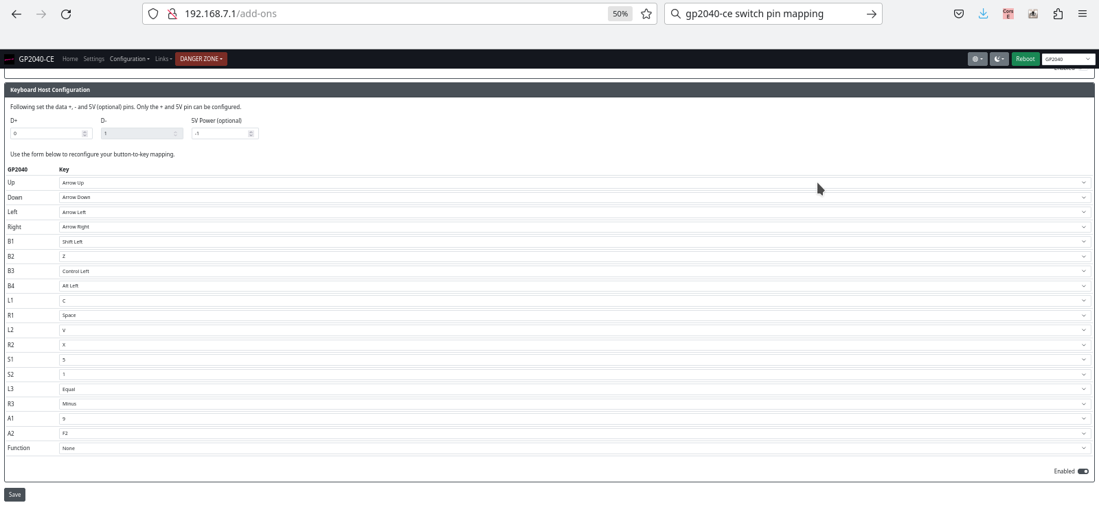
Anyway, you just need to put GP2040-CE on your Pico and get into the web configuration. In add-ons, you enable keyboard support, and then set up the “Keyboard Host Configuration”, which looks like this:
GP2040-CE keyboard mapping and other configuration
Then you can connect a generic USB keyboard to the Raspberry Pi Pico, and connect the Pico to the Nintendo Switch. (For electrical reasons, I do not recommend setting a pin for 5V power here, and just putting the host USB +5 on the VBUS pin of the Pico.)
Things that could come in handy: Breadboard, Raspberry Pi Pico, USB port that can be connected to one of the Pico’s GPIO pins
If everything works and you can control Sonic using your keyboard, great, you can move on to the next step! If it didn’t work, it probably won’t magically get better from here on out, so make sure to check those connections. The green/white wires can be D+/D- or D-/D+!
Now we’ll perform a small modification to the existing code. I’m basing my work on commit 961c49d5b969ee749ae17bd4cbb2f0bad2380e71. Beware, this may or may not work with your controller. I’d recommend taking a look at the above-mentioned previous post where we modify a Pico-PIO-USB example and to check if your controller behaves the same way. I have only two controllers to test with, and I only tested with one! Anyway, here’s the diff:
Good luck. Miraculously, everything worked perfectly for me. The keyboard worked immediately, the above code modification worked immediately without having to do any debugging, and I’ve gotta say, my fake PS3 controller feels quite okay! (Note that you will have to press the PlayStation button after connecting your PS3 controller.)
There is very little code that I wrote myself in this project, but it’s the first time I’m looking at USB-HID on the protocol level and the end result is something mildly useful. So possibly worth a post? (Note: code is at the bottom of this post.)
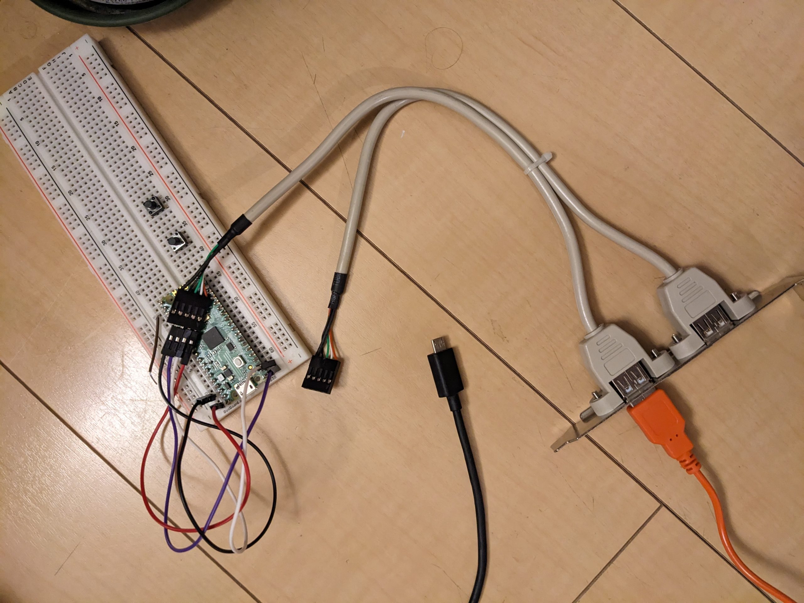
All we’ll be doing here is modify an example from https://github.com/sekigon-gonnoc/Pico-PIO-USB, namely, the capture_hid_report example. You’ll need a good way to connect a USB-A port to your Raspberry Pi Pico. I’m using an old piece of hardware that was meant for use in desktop PCs to add USB ports on the back, internally connected to motherboard headers. (In the demo we’re using, USB D+ and D- are GPIO pins 0 and 1, respectively.)
Once you have your Pico flashed, open a serial terminal, and then connect a USB-HID gamepad. I’m using a fake PS3 controller. It looks very similar to a Sony PS3 controller but bears a “P3” mark instead of the PlayStation logo on the middle button. (I don’t know if it works with a real PS3.) (I’m leaving out the wiring details here, but it’s all exactly as explained in the README.md in the repo.) I get the following messages when I plug in my controller. The “EP 0x81” messages are sent continuously.
You can also use Linux tools such as usbhid-dump to get reports, but for some reason they look quite different from what I get here. Don’t know if the driver is doing something (odd, or not so odd) or if the Pico is doing something odd. (It’s quite likely that there’s a driver in Linux that configures the controller automatically. On the Pico you have to press the P3 button every time after plugging in, on Linux it lights up the first player LED immediately.)
This doesn’t look quite exactly the same as the examples in the tutorial. Below is my understanding, which may not be 100% correct, but makes sense to me at least. Let’s look at some output lines from the capture_hid_report example. The first line was:
First of all, all lines start with “054c:0268 EP 0x81”. That’s just added by the example code. Let’s go through the remaining numbers in the line (actually, just the bolded ones) and see how they relate to the descriptor we saw earlier.
01: report ID, same as the report ID defined in the descriptor.
00: this is the entire report that was described in the following extract from the descriptor, exactly 1 byte (8 bits):
This is actually two reports. One is 19 bits, the other is 13 bits. Together that’s exactly 32 bits. (This is similar to the three mouse buttons example in the tutorial, where we only have three buttons and therefore want to pad this to 8 bits.) Here, we have 19 buttons (though the controller only sports 16 physical buttons, unless I’m much mistaken), each of which is 1 bit, i.e., either pressed, or not. The remaining 13 bits are just to pad the report to make it easier to handle on the software side, or perhaps the padding is required somehow. (Looks like it is on Windows at least: https://stackoverflow.com/questions/65846159/usb-hid-report-descriptor-multiple-reports.)
And indeed, these four bytes (well, the first 19, er, 16 bits) do change when buttons are pressed. This is basically all we need to figure out how to use this controller with an MSX. We just need to figure out which button is responsible for which bit in the third and fourth bytes. (Unless we also wanted to translate analog stick input.)
What about the rest of the bytes? I don’t know how they relate to our descriptor above, but pressing buttons and moving the analog sticks makes it pretty obvious what they mean. We can see that the analog sticks are two bytes each, and there’s another byte for each button, and the value that comes up depends on how hard the button was pressed. I never knew that the △□○☓ buttons were pressure-sensitive on the PS3! Anyway, perhaps it’s possible that our descriptor is incomplete, as the frame they are transmitted in is limited to 64 (or maybe 63?) bytes?
So without going into any hardware details yet, here’s how we could modify the example code to translate our button presses to electric pulses on a GPIO pin. Here’s the part of the code that we’ll replace:
if (len > 0) {
  printf("%04x:%04x EP 0x%02x:\t", device->vid, device->pid,
        ep->ep_num);
  for (int i = 0; i < len; i++) {
    printf("%02x ", temp[i]);
  }
  printf("\n");
}
And here’s some of the code we could maybe replace the above block with. Note that this doesn’t actually consider the hardware details of the actual MSX interface yet, it’s just an example, so don’t copy this code. The actual code is in the last section of this blog post.
if (len > 0) {
  if (temp[0] == GAMEPAD_REPORT_ID) { // GAMEPAD_REPORT_ID is 1 in our case
    uint16_t button_state = (temp[2] << 8) | temp[3];
    if (button_state & BUTTON_UP) {
      gpio_put(BUTTON_UP_PIN, 1);
    } else {
      gpio_put(BUTTON_UP_PIN, 0);
    }
    if (button_state & BUTTON_DOWN) {
...
  }
}
My controller’s button mappings are as follows:
#define BUTTON_UP 0x1000
#define BUTTON_DOWN 0x4000
#define BUTTON_LEFT 0x8000
#define BUTTON_RIGHT 0x2000
#define BUTTON_A 0x40 // X or O, can't remember
#define BUTTON_B 0x20 // X or O, can't remember
MSX interface
Good news: the MSX joystick ports come with 5V and GND pins. According to https://www.msx.org/wiki/General_Purpose_port, we can draw up to 50 mA from these pins. Is that enough for the Pico and a controller? It is for mine! According to my measurements, the Pico + fake PS3 controller together draw about 40 mA. (Instrument’s display precision is 10 mA, so it could be up to 45 mA, or more if the instrument is inaccurate.) Note that many modern controllers (including real PS3 controllers) contain a battery, and will attempt to charge it. That will most likely take the current way above 50 mA. (Note: I don’t think that drawing slightly more than 50 mA would be a huge problem at least on my MSX, which I’ve disassembled and reassembled a couple times.)
Slightly bad news (1): pressing buttons on MSX joysticks connects pins to pin 8, which is not GND. Pin 8 is “strobe” and can be GND or 5V. (Button pins are normally pulled high.)
Slightly bad news (2): on the MSX side, the joystick ports are actually GPIO ports and can be configured for both input (normal) and output! We don’t want the Pico to output when the MSX’s PSG is outputting too!
1: addressing this in software might be possible, albeit with a (very) short time lag. I don’t really know anything about this feature and have no easy way to test a software-based solution with MSX software that actually uses this feature. 2: I don’t think regular MSX joysticks worry about this. Some MSX systems may have safeguards in place.
Some measurements and wiring details
Using my multimeter’s rarely used ammeter mode, with the probes between STROBE and any button pin, I see a current of ~0.7 mA. (Two button pins, and the ammeter shows 1.5 mA. It probably goes up linearly the more buttons you press.) That’s quite a lot by modern standards!
On my MSX, there are two 74LS157 chips that implement joystick selection. The 74LS157’s outputs are directly connected to the PSG’s inputs. (Only one joystick’s state is visible to software at a time; a PSG register change is required to switch to the other one.) If we change the PSG’s I/O port’s direction, I think we’ll be pitting the 74LS157’s outputs against the PSG’s outputs. Doesn’t sound so great, eh. Except, the 74LS157 has an \ENABLE pin! When the \ENABLE pin on a 74LS157 is disabled, the outputs will be high-Z, potentially allowing a signal coming from the PSG to make its way somewhere. Is there such functionality on the MB-H2? Answer after some probing: no. \ENABLE on these two chips is tied to GND.
While most button pins have 10K pull-up resistors (some seem to have 3.3K pull-up resistors), the STROBE pins are connected directly to PSG pins 8 and 9.
Deciding how to hook up the Pico to the joystick port
In real joysticks, when you press a button, you short the STROBE pin to the button pin, and STROBE can be HIGH or LOW. (When STROBE is HIGH, we short HIGH to HIGH, and nothing happens. Since on my MSX, as discussed above, the button pins are connected to 74LS157 inputs, they should always be pulled high, and never go low during device operation.) In real joysticks, when nothing is pressed, there is no connection, period. So that’s more like a tri-state affair, so instead of producing a HIGH level when nothing is pressed, we should set our Pico’s GPIO to high-Z (which we can do by setting it to INPUT).
Armed with the measurements above, I think we can hook up the Pico directly (let’s ignore 5V vs 3.3V for now), producing a LOW level when a button is pressed. We’ll have the Pico’s GPIO pin sink a little bit of current, but not too much. Even if all 6 buttons are pressed, the Pico shouldn’t sink more than around 4.5 mA across multiple pins. That’s okay, really. Even if we decided to make the Pico interface with two controllers, that’s still comfortably under our limit.
Now we could start thinking about reducing the 5V on the button pins to 3.3V on the Pico’s GPIO pins. But according to many accounts, 5V is okay if it’s sufficiently current-limited, which it is, in our case. So let’s ignore this for now.
Other MSX machines
(I will probably expand this section at some point.)
YIS-503
The YIS-503 (schematics, look at the circuits near the JOY1 and JOY2 connectors on the left) has 22K pull-up resistors and an MSX Engine. I doubt that MSX Engine chips (which have the PSG integrated) can be configured to destruct themselves.
10k pull-up resistors. The rest of the wiring looks exactly like on the Hitachi MB-H2 as far as I can tell.
So does it actually work?
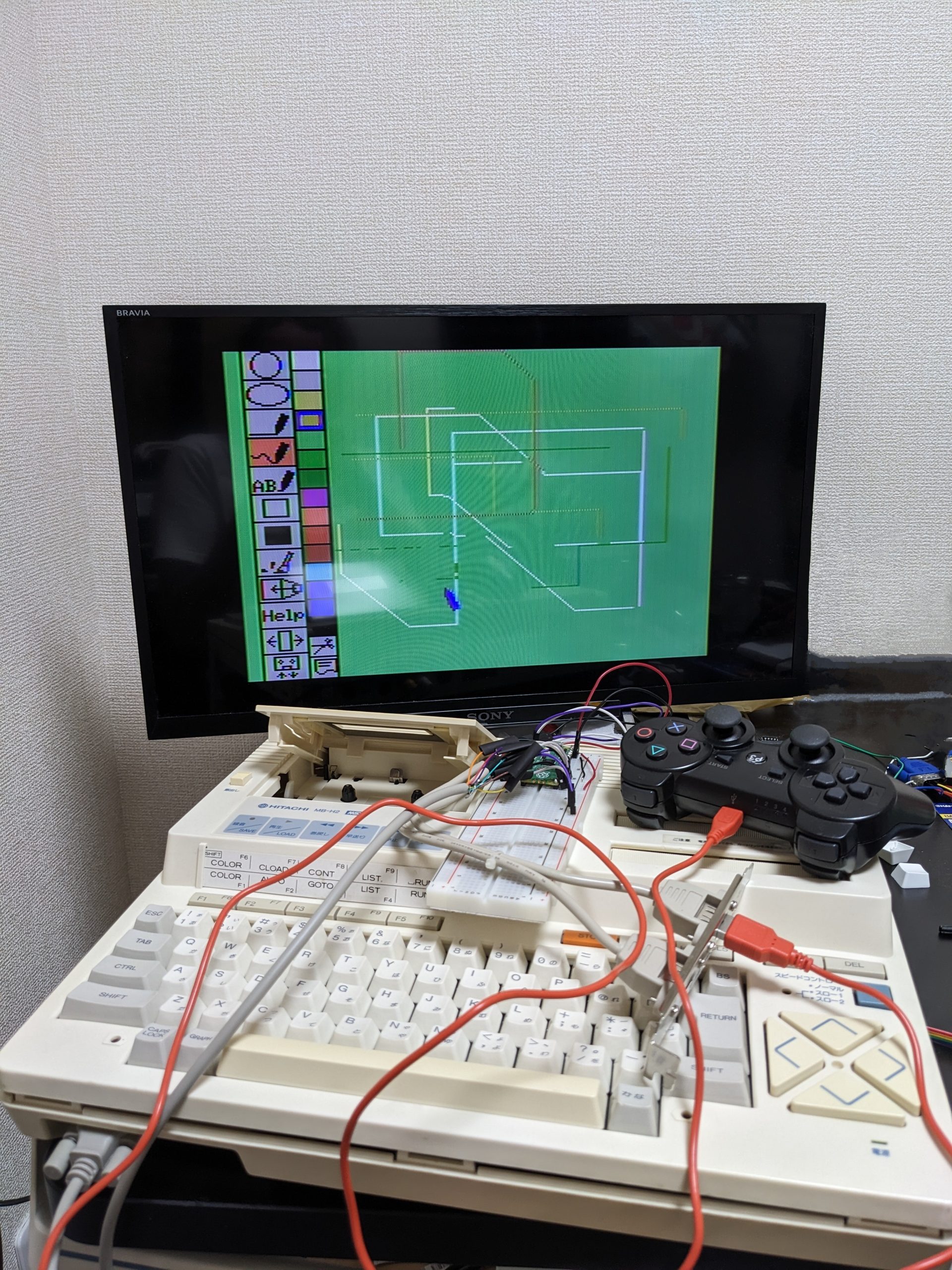
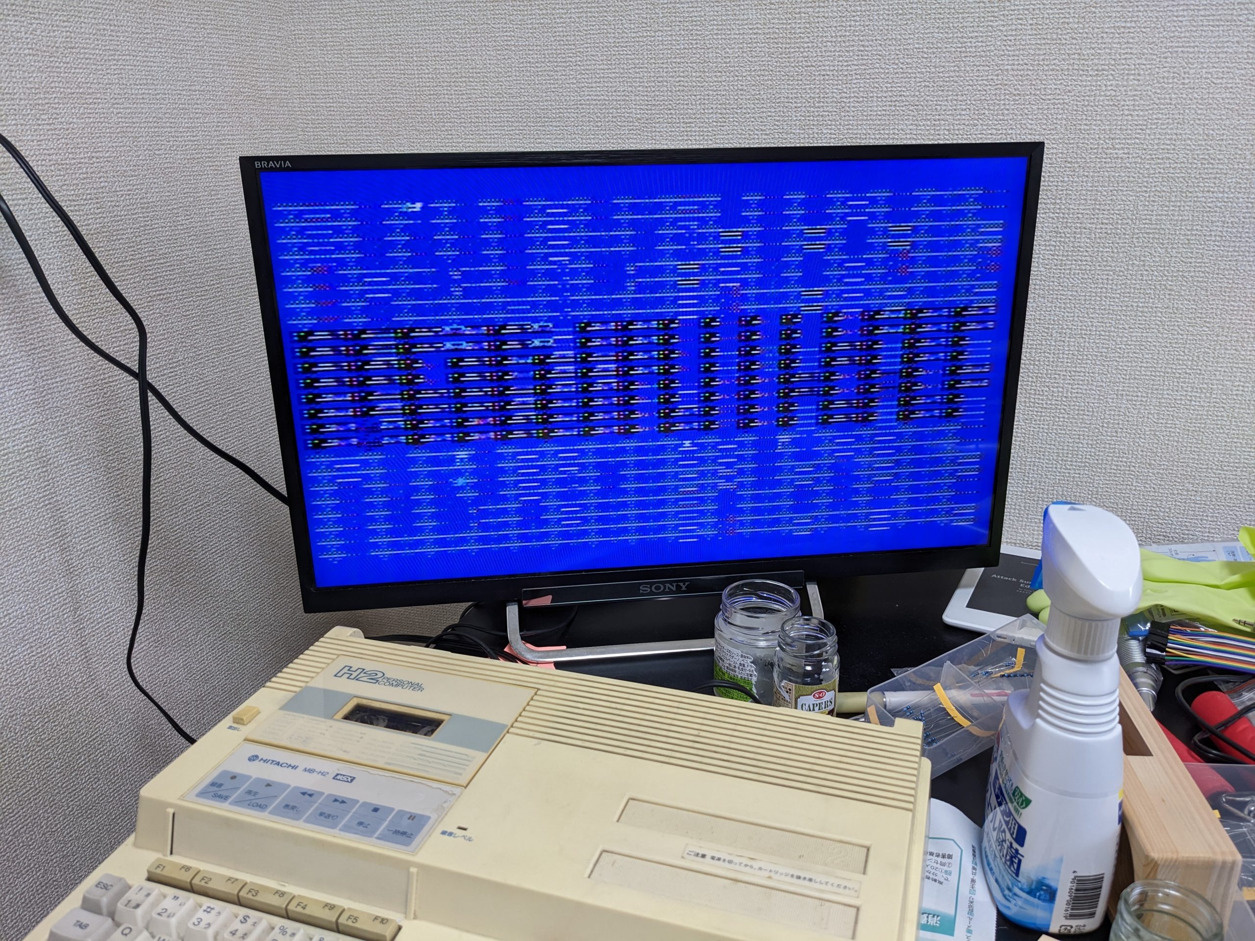
Yes. Here’s a pic of my trusty Hitachi MB-H2 MSX running its built-in sketch program, controlled through the fake PS3 controller. (Sorry, the computer’s still open from the probing I did earlier.)
The USB port is a PC part that I found at my local Hard Off. The RS232 cable is also from Hard Off. In fact, the fake PS3 controller is also from Hard Off! The USB cable is from my own cable collection.
Totally off-topic, but there’s a spot in this pic that has been cleaned up using my Pixel phone’s magic eraser. Can you see where it is? (I didn’t touch it up in an image editor afterwards.)
Pacman <3
Problems
Plugging our contraption into the joystick port while the MSX is running crashes the machine! The screen goes very slightly dark for a split second too. Probably in-rush current. I’m pretty sure I blew my multimeter’s (200 mA) fuse trying to measure the current. Laff. (Having the controller already plugged in before powering on the computer works fine.)
Source code
Replace your Pico-PIO-USB/examples/capture_hid_report.c with the following code, (re-)make, flash, and you’re set. (I’m basing my modifications on git commit d00a10a8c425d0d40f81b87169102944b01f3bb3.)
#include <stdio.h>
#include <string.h>

#include "pico/stdlib.h"
#include "pico/multicore.h"
#include "pico/bootrom.h"

#include "pio_usb.h"

#define GAMEPAD_REPORT_ID 1

// 0x1: L2
// 0x2: R2
// 0x4: L1
// 0x8: R1
// 0x10: Triangle
// 0x20: Circle
// 0x40: X
// 0x80: Square?
// 0x100: ?
// 0x200: ?
// 0x400: R3
// 0x800: Start
// 0x1000: Up
// 0x2000: Right
// 0x4000: Down?
// 0x8000: Left?

#define BUTTON_UP 0x1000
#define BUTTON_DOWN 0x4000
#define BUTTON_LEFT 0x8000
#define BUTTON_RIGHT 0x2000
#define BUTTON_A 0x20
#define BUTTON_B 0x40
#define BUTTON_A_ALT 0x10
#define BUTTON_B_ALT 0x80

#define BUTTON_UP_PIN 16
#define BUTTON_DOWN_PIN 17
#define BUTTON_LEFT_PIN 18
#define BUTTON_RIGHT_PIN 19
#define BUTTON_A_PIN 20
#define BUTTON_B_PIN 21

static usb_device_t *usb_device = NULL;

void core1_main() {
  sleep_ms(10);

  // To run USB SOF interrupt in core1, create alarm pool in core1.
  static pio_usb_configuration_t config = PIO_USB_DEFAULT_CONFIG;
  config.alarm_pool = (void*)alarm_pool_create(2, 1);
  usb_device = pio_usb_host_init(&config);

  //// Call pio_usb_host_add_port to use multi port
  // const uint8_t pin_dp2 = 8;
  // pio_usb_host_add_port(pin_dp2);

  while (true) {
    pio_usb_host_task();
  }
}

static void gpio_setup()
{
  gpio_init(BUTTON_UP_PIN);
  gpio_init(BUTTON_DOWN_PIN);
  gpio_init(BUTTON_LEFT_PIN);
  gpio_init(BUTTON_RIGHT_PIN);
  gpio_init(BUTTON_A_PIN);
  gpio_init(BUTTON_B_PIN);

  gpio_set_dir(BUTTON_UP_PIN, GPIO_IN);
  gpio_set_dir(BUTTON_DOWN_PIN, GPIO_IN);
  gpio_set_dir(BUTTON_LEFT_PIN, GPIO_IN);
  gpio_set_dir(BUTTON_RIGHT_PIN, GPIO_IN);
  gpio_set_dir(BUTTON_A_PIN, GPIO_IN);
  gpio_set_dir(BUTTON_B_PIN, GPIO_IN);

  gpio_put(BUTTON_UP_PIN, 0);
  gpio_put(BUTTON_DOWN_PIN, 0);
  gpio_put(BUTTON_LEFT_PIN, 0);
  gpio_put(BUTTON_RIGHT_PIN, 0);
  gpio_put(BUTTON_A_PIN, 0);
  gpio_put(BUTTON_B_PIN, 0);
}

int main() {
  // default 125MHz is not appropreate. Sysclock should be multiple of 12MHz.
  set_sys_clock_khz(120000, true);

  stdio_init_all();
  printf("hello!");

  sleep_ms(10);

  multicore_reset_core1();
  // all USB task run in core1
  multicore_launch_core1(core1_main);

  gpio_setup();

  while (true) {
    if (usb_device != NULL) {
      for (int dev_idx = 0; dev_idx < PIO_USB_DEVICE_CNT; dev_idx++) {
        usb_device_t *device = &usb_device[dev_idx];
        if (!device->connected) {
          continue;
        }

        // Print received packet to EPs
        for (int ep_idx = 0; ep_idx < PIO_USB_DEV_EP_CNT; ep_idx++) {
          endpoint_t *ep = pio_usb_get_endpoint(device, ep_idx);

          if (ep == NULL) {
            break;
          }

          uint8_t temp[64];
          int len = pio_usb_get_in_data(ep, temp, sizeof(temp));

          if (len > 0) {
            if (temp[0] == GAMEPAD_REPORT_ID) {
              uint16_t button_state = temp[2] << 8 | temp[3];
              if (button_state & BUTTON_UP) {
                gpio_put(BUTTON_UP_PIN, 0);
                gpio_set_dir(BUTTON_UP_PIN, GPIO_OUT);
                printf("BUTTON_UP_PIN\n");
              } else {
                gpio_set_dir(BUTTON_UP_PIN, GPIO_IN);
              }

              if (button_state & BUTTON_DOWN) {
                gpio_put(BUTTON_DOWN_PIN, 0);
                gpio_set_dir(BUTTON_DOWN_PIN, GPIO_OUT);
                printf("BUTTON_DOWN_PIN\n");
              } else {
                gpio_set_dir(BUTTON_DOWN_PIN, GPIO_IN);
              }

              if (button_state & BUTTON_LEFT) {
                gpio_put(BUTTON_LEFT_PIN, 0);
                gpio_set_dir(BUTTON_LEFT_PIN, GPIO_OUT);
                printf("BUTTON_LEFT_PIN\n");
              } else {
                gpio_set_dir(BUTTON_LEFT_PIN, GPIO_IN);
              }

              if (button_state & BUTTON_RIGHT) {
                gpio_put(BUTTON_RIGHT_PIN, 0);
                gpio_set_dir(BUTTON_RIGHT_PIN, GPIO_OUT);
                printf("BUTTON_RIGHT_PIN\n");
              } else {
                gpio_set_dir(BUTTON_RIGHT_PIN, GPIO_IN);
              }

              if (button_state & BUTTON_A || button_state & BUTTON_A_ALT) {
                gpio_put(BUTTON_A_PIN, 0);
                gpio_set_dir(BUTTON_A_PIN, GPIO_OUT);
                printf("BUTTON_A_PIN\n");
              } else {
                gpio_set_dir(BUTTON_A_PIN, GPIO_IN);
              }

              if (button_state & BUTTON_B || button_state & BUTTON_B_ALT) {
                gpio_put(BUTTON_B_PIN, 0);
                gpio_set_dir(BUTTON_B_PIN, GPIO_OUT);
                printf("BUTTON_B_PIN\n");
              } else {
                gpio_set_dir(BUTTON_B_PIN, GPIO_IN);
              }
            }
          }
        }
      }
    }
    stdio_flush();
    sleep_us(10);
  }
}
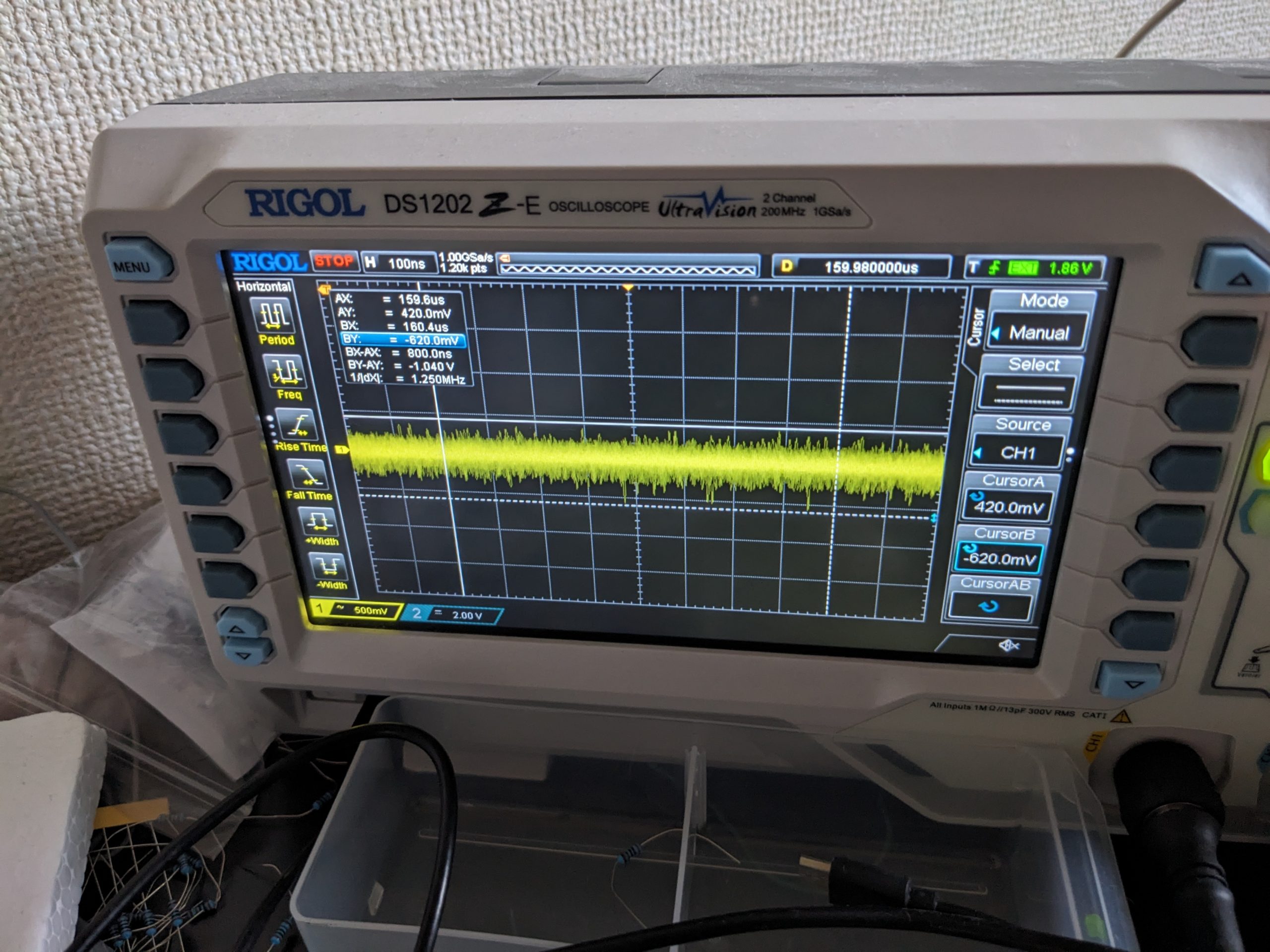
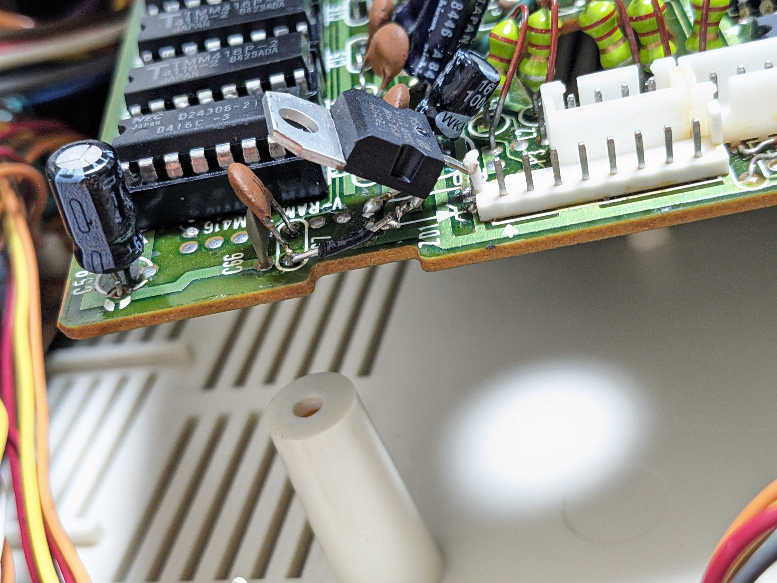
I bought another Hitachi H2 MSX last year, mostly because I wanted the manual, which I’ve scanned. Unfortunately for my free time but fortunately for my, um, education in retro computing, this computer had issues with its video RAM. Often, the computer would boot up with a garbled screen. Resetting after a couple minutes would usually fix the issue. The video RAM is made by Toshiba, and is called TMM416P-2 (also marked 4116-2). If you have this memory, I’d recommend you look out for issues, because all eight ICs had the same issue, namely: crazy-ass noise on the -5V line. (How much noise is “crazy-ass” noise? In this case, it’s +-3V.) The noise sort of comes and goes, or at least gets stronger and weaker, randomly, which made it too hard for me to find a combination of capacitors to tame it. (Though it’s more likely to be present after turning the computer on after a long while.) I ended up socketing them all, replacing one that unfortunately died during the very professional desoldering process, and added 103 ceramic capacitors to (almost) every one, between the -5 and GND pins, which seems to have a slight positive effect. (The bottom part of the case has a hook that requires some clearance and prevents two of the chips from getting their capacitor.) I also replaced the zener diode with a 7905, which fit perfectly after bending the legs a little bit.
Details
The -5V rail for the 4116 VRAM chips is generated using a zener diode. Replacing this, or the capacitor on the rail, unfortunately didn’t have any effect. Hmm, odd!
Next, I decided to desolder the -5V pin on the first 4116 IC, and drive it using my own known good -5V supply (using a standard 7905 regulator). Result: noise both on the first chip and all the others. Hmm, odd!
Next, I did this for the rest of the 4116 ICs, and was able to see that each and every one generates noise.
Next, I decided to desolder all of them and individually test them on my 4116 tester. (They still produced the noise while in the tester.) I decided to desolder all of them because the H2 seemed to support 4416 ICs for the video RAM, and I happened to have some of those that were waiting to be put to use. I.e., there are holes of the right size, right next to the VDP, and the silkscreen on those holes says “TMS4416”. ;)
Well, today’s lesson is, do not necessarily trust the silkscreen. The TMS9928A doesn’t even support 4416 VRAM! The holes where the data pins go didn’t even have any traces on them. The TMS9928A can be made to support 4416 RAM using a custom circuit, though. Maybe I should have implemented this circuit. I even bought the two required parts! But then decided against it for complexity management reasons.
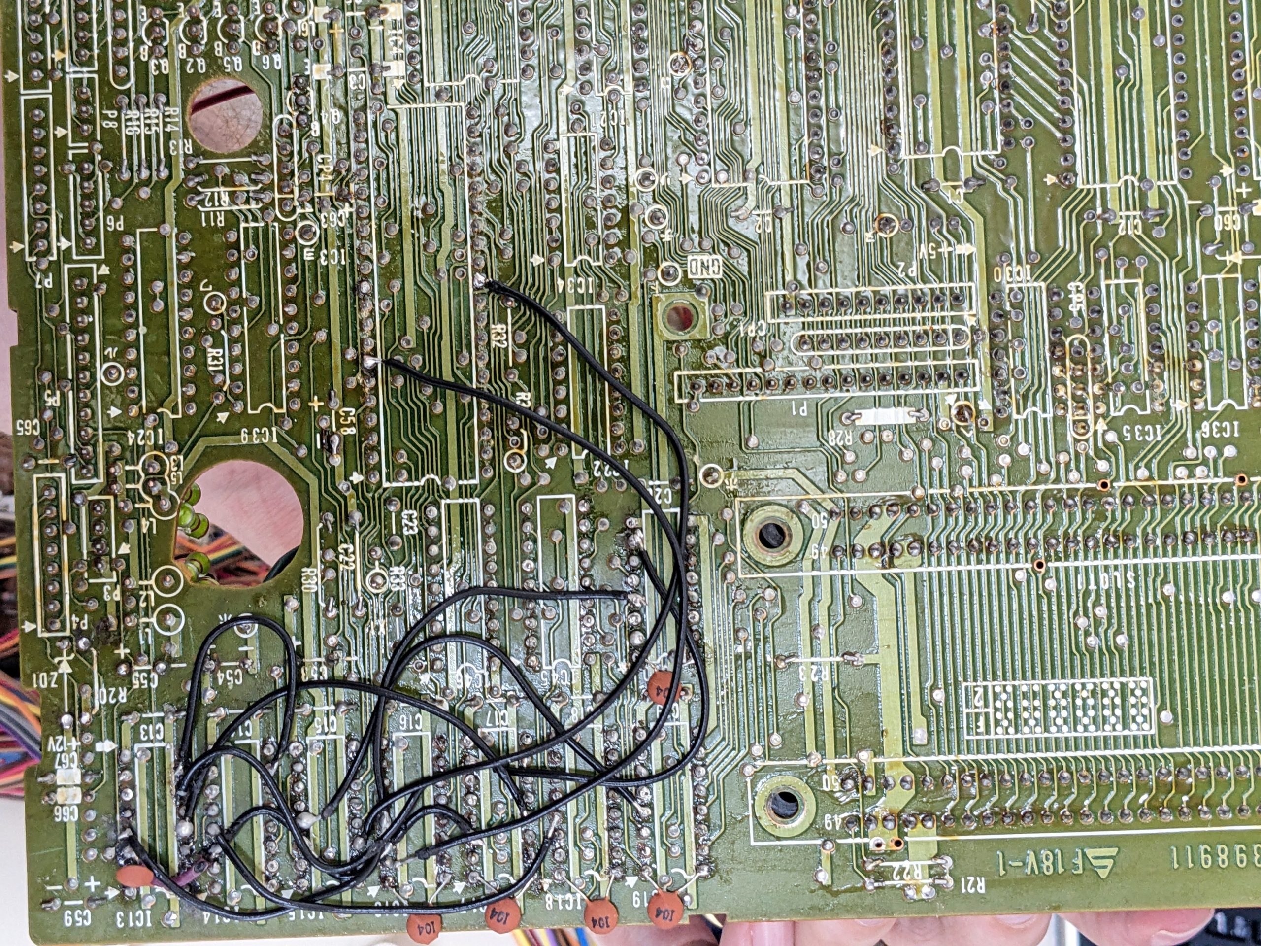
Unfortunately, expecting to be able to use the 4416 slots, I had desoldered the original VRAM ICs in a rather brutish manner, losing vias and traces in the process, which meant that I needed to add a bunch of bodge wires to get them to work again. At least the bodge wires aren’t too complex to figure out, if at some point one of them decides to become loose again. I ended up keeping the original, noisy, RAM chips. But since they’re now all socketed, it shouldn’t be too hard to replace them at some point, if necessary.
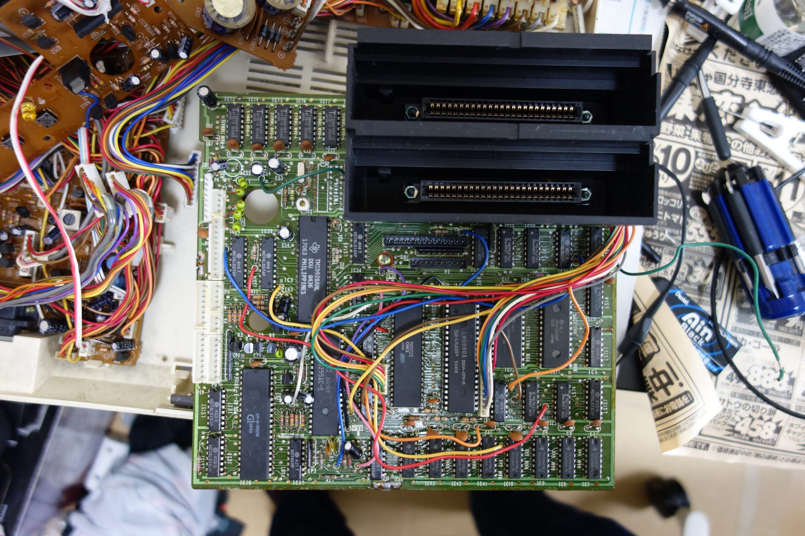
Pictures
Garbled screenHitachi MB-H2 logic board from above. The misleading silkscreen is in the top left, above the TMS9928ANL VDP.Example with a lot of noiseAnd an example with a lot less. (This picture is from six months ago. It’s entirely possible that I had extra capacitors for this shot.)TMM416P-2 noise closeup. Intensity varies. Here it’s about 3V peak-to-peak.TMM416P-2 noise closeup, one more example.
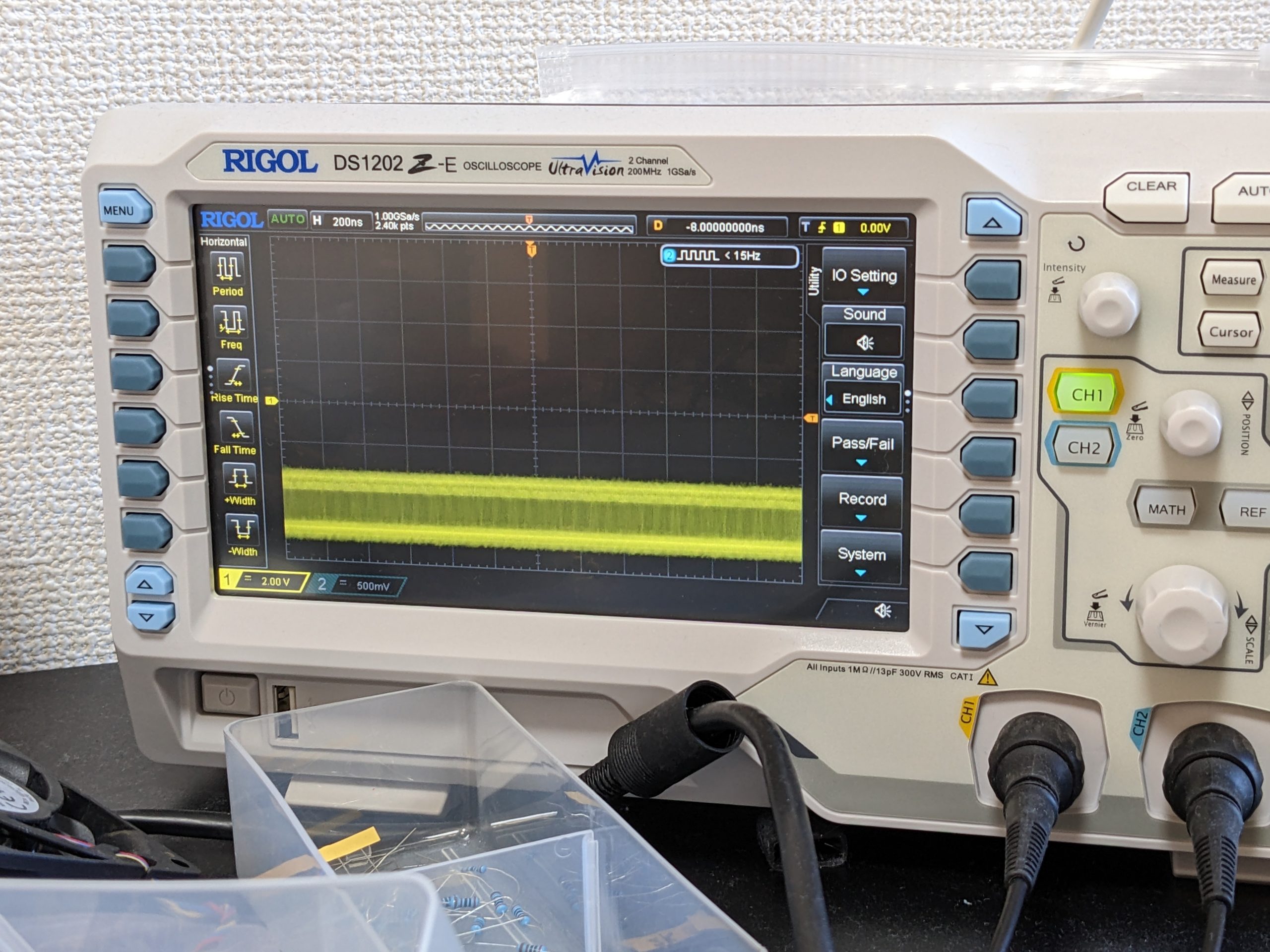
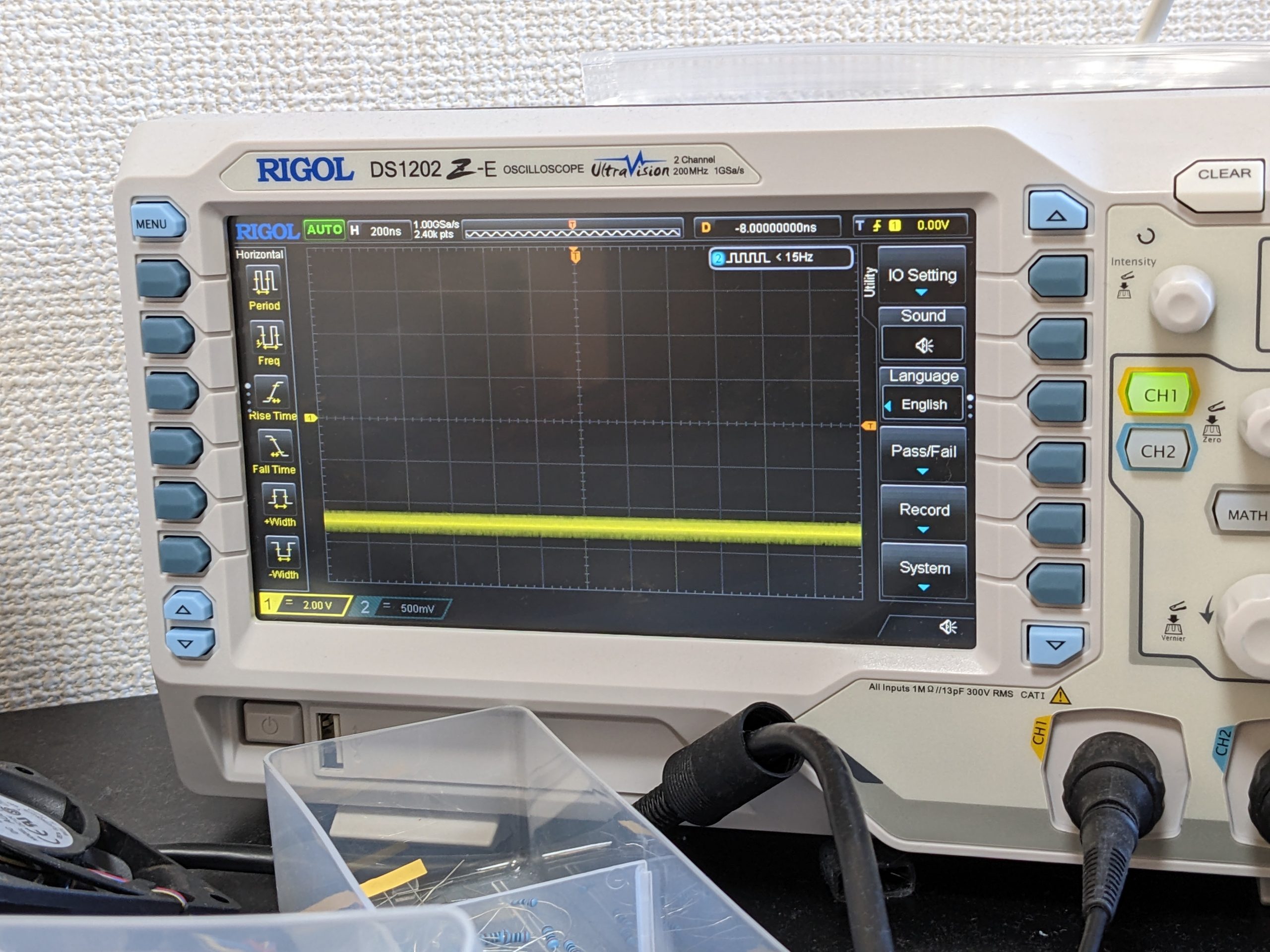
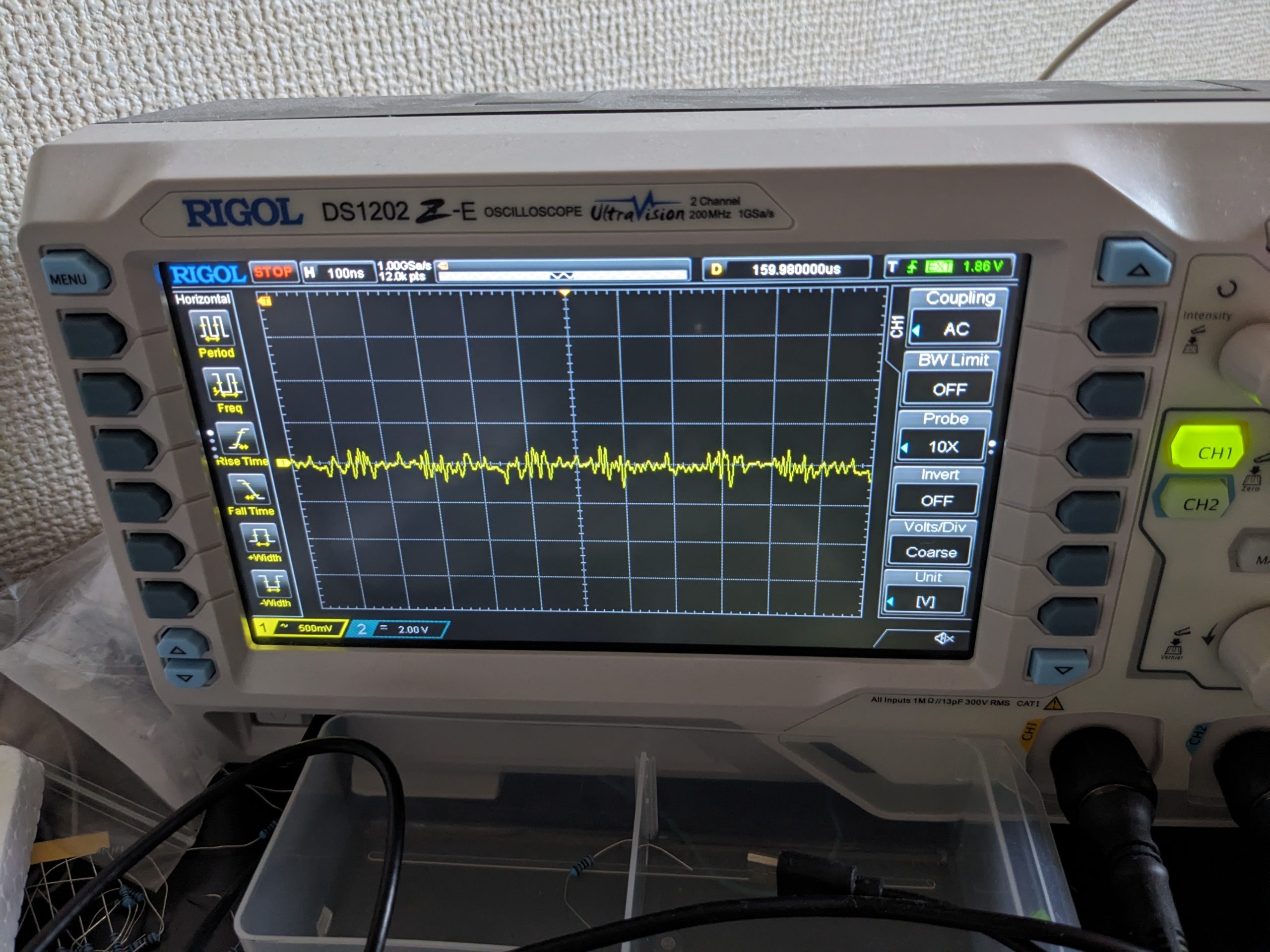
After
Noise after “completion” of this repair (note: using AC coupling here). Note that noise intensity has always been a bit random, so I this can’t be taken as proof that adding 103 capacitors to each chip is going to help in any case, and I am not too interested in performing rigorous testing. Anecdotally, I haven’t seen any garbled screens yet after the “repair”!Noise closeup (note: using AC coupling here)Check out this 7905’s limbo dance moves
Before looking at the picture of the bodge wires below, please keep in mind that it is rude to stare.
Hi, just a quick thing that may be useful if you’re trying to save memory while using libwebp to encode a monochrome image.
We assume that you already have the monochrome data, and you just want to encode it. Your data size is width*height*1, and is 100% equivalent to the Y channel in YUV.
Allocating a bunch of memory (width*height/2) for the UV part would be silly, but looks like it’s required, right?
Well, we can actually get away with just width/2, by doing this:
    picture.y = y_data; // straightforward
    picture.y_stride = width; // straightforward
    picture.u = dummy_uv_data; // array of length width/2 full of 0x80 bytes
    picture.v = dummy_uv_data; // it's the same array!
    picture.uv_stride = 0; // stride is 0! this means we'll always read UV from the same location for every single pixel row
BTW, you can generate your y_data with the following ImageMagick command:
convert test.jpg y:test.y
Below is the full code demonstrating the use of this trick. Note that the code is about 90% generated by ChatGPT, and I haven’t cleaned it up beyond the minimum necessary to get it to work. Don’t forget to adjust the width and height variables to match your input image.
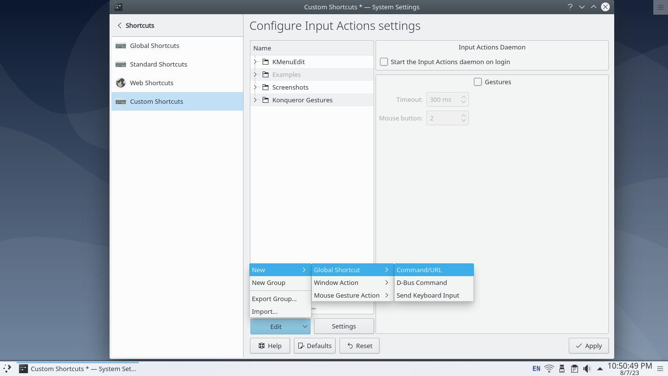
Ah yes, printf debugging. If you’re like me and occasionally need to place a dozen “got here”s at once, you may find this, or something like this helpful.
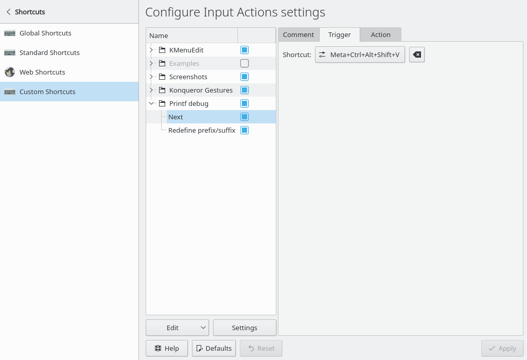
You need some kind of facility to create global shortcuts. If you, like many sensible people in the world, are a KDE user, you’ll find such a facility right in the settings:
Define two shortcuts, perhaps name them “Next” and “Redefine”. Perhaps Meta+Ctrl+Alt+Shift isn’t very ergonomic, but it’s probably unique at least.
Next, we’ll add actions. “Next” should type something like ‘printf(“Got here23”);’, and “redefine” allows you to change the ‘printf(“Got here’ prefix and the ‘”);’ suffix.
Here are two example shell scripts to accomplish this. Dependencies: xclip, xdotool. (Note: these scripts probably won’t work on Wayland, but I’d assume there are Wayland-compatible replacements for these two programs.)
#!/bin/bash

cd $(dirname -- "${BASH_SOURCE[0]}")
touch prefix_or_suffix
prefix_or_suffix=$(cat prefix_or_suffix)
if [ "$prefix_or_suffix" == 1 ]; then
    xclip -o -selection primary > suffix
    prefix_or_suffix=0
else # 0 or blank or junk
    xclip -o -selection primary > prefix
    prefix_or_suffix=1
fi
echo -n $prefix_or_suffix > prefix_or_suffix
echo -n 1 > next_i
If your system is kind of slow and xdotool’s output gets chopped up somehow, maybe try xdotool key –delay 50. You could also do echo $string_to_type | xclip, and then xdotool to send Ctrl-V in order to paste. That might be a little faster for long strings.
Here’s a short video clip that shows how this works:
By the way, this is the 100th post on this blog. :O

