I recently had a look (multiple long looks) at a Commodore PET 2001 (with the ~first version of BASIC etc.) and a special character ROM with Japanese katakana instead of lower-case characters. I was told it had worked in around 2000 when it was last turned on. I went right in without knowing much about the Commodore PET.
Wobbly screen, junk characters on boot
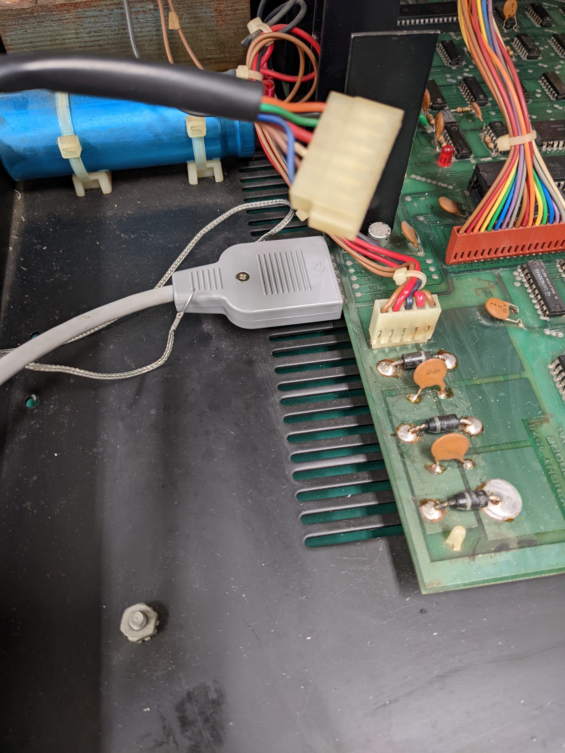
The wobbly/unstable/warped screen was caused by an oxidized and slightly broken molex connector supplying power to the board. This caused the voltages to jump between 4-5 volts multiple times per second. Well, nothing’s going to work that way. (Ideally I would have fixed this first, but I’d already noticed a bunch of other bad connections and didn’t think the molex connector would go bad.)
Stable screen, junk characters on boot
All chips that cost more than a couple cents (don’t know the prices in 1977 of course) were socketed. But boy, these are bad sockets. The one redeeming feature of the sockets that were used by Commodore at this time is that it’s easy to check if the inserted chip is making a connection with the socket. Just put your multimeter in continuity mode, one multimeter probe on the chip’s pin, and the other on the slightly exposed metal part belonging to the socket. No beep — bingo, that needs to be fixed.
This isn’t my machine and I’m not allowed to use contact cleaner (except IPA of course). I’m sure that contact cleaner would have helped here though. Anyway, not all of the bad connections were due to oxidization as far as I can tell — it seems like the socket and the pin just aren’t making physical contact, even after judicial use of IPA.
In these cases you can either replace the bad socket, or you can try to bend the chip’s legs to get better contact. I’d advise you not to do that with the chips in the PET; most of them were rather brittle in my case. Another thing you can do, and which I did here, is to put a new socket right on top of the existing socket. In most cases that’ll improve things immediately.
So I did that on all RAM chips after testing continuity almost everywhere (there was at least one pin that didn’t make contact on most chips) and all ROM chips except one (one didn’t have any bad contacts for some reason. The middle one, so maybe that one was more protected from the elements compared to ones closer to the edge?), and one of the 6520s. For the CPU and other chips, just re-seating did the trick.

One thing you have to know about the PET 2001 is that it’s possible to boot with just 2K (or even 1K?) of RAM. So make sure to put working RAM (making good contact) into the leftmost RAM sockets. If you have slightly faulty RAM, it doesn’t matter so much if you have that in the sockets beyond 2K. Your PET (if it boots) will tell you how many bytes of RAM you have free on boot. If it says 7167 bytes (on an 8K model), that means your RAM is probably fine. If it’s less than that, you probably have faulty RAM somewhere. (Broken RAM that misbehaves grossly may cause problems though.)
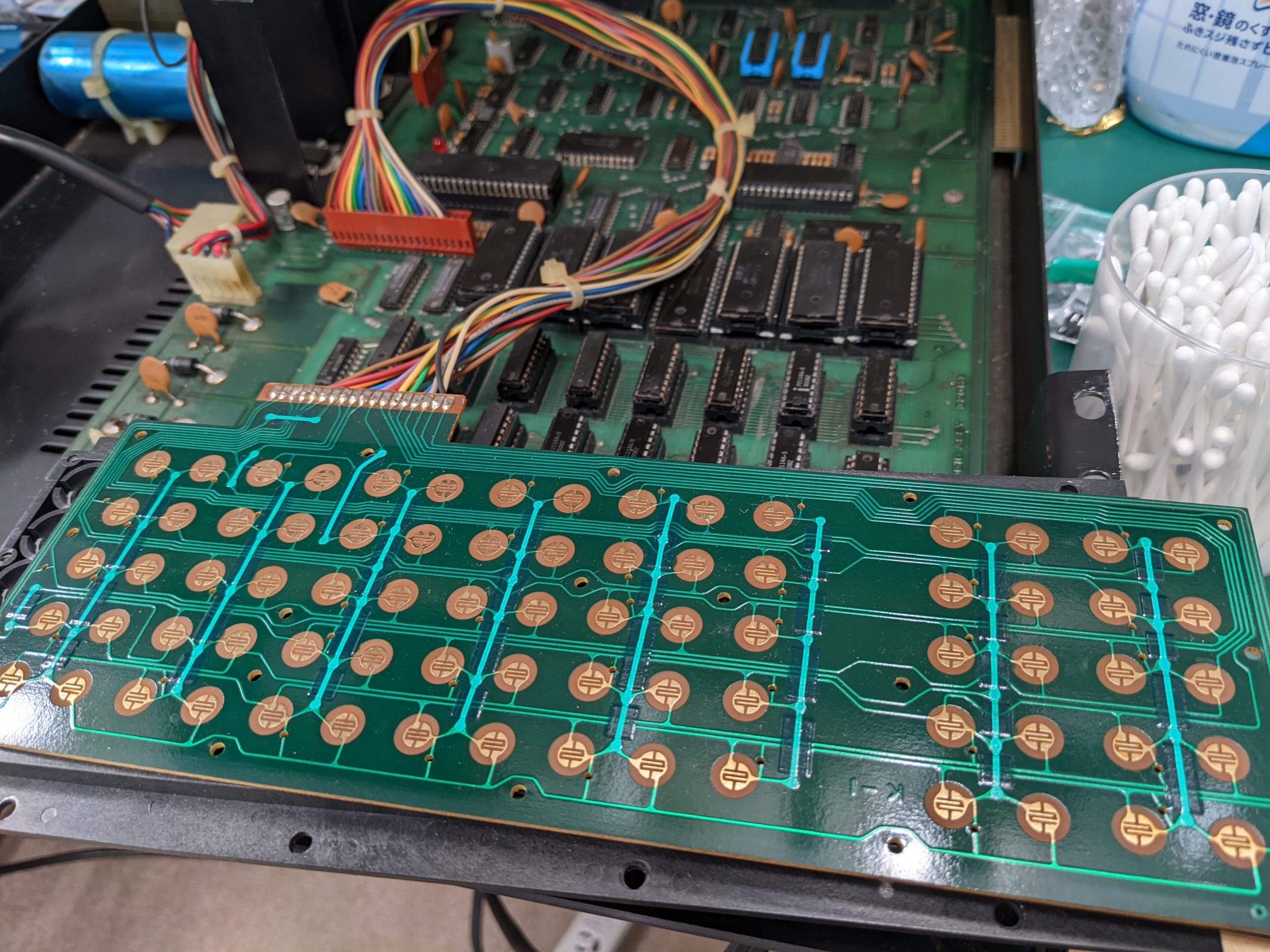
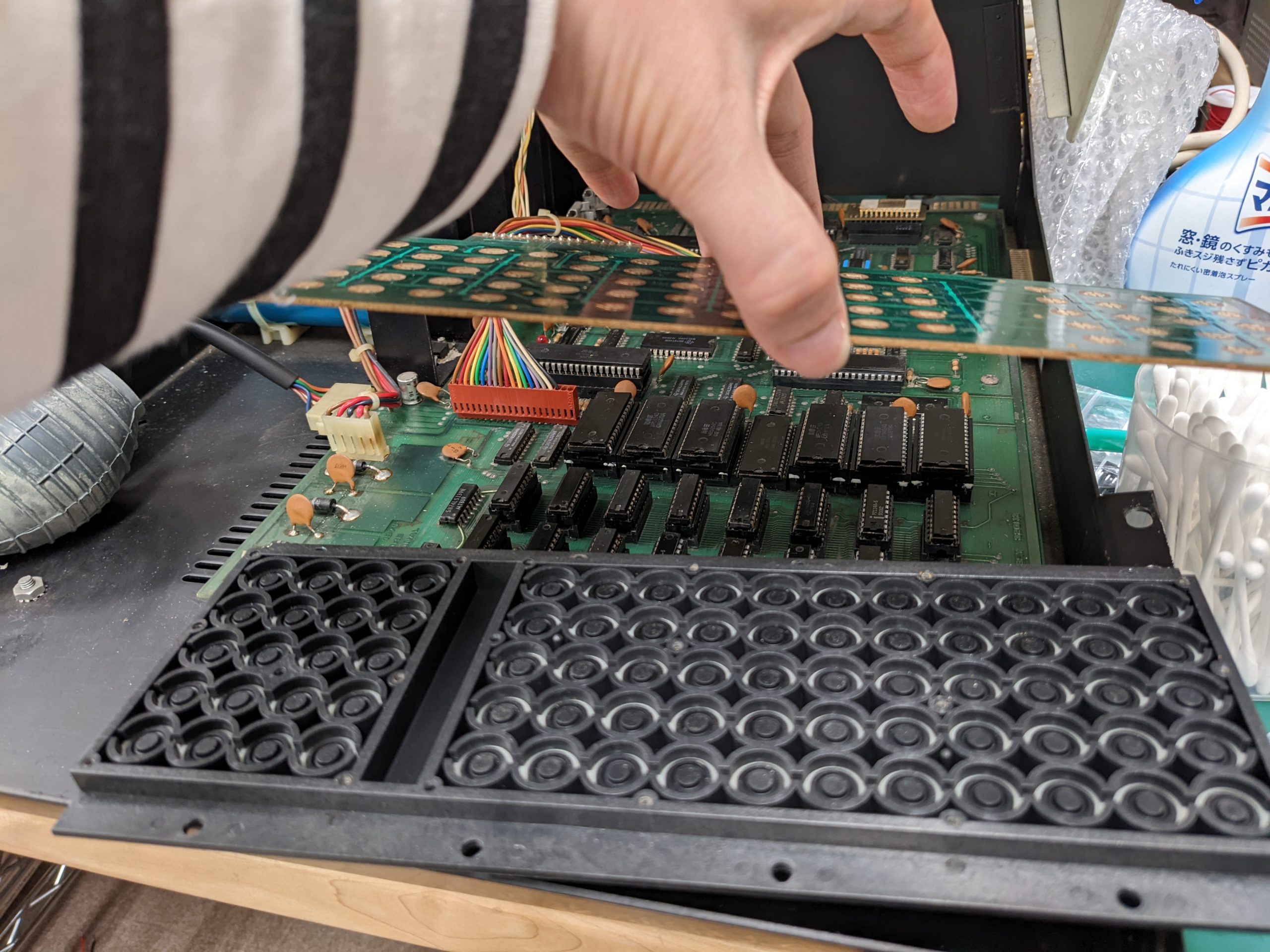
Keyboard fixes
If your PET has successfully booted, you should test all keys. If there are keys that don’t appear to work, try holding the key down for a little, or repeatedly pressing the key. If none of that helps, you will need to take apart the keyboard and clean it up using IPA. That fixed all problems for me.
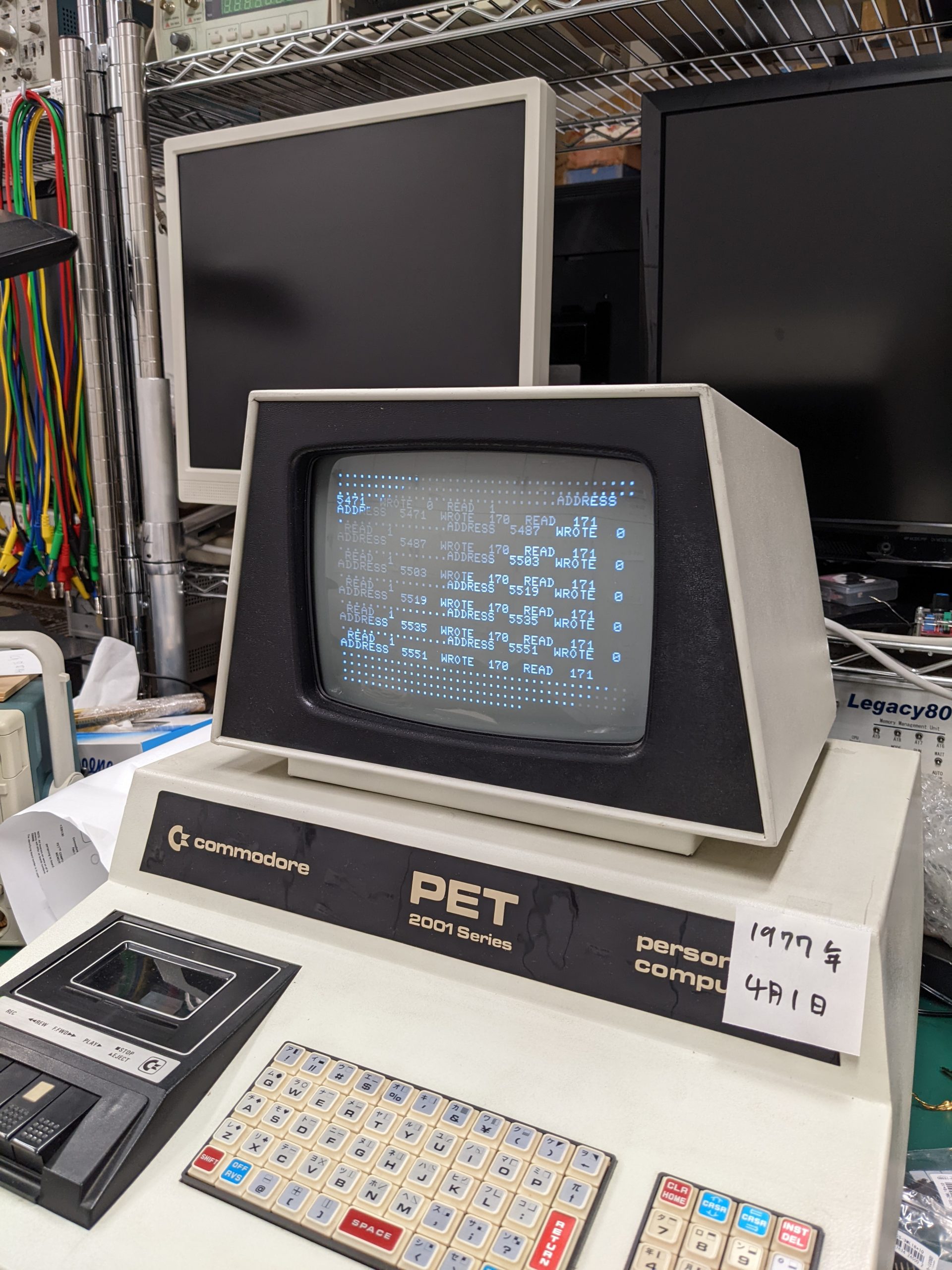
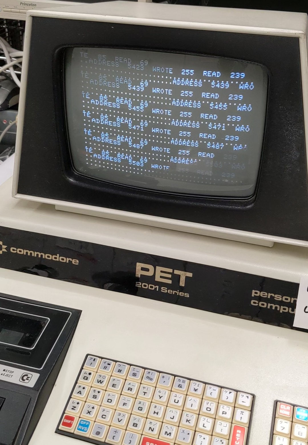
Testing RAM and ROM with a short BASIC program
If your PET has successfully booted, you may want to test your RAM and ROM chips. I found a BASIC script on the web to test RAM, but wasn’t able to run it back when my PET reported it only had 363 (or so) bytes free — the program was just too long. Original program from https://www.commodore.ca/commodore-manuals/commodore-pet-memory-test/. Here’s my modified version, which will work with much less RAM, has some visual feedback and isn’t that tough to type in.
5 INPUTA,B
20 FORI=ATOB
21 FORY=1TO4
22 READN
23 POKEI,N:X=PEEK(I)
24 IFX=NTHEN26
25 GOSUB200
26 NEXT
27 RESTORE
30 DATA0,85,170,255
120 PRINT "."
121 NEXT
130 PRINT "DONE"
140 END
200 PRINT "ADDRESS ";I;" WROTE ";N;" READ ";X
210 RETURN
Note that the PET firmware will place the BASIC code at address 1025+, variables go between 1946-2071, and arrays go from 2072-2231. As long as our BASIC code doesn’t use arrays, not too many variables, and isn’t too long, the system won’t need to access memory beyond 2K. So it’s safe to run this program on all RAM, from 2048 to 8191. (It’s pretty slow BTW, you may want to run it multiple times, in 2K steps.)
If you get errors, check the schematics for your board revision, re-test continuity between chip and socket on the supposedly faulty chip, and if there’s no connection error, replace it.
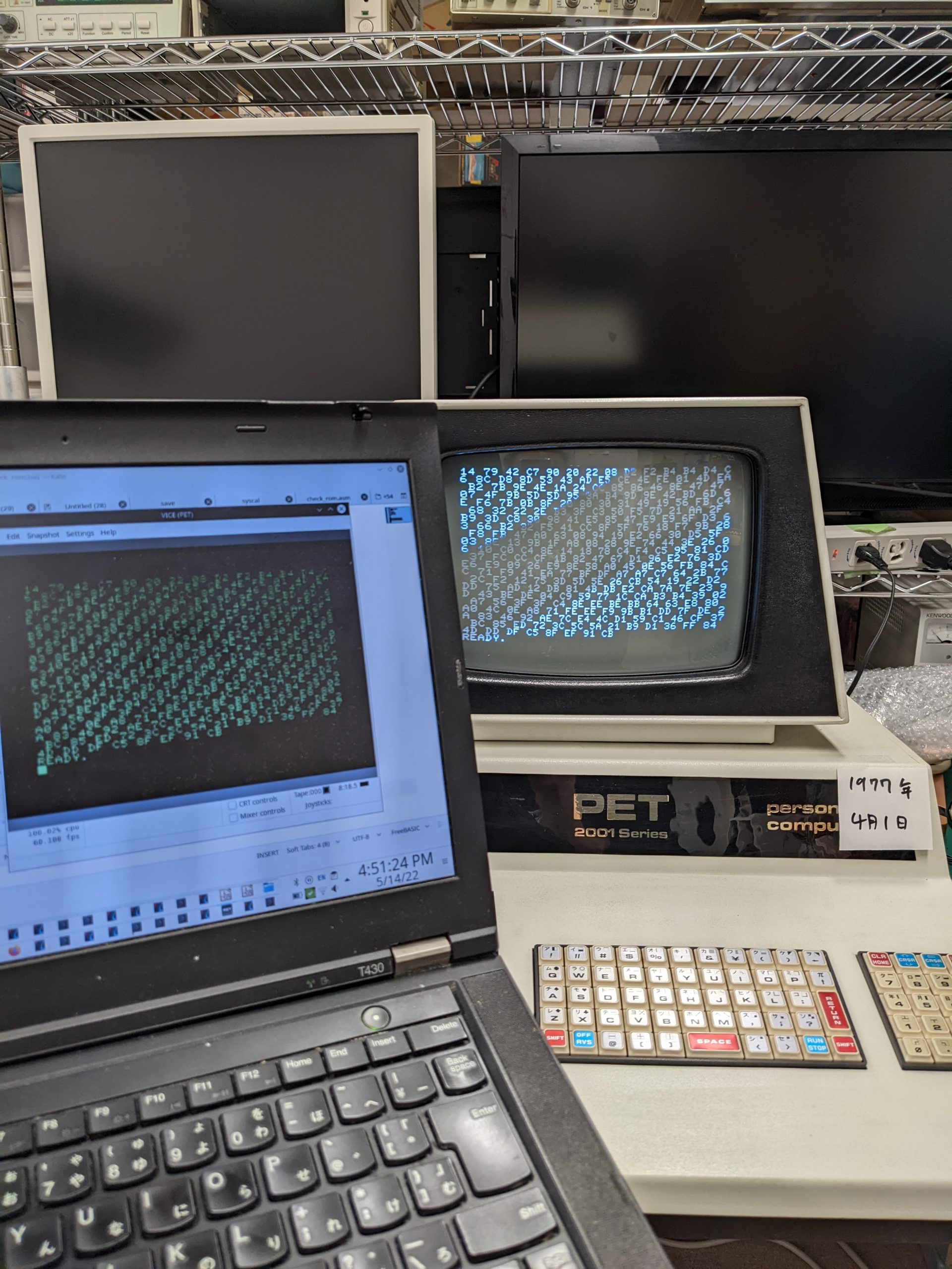
Here’s the ROM test, in ASM and BASIC (with data lines). On the PET, the ROM isn’t accessible from BASIC using PEEK, so assembly is required. Make sure you don’t make any mistakes when typing in the data lines.
.ORG = $1000
START:
LDA #0
LDY #$D0 ; stop when INC_ADDRESS+2 reaches this value
LOOP:
CLC ; clear carry flag, otherwise we'd add unneeded +1s
INC_ADDRESS:
ADC $C800 ; add contents of memory address $C800 to A (this address will be modified below)
JSR PRINT_HEX ; print out checksum for every added byte
INC INC_ADDRESS+1 ; increments insignificant byte
BNE LOOP ; if that address hasn't overflowed back to 0, go to LOOP
INC INC_ADDRESS+2 ; increments significant byte
CPY INC_ADDRESS+2 ; compare significant byte with Y register (into which we loaded the significant byte of the end address earlier)
BNE LOOP ; if unequal, go to LOOP
; JSR PRINT_HEX ; if we blazed past both BNEs then we're done so output checksum ; commented out because we currently print out the checksum for every added byte
RTS ; return from subroutine

PRINT_HEX:
PHA ; copy A to stack
LSR ; shift right 4 times so we get significant nibble
LSR
LSR
LSR
JSR PRINT_NIBBLE
PLA ; get fresh copy of A from stack
PHA ; and also write it back on stack
AND #$0f ; get lower nibble
JSR PRINT_NIBBLE
LDA #32 ; code for space
JSR $FFD2 ; print a space
PLA
RTS

PRINT_NIBBLE:
CMP #10 ; if we're >= 10
BCS HEX_ABCDEF ; branch
CLC ; clear carry flag, otherwise we'd add unneeded +1s
ADC #48 ; otherwise, add 48 to turn into a number
JSR $FFD2 ; print number
RTS ; return
HEX_ABCDEF: ; this is the a-f branch
CLC ; clear carry flag, otherwise we'd add unneeded +1s
ADC #55 ; we're at range 10-15 but want range 65-70, so add some
JSR $FFD2 ; print a-f
RTS
BASIC:
10 t=4096
15 input "decimal msb of start address"; sa
16 input "decimal msb of end address "; ea
17 input "carry over "; co
20 read x
30 if x=-1 then sys 4096:end
40 if x=-2 then poke t,sa:goto 80
50 if x=-3 then poke t,ea:goto 80
60 if x=-4 then poke t,co:goto 80
70 poke t,x
80 t=t+1
90 goto 20
1000data169,-4,160,-3,24,109,0,-2,32,25,16,238,6,16,208,244
1010data238,7,16,204,7,16,208,236,96,72,74,74,74,74,32,47
1020data16,104,72,41,15,32,47,16,169,32,32,210,255,104,96,201
1030data10,176,7,24,105,48,32,210,255,96,24,105,55,32,210,255
1040data96
1050data-1
Here’s a very lazy script (bin2data.sh) to assemble (using acme) and generate a simple BASIC loader:
#!/bin/bash

echo rem assuming compilation with acme --setpc 4096 -o foo check_rom.asm
echo
echo

echo '10 t=4096'
echo '20 read x:if x<>-1 then poke t,x:t=t+1:goto 20'
(od -Anone -tx1 $1 | perl -pe 's/([0-9a-fA-F]{2})/hex($1).","/eg' | sed -r -e 's/^/data/' -e 's/,$//'; echo 'data -1') | nl -i 10 -v 1000 -nln | sed -e 's/ //g' -e 's/ //g'
Here’s how to assemble using acme and use the bin2data.sh script:
acme --setpc 4096 -o check_rom.bin check_rom.asm; bin2data.sh check_rom.binNote that the BASIC listing above is almost identical to the output of the assembler script, except that I manually modified the output to place -4, -3, and -2 in the DATA lines. This is where the start/end addresses and the carry over go.
What this program does is sum up all values in the ROM. It also prints out the intermediate sum for each byte. Note that in the above loader, we poke the machine code into addresses 4096+. If you are on a 4K PET, that will not work. Just modify the .ORG, –setpc, and t=4096 lines in the assembly source, acme command line, and bin2data.sh, respectively.
The ROMs on my machine are 2K each. Their addresses are 0xC000-0xC7FF (most significant byte in decimal: 192), 0xC800-0xCFFF (200), 0xD000-0xD7FF (208), 0xD800-0xDFFF (216), 0xE000-0xE7FF (224), 0xF000-0xF7FF (240), 0xF800-0xFFFF (248).
So you enter 192 for the start address, 200 for the (non-inclusive) end address, 0 for carry over. On my machine (and in VICE), the last few numbers are 8F EF 91 CB. Note: the ROMs at https://www.zimmers.net/anonftp/pub/cbm/firmware/computers/pet/index.html yield different checksums for this region.
I had the same checksums as the emulator for C000-C7FF, C800-CFFF, D000-D7FF, D800-DFFF, E000-E7FF, but different values for F000-F7FF and F800-FFFF. However, the checksums for F000 to FFFF were identical with rom-1-f000.901439-04.bin and rom/rom-1-f800.901439-07.bin downloaded from the above site.
Here’s a very lazy script to compute the checksums using perl:
od -Anone -tx1 roms/rom-1-f800.901439-07.bin | perl -ne 'while (s/([0-9a-fA-F]{2} ?)//) { $sum = ($sum + hex($1)); printf("%x\n", $sum%256) }'Repairing the tape drive
First of all, one thing that is useful to know is that you can connect the C64’s Datasette to the edge connector for the first tape drive on the PET’s mainboard. It’ll work just the same as the built-in drive. (However the Datasette’s plastic case may get in the way if you attempt to connect it to the edge connector for the second tape drive.)
You can even close the PET in this state without pinching the cable; I think there is around 1 cm of empty space between the base and the “lid” of the PET. (Which might be the reason everything is so dusty and oxidized in there.) So if you have a working Datasette drive, you may want to see if you can load/save programs using that.
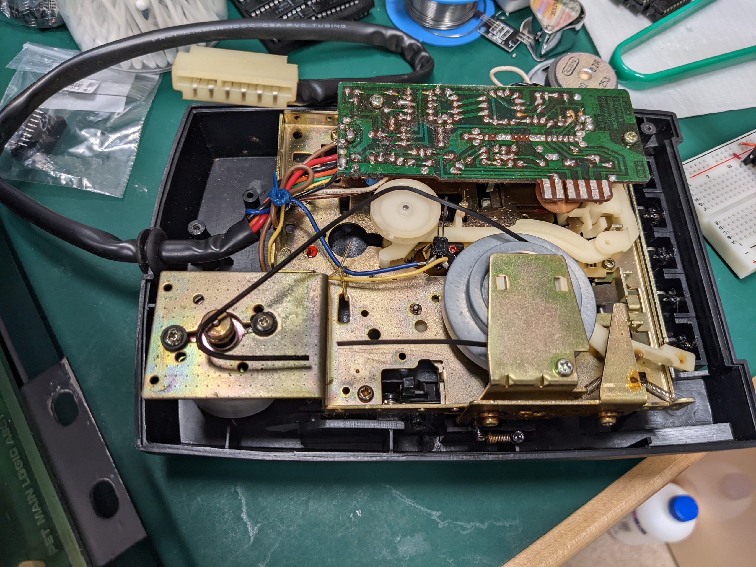
On the PET’s internal drive I had to replace the drive belt, which had snapped. Here’s someone who created replacement belts using their 3d printer: https://www.insentricity.com/a.cl/275/making-belts-with-a-3d-printer / https://www.thingiverse.com/thing:2600198/files Armed with this person’s measurements, I chose a pack of replacement drive belts from Amazon that seemed like they should have fitting ones (they did, though the belts were a bit thinner than advertised): https://www.amazon.co.jp/gp/product/B08JP7J5VX/. Cleaning the heads and the capstan and pinch roller (https://en.wikipedia.org/wiki/Tape_transport) with IPA made things work.
Running some software
With a Datasette drive (for use with C64s and similar machines), it’s very easy to take off the cover (just lift it a bit further from it’s open position). With the cover removed, it’s very easy to put software on the PET using a 3.5mm/cassette adapter.
Most software written for the PET doesn’t seem to work on the PET 2001 (even the 8K model), but there are some games on http://www.zimmers.net/anonftp/pub/cbm/pet/games/english/index.html that work. (Search the page for ‘2001’)
There’s one more step however, as these are .prg files. I used wav-prg to convert the .prg files into .wav files. Quick setup:
git clone https://git.code.sf.net/p/wav-prg/libaudiotap
git clone https://git.code.sf.net/p/wav-prg/libtap
git clone https://git.code.sf.net/p/wav-prg/code
cd wav-prg-libtap
make libtapdecoder.so
make libtapencoder.so
cd ../wav-prg-libaudiotap
make clean # may not be necessary but it's in my notes, perhaps for a reason
make -j4 DEBUG=y LINUX64BIT=y libaudiotap.so # DEBUG=y is in my notes, perhaps for a reason
cd ../wav-prg-code
make clean
make -j4 cmdline/wav2prg DEBUG=y AUDIOTAP_HDR=../wav-prg-libaudiotap/ AUDIOTAP_LIB=../wav-prg-libaudiotap/
make -j4 cmdline/prg2wav DEBUG=y AUDIOTAP_HDR=../wav-prg-libaudiotap/ AUDIOTAP_LIB=../wav-prg-libaudiotap/

# for PET: (-s seems to be required)
LD_LIBRARY_PATH=../wav-prg-libaudiotap/:../wav-prg-libtap/ cmdline/prg2wav -s -w space\ invader.wav space\ invader.prg
I don’t remember why, but I’d enabled debugging in my Makefiles as follows. It’s unlikely that these changes are needed.
wav-prg-libaudiotap:
diff --git a/Makefile b/Makefile
index 61b0bac..7f3e573 100644
--- a/Makefile
+++ b/Makefile
@@ -14,7 +14,7 @@ libaudiotap.so: libaudiotap.o libaudiotap_external_symbols.o pthread_wait_event.
        $(CC) -shared -o $@ $^ -ldl $(LDFLAGS)

 ifdef DEBUG
- CFLAGS+=-g
+ CFLAGS+=-g -O0
 endif

 ifdef OPTIMISE
wav-prg-code:
diff --git a/Makefile b/Makefile
index f96b135..2442e6c 100644
--- a/Makefile
+++ b/Makefile
@@ -66,7 +66,7 @@ ifdef AUDIOTAP_HDR
   CFLAGS+=-I"$(AUDIOTAP_HDR)"
 endif
 ifdef DEBUG
-  CFLAGS+=-g
+  CFLAGS+=-g3 -O0
 endif

 LDLIBS=-laudiotap
Once you have .wav files, you can just use a cassette tape adapter for car stereos as described above. Unfortunately the edge connector for the PET’s second datasette drive doesn’t have enough clearance, so I disconnected the internal drive and once again connected the Datasette drive instead. Then you just type “load” and enter and press play, then you play back the .wav file from your computer.
Here’s the title screen of a random game that I found that just so happened to almost work on the PET 2001 with some minor bugs (perhaps it was developed with a different machine in mind), Diamond Hunt II: