Adapting vgmplay-msx to work from a MSX1 cartridge without MSX-DOS

Summary

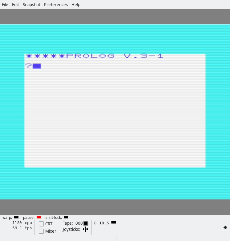
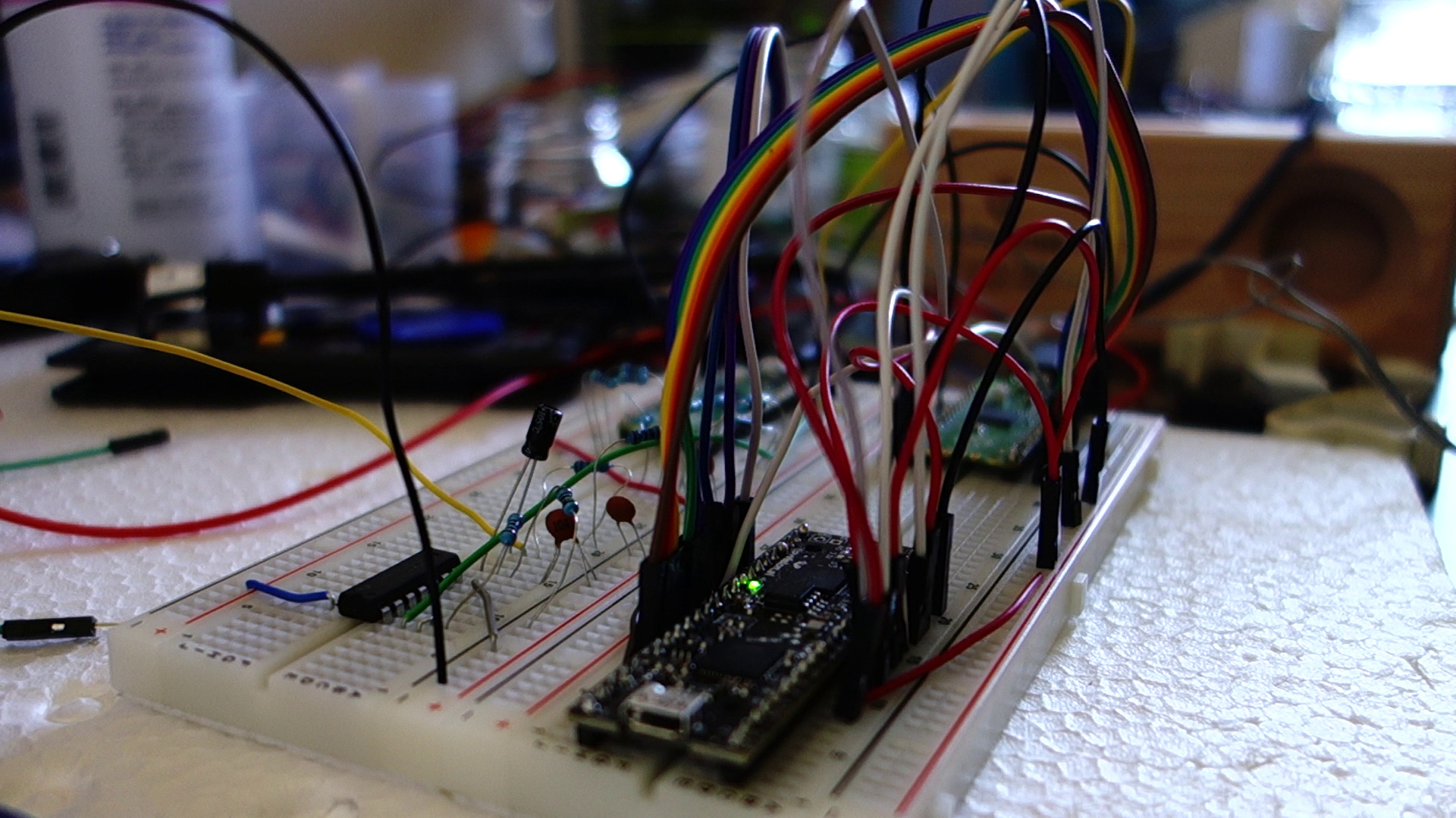
I have a Yamaha MSX1 (YS-503) with 64 32 KB of RAM and an SFG-01, which has a YM2151 on it. I do not have a floppy drive, but I have a way to easily “make cartridges” that are up to 48 KB in size. This blog post explores the source code of vgmplay-msx and ports portions of the program to work off a cartridge. Here’s how the result looks in openMSX:

Here are ROM files that work in OpenMSX, one with the SFG-01 inserted into slot 2, and the other with the SFG-01 inserted into slot 3, both playing the first ~20 seconds of track 2 on https://vgmrips.net/packs/pack/fantasy-zone-ii-dx-sega-system-16c, “10 Years After ~ Cama-Ternya [Demo]”.

vgmplay-msx deep dive

VGM files have a 128 or 256-byte header followed by the actual song data. The song data entirely consists of 1-byte commands possibly followed by a couple bytes of arguments to the command. The only commands we are interested in are “YM2151 register write” and the “wait” commands, of which there are a few. (And maybe the end of song/loop commands.) Everything else is irrelevant for our setup and what we want to do.

We only have 48 KB of ROM space, which means that it’s a bit of a tight fit for the program and the song data. The stock vgmplay.com file is about 32 KB, but it includes code (src/drivers/) for a lot of chips. We only need src/drivers/SFG.asm. There are also vast regions of 0s. We also don’t need any code to make song data fit into more than 64 KB of RAM (src/MappedReader.asm). We don’t need support for compressed .vgm files. And we don’t need any MSX-DOS-specific code, nor do we need code to handle reading from the floppy drive. Song data tends to be relatively large too: the song I used in Raspberry Pi Pico implementation of the YM3012 DAC (mono) was around 1 minute and is 68 KB in size. We’ll have to either truncate it, or find something shorter or simpler.

vgmplay-msx is written in a rather unusual assembly dialect. The assembler supports scoping, and there appears to be a bit of a “class” hierarchy. For example, MappedReader (src/MappedReader.asm) extends Reader (lib/neonlib/src/Reader.asm).

After putting the MSXDOS22.ROM into .openMSX/share/systemroms and booting from MSXDOS22.dsk, and adding the Yamaha SFG-01 extension (Hardware -> Extensions), and executing ‘make’ in the vgmplay-msx source directory, I was able to execute ‘vgmplay foo.vgm’ in MSX-DOS and hear the VGM file being played back in openMSX. After reading the code for a little bit, I opened and connected the debugger. In System -> Symbol manager, we can read the symbols generated by the assembler, vgmplay.sym, which are quite convenient.

Note: openMSX debugger fails to show the correct disassembly when there is a label in the middle of an instruction. Below, 427F 26 db #26 and 4280 79 ld a,c are actually a single instruction, which you can manually decode using something like this:

$ echo -n -e '\x26\x79' > foobar
$ z80dasm foobar
; z80dasm 1.1.5
; command line: z80dasm foobar
        org     00100h
        ld h,079h
Here, in Reader_Read_IY we read a byte from the VGM music data. We then create an address by reading one byte from 79xx (where xx is the read byte) and one byte from 80xx (again, xx is the previously read byte) and jump to it. This is the main jump table.

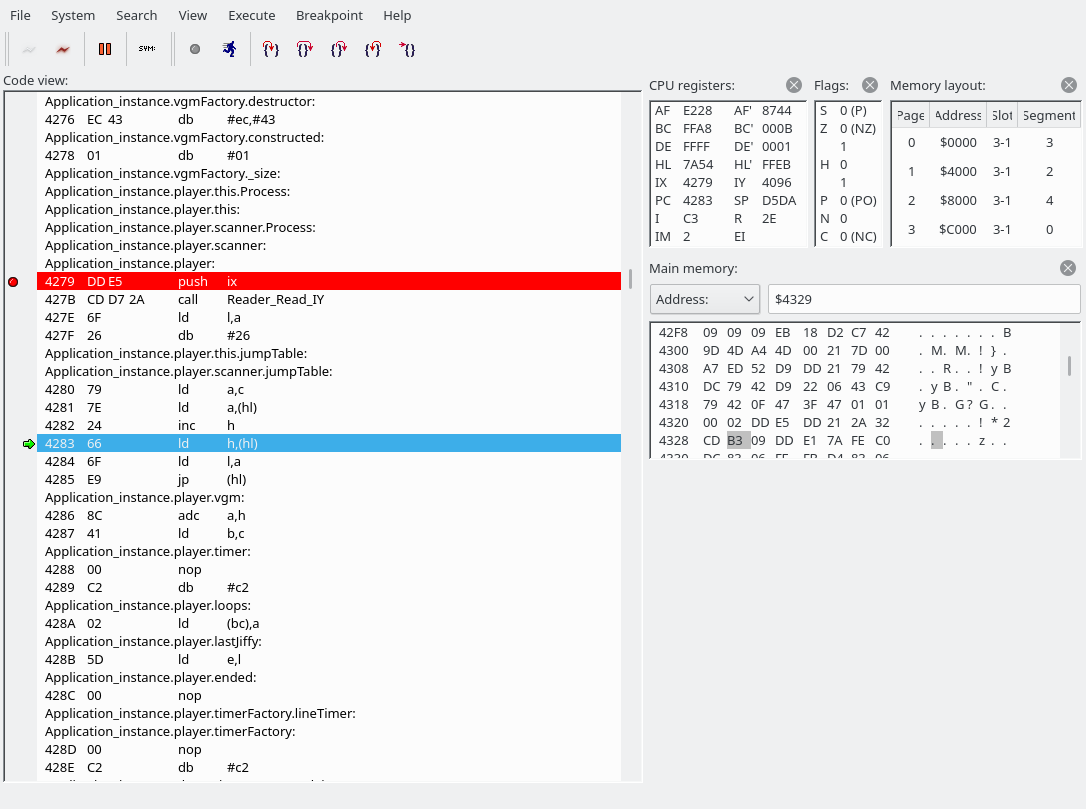
The jump table is defined in src/Player.asm, and for efficiency reasons is separated into two in Player_InitCommandsJumpTable in the same file.

; Shuffles the commands jump table so that the LSB and MSB are separated.
; This allows faster table value lookups.
Player_InitCommandsJumpTable: PROC
...

The byte we read was a 0x54, which indicates that we are going to write to the YM2151. This is where we have jumped:

We are going to read a word (two bytes). The first byte holds the address of the YM2151 register to write to, the second byte the data. It looks like the next instruction has been butchered by the openMSX debugger again. C3F069 is actually “JP 69F0”.
Reader_ReadWord_IY simply calls Reader_Read_IY twice. (The first screenshot also used Reader_Read_IY to fetch the command byte.) The address goes into the E register, the data into the D register.

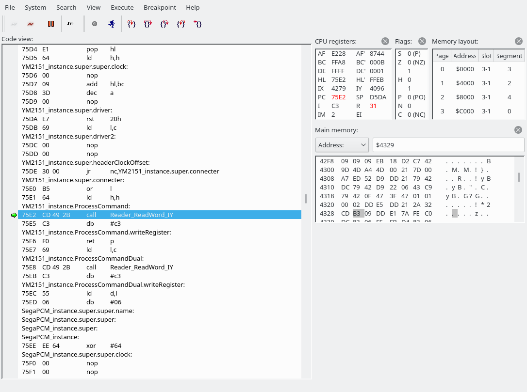
We have now jumped to 69F0. The source file is src/drivers/SFG.asm.

There are a few things to unpack here.

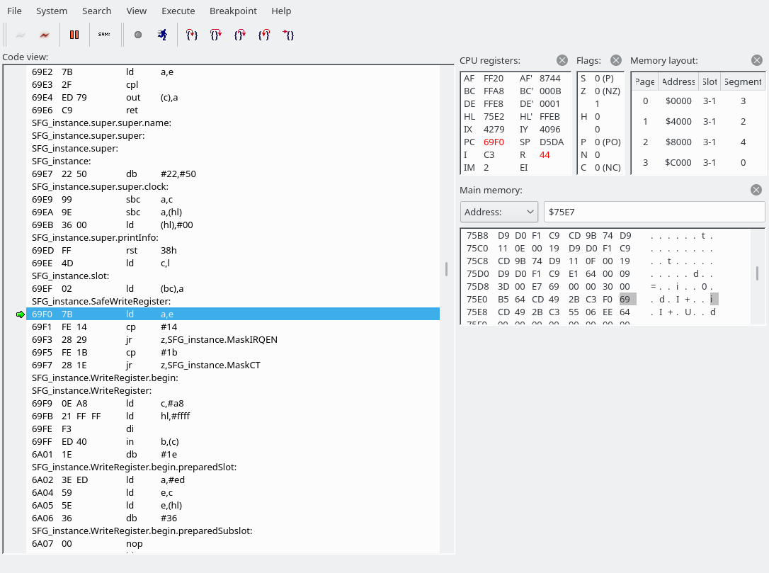
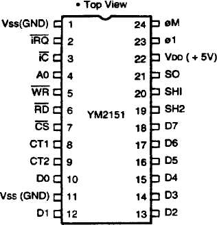
First of all, we look into the address value and may jump to MaskIRQEN or MaskCT if the address is exactly 0x14 or 0x1b, respectively. Our E is set to E8, so that doesn’t apply here, so we fall right through into SFG_instance.WriteRegister. I am going to guess that the MaskIRQEN and MaskCT sections modify some bits in the address register to perhaps turn off a feature in the YM2151 that would trigger output on the interrupt or one of the CT pins, but I don’t know for sure. Here’s a pinout of the YM2151 BTW:

There are IRQ and CT pins, and IIRC they are output pins.

Next, let’s edit the symbol file to work around the debugger’s inability to disassemble instructions that have labels in the middle… Search for ‘6a02’ and ‘6a07’ in the symbol file, remove the symbol file from the debugger, and add it back in again. Then our WriteRegister function becomes a little clearer:

We read from and write to the A8 I/O port. This screenshot is from after executing the OUT instruction, which modifies the slot selection; the modifed slots are highlighted in red in the upper-right corner.

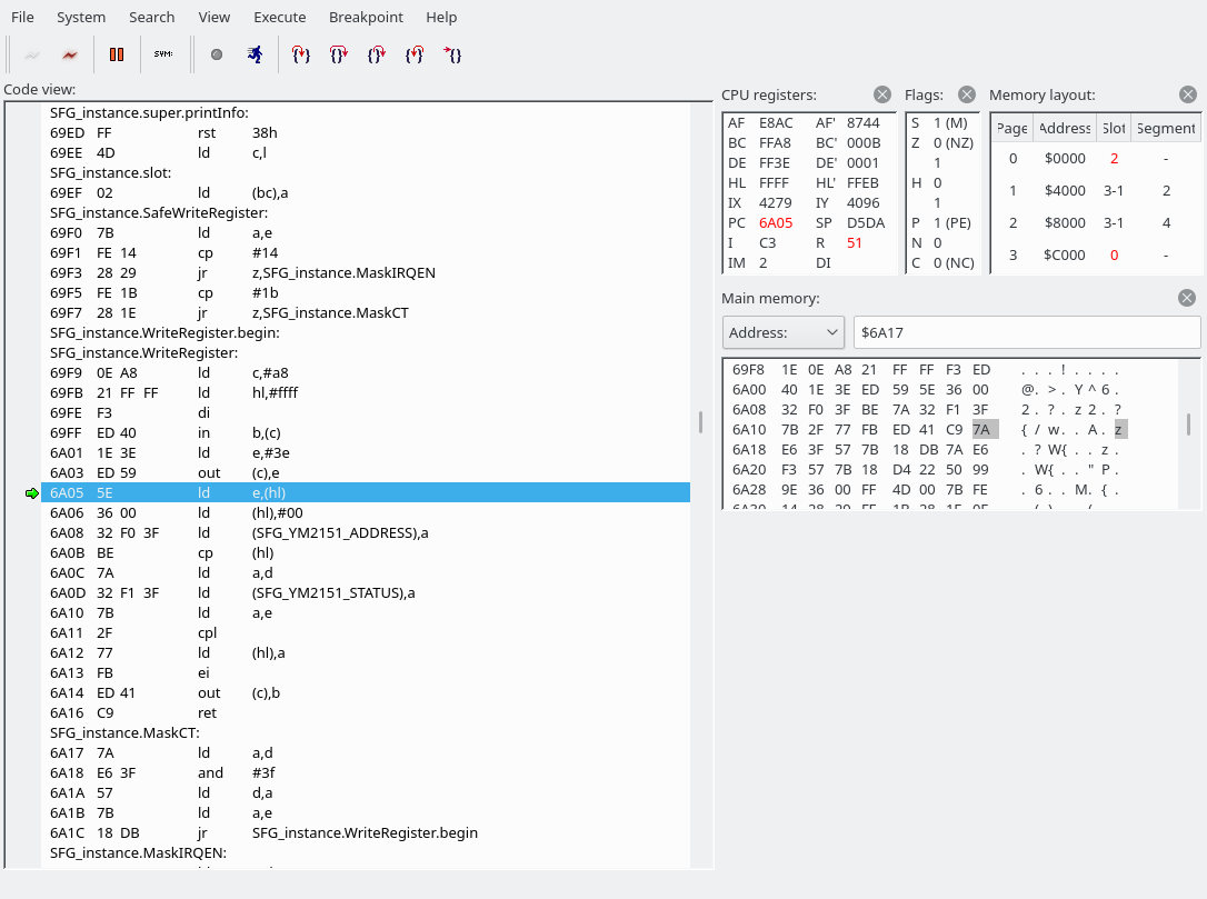
The SFG’s YM2151 registers are memory-mapped(!) at the following addresses:

SFG_YM2151_STATUS: equ 3FF1H
SFG_YM2151_ADDRESS: equ 3FF0H
SFG_YM2151_DATA: equ 3FF1H
SFG_ID_ADDRESS: equ 80H
SFG_CLOCK: equ 3579545

If you know quite a bit about how the MSX works, you may know that the MSX in general doesn’t use memory-mapped I/O, and you may also know that 0000-3FFF is where the system ROM is usually located (mapped; it can be unmapped and something else can be mapped instead). In the screenshot above, you can see that there’s an “in b,(c)” instruction at 69FF, where C holds #A8. This is the I/O register that allows you to remap stuff. See this link if you want to know more about how this register works: http://map.grauw.nl/resources/msx_io_ports.php#ppi. (BTW, this page is probably authored by the same person who wrote vgmplay-msx.) So “in b,(c)” saves the contents of the #A8 into B.

In order to perform memory-mapped I/O, we have to unmap any ROM or RAM currently mapped in. And when we’re done, we obviously have to map it back in. (Oh, good that we saved the #A8 contents into B.) ROM and RAM mappings vary between MSX models, which means the OUT part of the code is probably generated dynamically somewhere in the init code. (Hence the labels in the middle of our instructions.) The next instructions (6A05 and 6A06) save the contents of the subslot register (FFFF) into E (so we can change it back later) and set the subslot register to 0. (Note that at this point our register address has already been moved into register A, while data is still in register D.)

After the OUT is done, we just write our address to SFG_YM2151_ADDRESS and our data to SFG_YM2151_STATUS (which is an alias of SFG_YM2151_DATA, the address is 100% the same). The “cp (hl)” instruction in the middle is just to wait a short moment according to the comment in the source code: “; R800 wait: ~4 bus cycles”. When we’re done, we set the slot and subslot registers back to what they were.

So that’s how we perform a register write. We also need to know how to wait a specific number of cycles. VGM files are full of wait commands, and if the amount of waiting we do is too imprecise, that will definitely be audible. The wait commands in VGM files assume an output sample rate of 44100 Hz, which is different from the actual sample rate on real hardware. The number specifies the number of samples to just leave the YM2151 alone to do its thing. In reality, the YM2151 in the SFG-01 outputs at 3579545/2/32 = 55930.390… Hz. The Z80 runs at 3579545 Hz. So we get 64 Z80 cycles per sample, but because the VGM file wait cycles assume a different sample rate, just adding NOPs would end up being rather imprecise. What’s more, some VGMs are for machines where the YM2151 is clocked at 4000000 Hz, which results in an output rate of 4000000/2/32 = 62500 Hz.

So let’s… jump back to our jump table to see what happens when a wait instruction is encountered!

	dw Player_WaitNSamples        ; 61H
	dw Player_Wait735Samples      ; 62H
	dw Player_Wait882Samples      ; 63H
...
	dw Player_Wait1Samples        ; 70H
	dw Player_Wait2Samples        ; 71H
	dw Player_Wait3Samples        ; 72H
	dw Player_Wait4Samples        ; 73H
	dw Player_Wait5Samples        ; 74H
	dw Player_Wait6Samples        ; 75H
	dw Player_Wait7Samples        ; 76H
	dw Player_Wait8Samples        ; 77H
	dw Player_Wait9Samples        ; 78H
	dw Player_Wait10Samples       ; 79H
	dw Player_Wait11Samples       ; 7AH
	dw Player_Wait12Samples       ; 7BH
	dw Player_Wait13Samples       ; 7CH
	dw Player_Wait14Samples       ; 7DH
	dw Player_Wait15Samples       ; 7EH
	dw Player_Wait16Samples       ; 7FH
	dw Player_Skip1               ; 80H
	dw Player_Wait1Samples        ; 81H
	dw Player_Wait2Samples        ; 82H
	dw Player_Wait3Samples        ; 83H
	dw Player_Wait4Samples        ; 84H
	dw Player_Wait5Samples        ; 85H
	dw Player_Wait6Samples        ; 86H
	dw Player_Wait7Samples        ; 87H
	dw Player_Wait8Samples        ; 88H
	dw Player_Wait9Samples        ; 89H
	dw Player_Wait10Samples       ; 8AH
	dw Player_Wait11Samples       ; 8BH
	dw Player_Wait12Samples       ; 8CH
	dw Player_Wait13Samples       ; 8DH
	dw Player_Wait14Samples       ; 8EH
	dw Player_Wait15Samples       ; 8FH

As we can see, there are a lot of commands that perform waits. For Player_Wait1Samples, we jump to 492F:

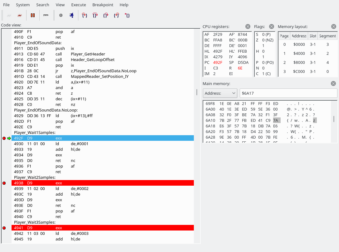
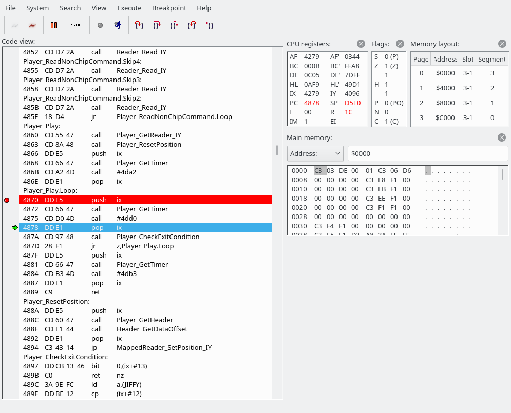
The “exx” instruction switches between the directly usable registers and the shadow registers. (“EXX exchanges BC, DE, and HL with shadow registers BC’, DE’, and HL’.”) Wow, the Z80 has so many registers. All we do here is add 1 to hl’. In a special case, we pop AF from the stack, but we have no choice but to ignore that for now. And basically, Player_Wait2Samples, Player_Wait3Samples, …, Player_Wait16Samples, Player_Wait735Samples, Player_Wait882Samples, all work the same. Player_WaitNSamples grabs its argument, and apart from that also works the same as the others. Here’s a screenshot of the stack, and it’s always the same for all Player_Wait* sections:

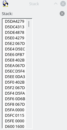
That is, we are going to jump back to 4279, and we have already seen the code at 4279. Scroll up to see it again. It’s our main loop body, where we grab a command and use the jump table to jump somewhere. (What I hadn’t noticed or mentioned above was that it begins with a “push ix” command, which seemingly puts 4279 back on the top of the stack each time.)

Well, this is a good time to think about that “ret nc pop af ret” bit again, right? If the carry flag is set, we do not return. Instead, we grab 4279 off the stack and shove it into the AF register. Then we return, and this time we should return to 4313, according to the above stack screenshot. The carry flag is set if shadow HL overflows. Currently, it’s FF71. Hmm, just a few F9 presses maybe.

Intermission, sort of

But let’s take a step back and think about what we have seen so far. Perhaps the MSX is just way too slow to play VGMs in real time with perfect timing, and it just makes sense to skip all wait commands and just sync whenever the carry flag is set?

There’s a lot of timing code, and it’s all a bit complicated because the code seems very un-assembly-like. (But as this piece of software supports many different configurations, the somewhat object-oriented patterns may maybe make sense.) Looking back at the projects homepage, it appears that on the MSX2, the timing is 300 Hz, so perhaps that means the waits are ignored as they are encountered, but everything is put in sync (up to?) 300 times a second. It looks like on the MSX1 the timing is either 50 or 60 Hz.

The timing resolution is 50 or 60 Hz on MSX1 machines with a TMS9918 VDP, 300 Hz on machines with a V9938 or V9958 VDP, 1130 Hz if a MoonSound or OPL3 is present, and 4000 Hz on MSX turboR.

https://www.grauw.nl/projects/vgmplay-msx/

While the site says that vgmplay-msx works on MSX1 machines, I’m not entirely sure what kind of hardware configuration in e.g. openMSX would allow us to do that, because vgmplay-msx needs 128 KB of RAM, and MSX-DOS2. As far as I know you also can’t give an existing MSX2 machine an MSX1-class TMS9928A VDP, because the MSX2 logo requires the V9938. (Maybe you could try to give it an MSX1 BIOS too, but I think I’m outta here.)

(End of intermission)

So what we’re going to do is: recompile without LineTimer support by commenting out in src/timers/TimerFactory.asm:

TimerFactory_Create:
; 	call TimerFactory_CreateTurboRTimer ; this line and
; 	call nc,TimerFactory_CreateOPLTimer ; this line and
; 	call nc,TimerFactory_CreateLineTimer ; this line.
	call nc,TimerFactory_CreateVBlankTimer ; this line is left as-is
	ret

So anyway, we’re now running using the VBlankTimer and added breaks like this:

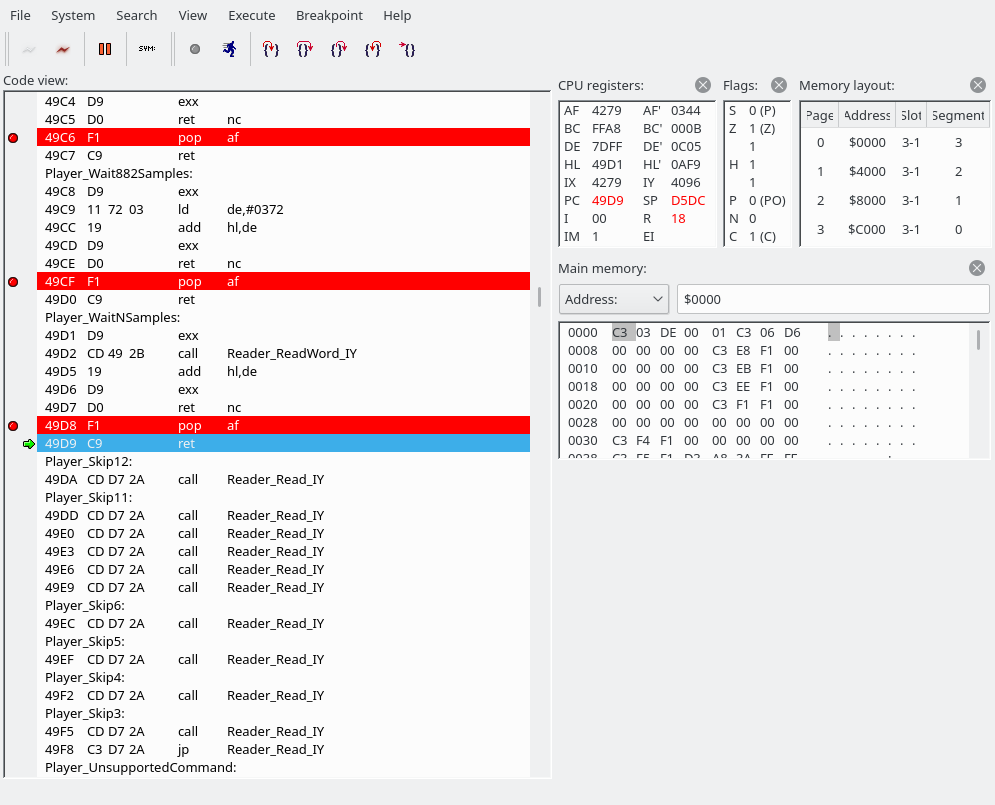
And after the ret we end up here:

Note that Application_instance.player.time is a variable, not something disassemblablablable.

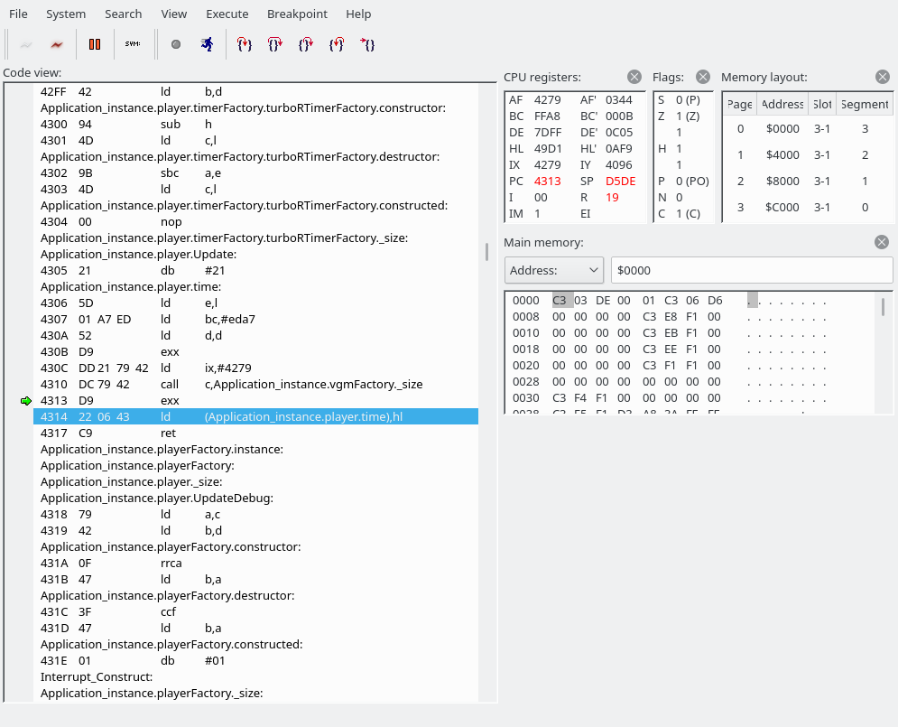
So what we do here: we save our shadow HL (which has gone past FFFF; it’s currently 0AF9) to a variable called Application_instance.player.time. And after the next ret we’re here:

At some point, we get to “Application_instance.player.timerFactory.vBlankTimer.Update”. Wait, what language is this again?

Over here we loop between 42A1 and 42A5 until the JIFFY value contains something different.

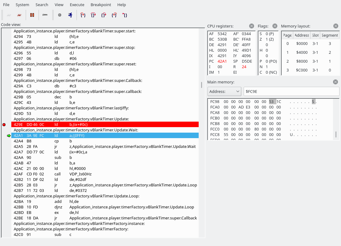
Here’s the code with more symbols:

Update: PROC
	ld b,(ix + VBlankTimer.lastJiffy)
Wait:
	ld a,(JIFFY)
	cp b
	jr z,Wait

Wait, what’s JIFFY? It’s actually a system variable:

Address: FC9Eh
Name: JIFFY
Length: 2

Contains value of the software clock, each interrupt of the VDP it is increased by 1. The contents can be read or changed by the function ‘TIME’ or instruction ‘TIME’

https://www.msx.org/wiki/System_variables_and_work_area

After the tight loop is finished, we update lastJiffy with the new JIFFY. Then we set a value for our shadow HL. We either initialize DE with 0x2DF or 0x372 depending on whether we’re on 60 Hz or 50 Hz. (Update: I don’t think this routine works on the MSX1!) Then, we jump to a callback that was set way back when our Timer was first created (i.e., during program initialization), in src/Player.asm:

Player_Construct:
	ld (ix + Player.vgm),e
	ld (ix + Player.vgm + 1),d
	call Player_SetLoops
	ld hl,Player_commandsJumpTable
	call Scanner_Construct
	push ix
	ld e,ixl
	ld d,ixh
	ld hl,DEBUG ? Player.UpdateDebug : Player.Update
	add hl,de
	call Player_GetTimerFactory
	call TimerFactory_Create
	call nc,System_ThrowException
	ld e,ixl
	ld d,ixh
	pop ix
	ld (ix + Player.timer),e
	ld (ix + Player.timer + 1),d
	jr Player_ConnectPCMWrite

Actually executing the code we see that we end up in Application_instance.player.Update:

Application_instance.player.time causes the disassembly to look wonky. 4305-4307 loads Application_instance.player.time, currently set to 0292, into the HL register. The next valid instruction is 4308. Also, Application_instance.vgmFactory._size is an alias of Scanner.Process (which is the code we have seen a number of times, where we grab a byte and use the jump table)

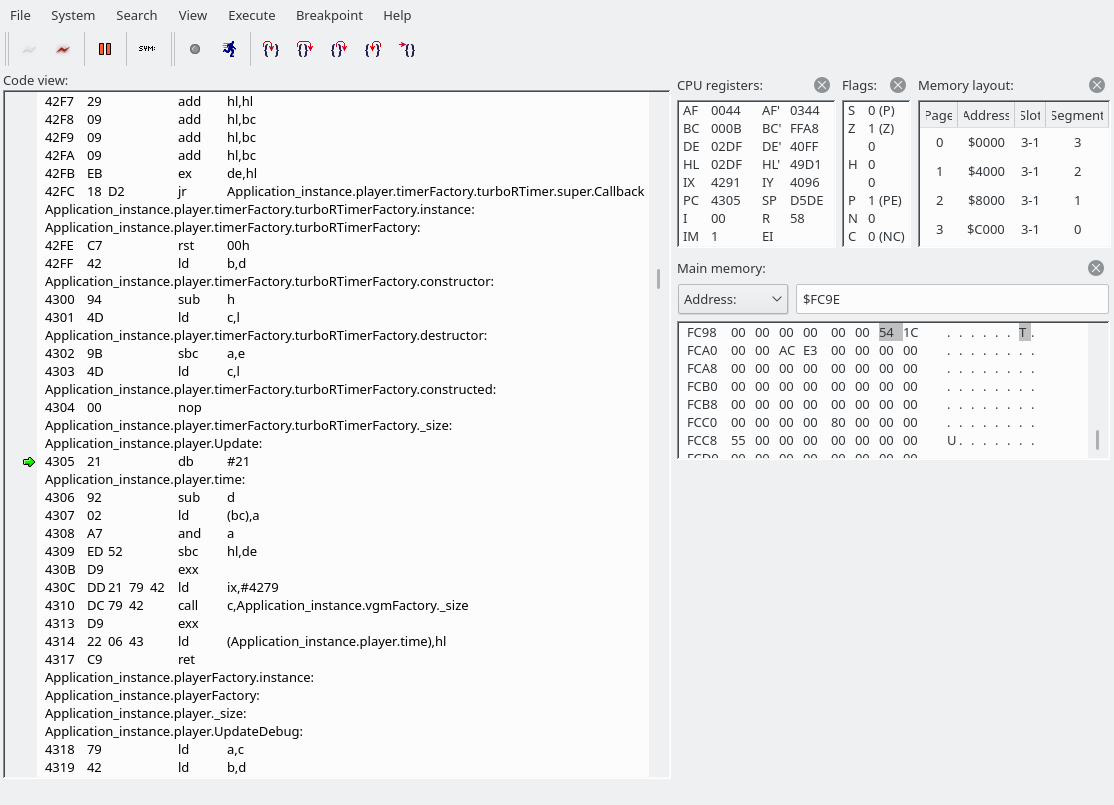
We are about to do “sbc hl,de”. The HL register has 0292, DE contains 02DF or 0372, depending on whether the system is 60 Hz or 50 Hz. Note: I don’t think the routine to figure out whether the system is 50 or 60 Hz works on MSX1s.

Address: FFE8h
Name: RG09SAV
Length: 1

System saves the byte written to the register R#09 here, Used by VDP(10). (MSX2~)

https://www.msx.org/wiki/System_variables_and_work_area#VDP_Registers

Anyway, I don’t really know where the carry flag that SBC is supposed to take into account comes into play (it’s not set in the code visible in the above screenshot). But anyway, 0292 – 02DF = FFB3. And this is the value we will add numbers to again in the Wait* procedures. Or let’s use our brains just one more time:

  • There are 0x02DF samples per 60 Hz VSYNC (or 0x0372 samples per 50 Hz VSYNC)
  • We already “overshot” our previous target by 0x0292 samples in the previous run
  • We have 0x02DF-0x0292=0x4D samples left until we should wait for VSYNC again
    • Note: 0x10000-0xFFB3=0x4D

We have now seen enough to take just the parts we need.

What parts do we need?

  • Jump table
    • We’ll edit it to remove support for anything but the YM2151 though
    • We’ll also need the remaining jump locations of course (loop, end of song, wait, etc.)
    • (Also code to make jump table more efficient)
  • SFG register writing code
    • (If possible, also init code to figure out correct slot selection register values.)
  • Timing code
    • VSYNC-based timer only
  • The song data will be directly on the cartridge, so

Let’s do it

For convenience/compatibility with the existing code we will be using the same assembler, Glass, though I don’t think we’ll be using any of its unique features. We won’t be using constructors or a heap, even, but we will use the stack in the same way the existing code is using it.

Cartridge contents are mapped to 4000-7FFF, or if no cartridge was detected at 4000-, then 8000-BFFF. (The MSX BIOS maps in the candidate addresses (starting with 4000-7FFF) and checks for the presence of a header at the beginning of this address space to see check if a cartridge is inserted.) Thus, programs must start like this (I added some useless code in the entry_point that makes it easier to test that this thing is working):

org 4000h ; hex number syntax may differ from assembler to assembler
db "AB" ; all cartridges have this
dw entry_point ; 16-bit absolute pointer
db 00,00,00,00,00,00 ; can be anything probably

entry_point:
    nop
    jp entry_point

Compilation example if saved as foo.asm:

$ z80asm -o foo.rom foo.asm
$ dd if=/dev/zero of=foo.rom bs=16384 seek=1 count=0 # actually creates a sparse file but that's fine for all intents and purposes
$ hexdump -C foo.rom 
00000000  41 42 aa 0f 00 00 00 00  00 00 00 18 fd 00 00 00  |AB..............|
00000010  00 00 00 00 00 00 00 00  00 00 00 00 00 00 00 00  |................|
*
00001000
The disassembler is (rightly) confused again at 3FFF, but we can see our code and we are indeed executing a NOP and then jumping right back to that NOP, ad infinitum.

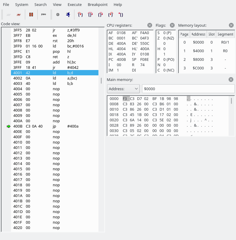
However, we only got our cartridge mapped up to 7FFF, but if we want its whole 48 KB mapped, we need to set port #A8. #A8 of course holds an 8-bit number, but you should interpret it as four 2-bit numbers. “00 00 00 00” (0x00) would mean that everything is on slot 0. “01 01 01 01” (0x55) would mean that everything is on slot 1. You can choose any combination your hardware likes.

All MSXs have Main-ROM in primary slot 0 or in secondary slot 0-0 (see variable EXPTBL below for more details). Cartridge slot that is on top of computer is typically slot 1. If there is another expansion port then this is often slot 2. Although the internal RAM should preferably be in slot 3, this is often not the case for MSX1s.

https://www.msx.org/wiki/Slots

The cartridge slot is “typically slot 1”. I don’t know if there are any computers that have a different number, but it’s easy to determine the number in software: we’re running off 4000-7FFF, so the slot is already set correctly here. We just need to set the page we want to the same number.

Now, if we want to set 4000-FFFF to the cartridge, we won’t have any RAM. And therefore, no stack. vgmplay uses the stack (as seen earlier). vgmplay also uses the BIOS (mapped into 0000-3FFF) because we need the VSYNC interrupt handler, and this interrupt handler writes to a system variable called JIFFY, which is located at FC9E, as mentioned above. We could decide to leave the last slot for RAM, limiting the amount of song data we can play to less than 32 KB. But the amount of RAM we need isn’t exactly very much. In addition, as we have seen, some parts of the vgmplay code are self-modifying.

So what we’ll do instead is: copy the entire cartridge to RAM. Then we’ll be able to use self-modifying code, and we’ll be able to have a stack too. Sounds easy? Well, let’s say we have our copying routine at ROM address 4100. What happens if we try to copy the ROM at 4000-7FFF to RAM? We’ll execute instructions at 4100, and these instructions say to switch 4000-7FFF to RAM, which we do, and then what? We’ll have pulled the carpet from under our feet! One way to avoid this problem is by having two (or more) copies of the copying code.

So first we could copy 8000-BFFF to RAM, which doesn’t require any precautions. For the page starting at C000, we probably shouldn’t copy past F000, which is where the stack and some system variables appear to be located. (Not that the stack holds anything.) But otherwise no precautions are required. Then, we jump to (e.g.) 8100, where we have another copy of our copy routine, and copy 4000-7FFF. (We’ll choose a different location for the second copy because we’d expect the song data to start before 8100. Perhaps F200 or so.) If we copy byte-by-byte (or word-by-word), switching between ROM and RAM every time, we can use a single register to hold the read value and won’t need any buffer memory (which would complicate things a bit). (It finishes in less than 1 second per 16 KB, so no issues here as this is init code.)

One more annoyance is that since we do not have a stack, it doesn’t make a lot of sense to ‘call’ the copy code. Jumping to the code isn’t exactly fun either because we’d have to know where to jump back, and the register dance becomes a little annoying. So we’ll just copy and paste the code. Here’s the first-draft code to copy 4000-F000 from ROM to RAM. This code assumes that the BIOS ROM is in slot 0, the cartridge ROM in slot 1, all RAM in slot 3, and that there are no subslots. This assumption doesn’t hold on many systems. This code can be compiled using z80asm using the following command line:

z80asm -o foo.rom foo.asm
org 4000h
db "AB"
dw entry_point
db 00,00,00,00,00,00

entry_point:
    ld a,01010100b ; set rom - cart - cart - cart
    out (0a8h),a

    ; copy 8000-bfff
    copy_8000_bfff:
    ld hl,08000h ; start at 8000
copy_8000_bfff_loop:
    ld a,(hl) ; read from ROM address (hl)
    ld d,a
    in a,(0a8h)
    ld b,a ; store original value
    or 000110000b ; set bits 5-4 to 11 (RAM) (actual value depends on machine)
    out (0a8h),a ; set port
    ld (hl),d ; store value read from ROM address (hl) to RAM address (also hl of course)
    ld a,b ; load a with original value
    out (0a8h),a ; set port back
    inc hl
    ld a,h
    cp 0c0h
    jp z,copy_c000_f000 ; done with this copy
    jp copy_8000_bfff_loop
    
copy_c000_f000:
    ld hl,0c000h ; start at c000
copy_c000_f000_loop:
    ld a,(hl) ; read from ROM address (hl)
    ld d,a
    in a,(0a8h)
    ld b,a ; store original value
    or 011000000b ; set bits 5-4 to 11 (RAM) (actual value depends on machine)
    out (0a8h),a ; set port
    ld (hl),d ; store value read from ROM address (hl) to RAM address (also hl of course)
    ld a,b ; load a with original value
    out (0a8h),a ; set port back
    inc hl
    ld a,h
    cp 0f0h
    jp z,copy_4000_7fff ; done with this copy
    jp copy_c000_f000_loop

done_copying:
    ld a,011111100b ; switch to 4000-ffff to RAM
    out (0a8h),a
nop:
    nop
    jr nop ; infinite loop

seek 0b000h ; b000+4000 = f000
org 0f000h

copy_4000_7fff:
    ld hl,04000h ; start at c000
copy_4000_7fff_loop:
    ld a,(hl) ; read from ROM address (hl)
    ld d,a
    in a,(0a8h)
    ld b,a ; store original value
    or 000001100b ; set bits 5-4 to 11 (RAM) (actual value depends on machine)
    out (0a8h),a ; set port
    ld (hl),d ; store value read from ROM address (hl) to RAM address (also hl of course)
    ld a,b ; load a with original value
    out (0a8h),a ; set port back
    inc hl
    ld a,h
    cp 080h
    jp z,done_copying ; done with this copy
    jp copy_4000_7fff_loop

This is pretty almost all that we need to code ourselves, everything else will be copy and pasted from vgmplay-msx! Note: the above doesn’t actually assemble in Glass because Glass requires that reserved words like “org” are indented, and “seek” isn’t supported. The final code will therefore look a bit different.

Putting all the necessary bits together (and throwing out everything else)

I got it to work on an emulated version of my Hitachi H2. (My apologies to the original author of vgmplay. I completely butchered their code.) And right when I start looking at the slot map of the computer I actually intended to run this one (Yamaha YIS-503), I noticed that the silly machine only has 32 KB of RAM, har har har. And (this was expected though not quite to this extent) the slot map is different, so the #a8 port settings will have to adjusted. With 64 KB we could load the whole 48 KB ROM into RAM, but with 32 KB, arranged the way it is, we’ll boot from 8000 and ignore 4000-7FFF. (We could rewrite the self-modifying code to refer to variables in RAM space instead, but unfortunately I’m running out of steam on this project. I’d planned two days and it’s about three days already! :p)

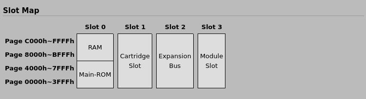
It ended up working on this machine too, of course. Except, I think that openMSX might be putting the SFG-01 into a different slot (2), rather than slot 3 as sort of indicated in the above screenshot. Due to the limited amount of RAM, our music gets truncated even earlier than before. Feel free @ anyone wanting to fix this. TBH, I just want to be able to hear if the music sounds okay or not. (Edit 2023/04/08: I checked on a real YIS-503 and the SFG-01 was indeed in slot 3, so the above screenshot is correct.)

Code is at https://github.com/qiqitori/vgmplay-msx-cartridge.

AI day in retroland. Prolog on the Commodore VIC-20! (Needs expanded RAM)

Today’s post is AI-heavy! AI as in OCR (“optical character recognition”). We will OCR (“optical character recognize”) a hex listing for a Prolog interpreter (which used to be thought of as an “AI language”) for the Commodore VIC-20! (As a bonus, some small parts of the tools I made to verify the OCR transcription were written by ChatGPT.)

As you may have heard before, OCRing stuff is error-prone. Ls and Is and 1s being mixed up makes natural language texts annoying to read, and program listings almost useless, because you’ll spend a long time trying to find the error. Why does this take a long time? Because our eyes (and attached circuitry) don’t notice tiny imperfections in a sea of details. However, we are quite good at noticing things that look completely different from the surrounds.

With hex OCR, we really only have to worry about 16 different classes (types of digit). This makes it relatively easy to verify if our OCR is correct (and perform fixes), because we can take our OCR’d digits and temporarily (while remembering their original position) display them all, sorted by class. Like this:

We can easily see that all these are indeed 3s, 4s, and 5s.

Or like this:

We can easily see that there’s a 0 in our list of 6s and a 9 in our list of 7s.

(Note: occasionally, OCR tools will turn a single character into two characters, or the other way round. That kind of problem will require manual edits.)

I created two tools, a segmentation tool, and the above verification tool, and described them a little more in this post: OCRing hex dumps (or other monospace text) and verifying the result. The tools themselves are at https://blog.qiqitori.com/ocr/monospace_segmentation_tool/ and https://blog.qiqitori.com/ocr/verification_tool/.

This is the scan in question: https://archive.org/details/Io19833/page/n342/mode/1up. Here’s the rather good-looking first page:

I/O アイ・オー 1983年3月号

For the original OCR, I used a program called ProgramListOCR. The program supports OCRing hex dumps. This program requires that you touch up input images in (e.g.) Gimp before loading them. It’s not difficult, and the program’s README describes what needs to be done. Unfortunately, this process removes a small amount of detail from the image, making it harder to distinguish between, e.g., Bs and 8s. And unfortunately, I believe the program only runs in Windows. Here’s a screenshot of the program running:

ProgramListOCR made 142 digit mistakes. The hex dump consisted of 7310 digits, so the overall error rate is 1.943%, or the accuracy is 98.057%.

How to download and run Prolog

In order to run this on your VIC-20 emulator, you need to set it to have an 8K memory expansion. Then you need to load the binary data into RAM; starting address is 2204. In VICE, you can add the memory expansion in this config window:

Select at least “Block 1 (8KiB at $2000-$3FFF)”. PAL/NTSC etc. do not matter.

To load the binary data into address $2204 and beyond, start the monitor (Alt+H), and then I wish it’d work with ‘load “/path/to/prolog.bin” 0 2204’. But for some reason that doesn’t work; the first few bytes are garbled and the reset isn’t aligned correctly. If you have this issue, try the other file and ‘load “/path/to/prolog_prefixed_with_zeros.bin” 0 2202’. Execute “m 2200” in the monitor to see if VICE loaded your file into the correct address. The following is an example of a successful load:

2200-2203 don’t matter, 2204- should be 78 a9 00 8d, etc.

Then you close the monitor and type “SYS 11445” in the BASIC prompt, and you should get something like this:

Having fun with Prolog

There are various sample programs in the magazine. Note that the Prolog interpreter sometimes gives you a question mark prompt, and sometimes a hyphen prompt. You have to delete these manually by pressing backspace (Delete), depending on what you want to do! Let’s start with this short program:

m(*a.*x)*a*x
m(*b.*x)*a(*b.*y)
-m*x*a*y
p()()
p*x(*a.*y)
-m*x*a*z
-p*z*y
-;
?p(1 2 3)*x
-pr*x
-m;
***answer***
(1 2 3)
(1 3 2)
(2 1 3)
(2 3 1)
(3 1 2)
(3 2 1)
!!fail!!

The next program (actually the first in the magazine, and easiest) is a program that tells you whether the density of blocks 1-4 is high or low, or unknown:

That’s the data and the functions, er, I mean predicates.
weight block1 heavy
weight block2 heavy
weight block3 light
weight block4 light
bulk block1 large
bulk block3 large
bulk block2 small
bulk block4 small
density *x high
-weight *x heavy
-bulk *x small
density *x low
-weight *x light
-bulk *x large
density *x ???
-weight *x heavy
-bulk *x large
density *x ???
-weight *x light
-bulk *x small
-;
?

I believe I speak for us all when I say, the syntax looks a bit weird? Anyway, the first few things are the data, er, I means facts. Then you get a function, er, predicate “signature”, and below the predicate signature you get the actual… predicate definition (the lines that start with a hyphen). (Predicates may also be called rules.) Want to finish up the current rules and start a new one with a different signature? Just backspace away the hyphen. When you’re all done, type a semicolon, and you’ll be back at the ‘?’ prompt. Now we can run queries!

In the screenshot, we first ask which blocks have a high density. The answer is BLOCK2!

Then we ask it the density of BLOCK3 and ask it the reason using the PROOF

?DENSITY BLOCK3 *X
-PROOF;

And the answer is:

/DENSITY BLOCK3 LOW ,BECAUSE*** WEIGHT BLOCK3 LIGHT ,& BULK BLOCK3 LARGE:
/Q.E.D.
DENSITY BLOCK3 LOW...IS TRUE:

OCRing hex dumps (or other monospace text) and verifying the result

Summary: Segmentation tool and OCR verification tool. You can use these tools to either verify an existing OCR’d hex dump, or use them to run your own OCR. (Which isn’t hard! You can probably get ChatGPT to produce a probably working Python script using PyTorch to learn the digits, and easily get 97% (or so) accuracy. Maybe something along the lines of, “Write a Python script that uses PyTorch to train recognition of something like MNIST, except there are 16 classes, not 10. The recognition should use convolutional layers. Input images are PNG files. Labels are in a text file.” (I just tried and the result looks plausible.))

Why hex dumps anyway? Because in the 1980s computer magazines sometimes included printed hex dumps of programs. But that’s just how I got motivated to write these tools. More on that in this post.

If you are familiar with basic image recognition concepts, you may know that detecting hand-written digits is generally considered to be a very easy task, the “hello world” of AI image recognition even. (Didn’t know this? Maybe search for “MNIST dataset”)

If recognizing handwritten digits is considered so easy, recognizing printed digits should be even easier, no? The answer is “yes” and “no”, because I left out some information above. The MNIST dataset consists of images that contain exactly one digit. OCR, on the other hand, requires segmentation. In general, recognizing typed letters if you have them in a nicely cropped single image is quite easy. (Except for letters that look very similar or even identical, of course.) Is segmentation an easy task? Well, there are all kinds of layouts out there. If you want to know more about segmentation, Andrew Ng explained the basics in this and the following few videos: https://www.youtube.com/watch?v=CykIW9hFK24&list=PLLssT5z_DsK-h9vYZkQkYNWcItqhlRJLN&index=108. These videos are part of Andrew Ng’s Machine Learning course on coursera.org, but I can’t find the specific lecture that contained this bit. (tl;dr: basically, you have a pipeline with multiple stages: first you detect regions that vaguely look like text, then a stage that detects if you have a single character or more than one character, and finally a stage that can recognize single characters.)

Performing segmentation on hex dumps and other monospace text is quite easy. However, getting the segmentation wrong can ruin the OCR. Either hardly anything will be recognized, or things will be jumbled up. I played around with Tesseract and a couple other OCR systems but wasn’t able to get good results on hex dumps. Hex dumps have the additional benefit that there are only 16 symbols that need to be recognized. One tool that work pretty well was ProgramListOCR (https://github.com/eighttails/ProgramListOCR). I think it was over 95% accurate with my input images. If it could output the segmentation too, it would be even better, in my opinion.

In this blog post I’m going to describe the tools I linked to above (Segmentation tool and OCR verification tool) and how we can use these tools to get a perfect OCR scan of a hex dump. Because let’s face it… A 99% correct hex dump isn’t all that useful, unless you enjoy sending old CPUs off the rails, or playing spot the difference.

Text segmentation/image tiling tool

The segmentation tools sort of looks like this (at the time of this writing):

Top of page (let’s skip the middle)
Bottom

What you can do here is: select an image from a file, specify the number of columns and rows, adjust the rows and columns using the buttons on the right (and then clicking somewhere in the image to that row or column smaller or larger), export to tiles. The adjustment process is best done at high zoom levels (use Ctrl+scroll wheel to zoom). You can also choose to skip certain columns when exporting. You can use the keyboard to do most things. (Cursor keys: move around, space: use current tool at cursor position, T: toggle column export tool, x/X: add/remove X offset tool, y/Y: add/remove Y offset tool.) The tiles will be output into data URLs in the text area at the bottom of the page. You can convert the data URLs back into files using the given shell code snippet. Also reproduced here:

# put contents of clipboard into a file:
xclip -o > data.txt

# convert data URLs in data.txt to PNG files:
i=0; while read -r line; do output_file=$(printf "%05d.png" $i); echo "${line:22}" | base64 -d > "$output_file"; i=$((i+1)); done < data.txt

You can of course also tile into single characters. You’ll just have to fiddle a little more with the offset tools.

OCR verification tool

Here are two screenshots that may help to get some intuition on how to use this tool:

Top of page
Bottom

This tool (at the time of this writing) expects as input 1) images as data URLs, to be pasted into the textarea at the top of the page, and 2) the predicted labels corresponding to each image.

The tool then displays the input images sorted into their classes for easy verification by a human. ;) And this is pretty easy for humans, because there are just 16 classes and the human eye is very sensitive to objects that don’t look like the surrounding objects. Here’s another screenshot to demonstrate that it should be easy to find things that look out of place:

The 0 surrounded by 6es and 9 in the cluster of 7s should be pretty easy to spot. (It is also possible that there are Bs surrounded by 8s, but that’s a different topic.)

The web page allows you to drag the images around to put them in the correct category, and to then reconstruct the labels, taking the fixes into account.

Dragging and dropping 9s mis-identified as 7s.

Here’s a more real-world example, with unpolished input images. (If you invest a couple minutes to add/remove offsets in the segmentation tool, you should get slightly better images than this.)

This is one page (around 1/3) of the entire hex dump

Raspberry Pi Pico implementation of the YM3012 DAC (mono)

Introduction

The YM3012 IC is a DAC that requires two external op amp circuits and turns a serial digital audio signal consisting of a 10-bit mantissa and 3-bit exponent into an analog signal.

I am currently investigating a fault in an audio module (SFG-01) for certain MSX computers (mostly Yamaha). This audio module is pretty capable and sports a YM2151 FM audio synthesis chip and comes with MIDI input and output ports, a connector for a digital piano keyboard, and software to use the keyboard of course. (I actually never checked if the software is in the module or in the computer.) See this for more information on the SFG-01: https://www.msx.org/wiki/Yamaha_SFG-01.

The fault becomes apparent as soon as two keys are pressed at the same time on the digital piano keyboard. You get a kind of growling/distorted effect. The audio doesn’t sound clean. (Head to the video section below to hear what it sounds like.) My first thought was, that sounds like an analog problem. Aw, I wish. I replaced a couple capacitors without any improvement whatsoever. The removed capacitors all tested fine out-of-circuit, too. A few people said it could be a problem with the op amps. One (relatively) quick way to check if that is the case, is to replace the op amps and try again. But why do it the quick and simple way (with possibly nothing to show at the end) if you can do it the slow and complicated way (with maybe something to show at the end)?

YM3012 pinout

The Raspberry Pi Pico is very good at IO. Not only do we have a lot of pins, but we can read from and write to them very, very fast. However, we aren’t going to go that fast today actually. Neither are we going to be using a lot of pins. In order to build a DAC, we need to read the CLOCK φ1, SD (DATA) and SAM1 and/or SAM2 pins. And then we need output, which in my case is a single pin outputting PWM audio. (It sounds okay, probably not exactly Hi-Fi.) My implementation only reads SAM1 and only outputs a single channel, completely discarding the other channel. It wouldn’t be too hard to get the second channel to work too — the Pico is a dual-core jobby after all, so you could just run the same code on the second core and it’d work. (As there isn’t really a lot of post-processing going on at all, you could most likely even get it to work with just a single core, but I haven’t tried.)

So, in order to test if our DAC, or one of the op amp circuits, or the filter circuits are misbehaving, we just need our Raspberry Pi Pico and check if we’re getting the faulty audio there too. If yes, the DAC is innocent. If no, the DAC or related circuitry would be implicated.

PWM audio

Researching PWM audio on the Pico, I first came across this YouTube video: https://www.youtube.com/watch?v=rwPTpMuvSXg. It turns out, however, that PWM audio is discussed in https://datasheets.raspberrypi.com/rp2040/hardware-design-with-rp2040.pdf, and the creator of the above YouTube video had mostly taken the circuit from there. Basically, you need a medium-sized capacitor to remove the DC bias, some resistors and smaller caps to filter out high-frequency components, and optionally a buffer IC. It’s all right to use a digital buffer IC (I’m using a 74-series logic hex inverter), which then drives the above-mentioned resistors and caps. (The Pico can’t output a lot of current, so I decided to include the buffer, as recommended in the PDF.)

Overview

Since the MSX and its audio module and the keyboard are museum exhibits, and the museum isn’t exactly next door (fortunately not too far away though), I only had limited time to experiment with the original hardware. So what do you do in such a case? Well, I think we all agree that any sane person would immediately head to the internets and check if anyone’s ever implemented the YM2151 (the FM synthesis chip) on an FPGA. (Well, any sane person who owns an unused FPGA. Mine is an UPduino that I bought a couple years ago. They’re actually more expensive now than back then.) As a bonus, if it turns out that the DAC is fine, we should (sometime in the future) be able to hook up our FPGA to the SFG-01 and see if it produces the same weird distorted sound. If it doesn’t, we can be reasonably sure that the YM2151 on the SFG-01 is the one causing the weird sound. (Assuming there are no bad solder joints, etc.)

It turns out that the the YM2151 does indeed exist in the form of Verilog code: https://github.com/jotego/jt51. Amazing! Thank you very much. Impressive. 😳 So all we have to do is:

  1. Put this on our FPGA
  2. Find a way to control the FPGA
  3. Connect the FPGA’s output to our DAC and experiment until it sounds okay

On 1: unfortunately our FPGA is a little bit too small to fit the entire thing. Also, the inputs and outputs are slightly different from the original chip! What do we do? Lowering the footprint of JT51 (YM2151 Verilog clone) to work on smaller FPGAs, specifically the ICE40UP5K (Part 1? WIP? Progress diary?) / UPduino mini-tutorial

On 2: I took this: https://github.com/iComputer7/RaspiPicoVGM.git. Nice work, thank you very much! And modified it to only support the YM2151, remove SD card support, and instead read the VGM data from a header file. My modified code is at https://github.com/qiqitori/RaspiPicoVGM.

On 3: that’s this post, I guess.

Debugging methodology

There were many hours spent debugging this. How do you even debug audio that sounds wrong somehow? Well, as with all debugging, you break things up into smaller things that you can actually verify to be correct (or prove incorrect):

  1. Make sure the digital data you are receiving on the Pico is the same as what the FPGA is supposed to be putting on the wire.
    1. Make the FPGA always output the same dummy value. Not the case. The most significant bit is flipped sometimes.
    2. Check if the Pico’s pio_sm_is_rx_fifo_empty() function is lying or something. Yes, looks like it.
    3. Implement a workaround. (More on that later in this post.)
  2. Audio sounds slightly better but overall still crappy.
    1. Forget about the mantissa + exponent algorithms for a second and make the FPGA output straight 16-bit signed PCM.
    2. There’s a hiss but generally speaking it sounds pretty good!
    3. Play around with the PWM audio parameters
    4. Oh wow, the hiss is gone and things sound almost perfect.
  3. Raw PCM audio sounds good, but mantissa + exponent audio still doesn’t.
    1. Make the FPGA output PCM for one sample, and mantissa + exponent of the exact same sample on the next sample.
    2. Put a hexdump in a spreadsheet and see if we can spot the problem. The mantissa + exponent samples should be exactly the same (but with some of the lower bits all 0s), but often they’re somewhat different.
    3. Fix some issues that we introduced in the FPGA code
      1. Output changes continuously and must be latched on the first clock cycle of a new sample
      2. reg/wire confusion
    4. Pico DAC’s mantissa + exponent code was slightly wrong too

The thing mentioned in 1-2 could be a bug in the Pico SDK (or documentation). I’ll probably look into that at some point. The workaround consists of reading from the FIFO twice.

Here’s a screenshot of the aforementioned spreadsheet:

The 2d layout, the conditional formatting, VLOOKUP, string processing functions all make it pretty easy to figure stuff out, in my opinion. YMMV. It would have been helpful if LibreOffice’s HEX2BIN could support more than 8 bits, but 8 bits should be enough for anybody, right?

I also used a tiny script (that I’m including below, just for my own convenience for when I need to get back to something related) to convert a hex dump into audio, using xxd and sox:

#!/bin/bash

# assumes a log file generated e.g. like this: minicom -C sample_dump1.log -D /dev/ttyACM0

tail -n +2 $1 > $1.trunc # get rid of hello world debug output
xxd -p -r $1.trunc > $1.trunc.raw
sox -c 1 -r 62000 -t u16 $1.trunc.raw -b 16 -e signed-integer $1.trunc.wav

Pic/audio/video

JT51 running on the UPduino, RaspiPicoVGM running on a Pico (top right) pico_ym3012 running on a Pico (top left)

I obtained a VGM for the YM2151 from this page: https://vgmrips.net/packs/pack/fantasy-zone-ii-dx-sega-system-16c. I chose “10 Years After ~ Cama-Ternya [Demo]”, and converted this from VGM to a header file for use with RaspiPicoVGM using xxd -i. Below is some audio of this VGM being played back using the above pictured setup. Note that it isn’t perfect, most likely due some issues on the FPGA side:

Played on JT51 controlled by RaspiPicoVGM, DAC’d by ym3012_dac

(Here’s a YouTube video of how this song is actually supposed to sound: https://www.youtube.com/watch?v=5sBDx56lv7g)

The below video shows the pico_ym3012 connected to the SFG-01 using tiny test clips, fully reproducing the growling/distorted sound that is the source of this whole investigation.

Verilog lessons learned

  • If you have a `define in one file and an `ifdef in another file, that `ifdef could very well evaluate as true.
  • Latching is pretty important
  • Executing always blocks on the correct conditions is pretty important
  • The synthesis tool won’t always catch wire vs. reg mistakes
  • Verilator will catch some things that yosys will just interpret in the probably correct way

The code

The code is also available at https://github.com/qiqitori/pico_ym3012/. License is GPLv3 for ten years after release. If there is no update saying something to the contrary, consider it public domain. I have only reproduced the major bits below.

ym3012_dac.c:

#include <stdio.h>

#include "pico/stdlib.h"
#include "pico/multicore.h"
#include "hardware/pio.h"
#include "hardware/uart.h"
#include "hardware/pwm.h"
#include "ym3012_dac.pio.h"
#include "hardware/irq.h"  // interrupts

#define PIN_BASE 0
#define AUDIO_PIN 28

// #define DEBUG 1
// #define JT51 1

#ifdef JT51
#define DESIRED_SAMPLE_RATE 62000 // 4 MHz VGM
#else
#define DESIRED_SAMPLE_RATE 57000 // 315/88 MHz / 2 / 32
#endif

uint16_t samples[110000] = { 0 };
uint16_t last_sample;

int main() {
#ifdef DEBUG
    stdio_init_all();
    sleep_ms(5000);
    printf("Hello world\n");
#endif

    // Init PWM for audio out
    gpio_set_function(AUDIO_PIN, GPIO_FUNC_PWM);
    int audio_pin_slice = pwm_gpio_to_slice_num(AUDIO_PIN);

    // Setup PWM for audio output
    // We run at around 125 MHz. If we set the pwm counter's top value (== wrap value) to 8192 (generally, bigger is better), the pwm counter can reach the top value 15258.7890625 times per second, which would be our effective sample rate. (Calculation: 125000000/8192)
    // However, our target sample rate is larger than that. Let's say if we wanted 44100 Hz: 125000000/44100 = 2834.46712018, so that's the max top value we should set.
    // However, our target sample rate is even larger than that. Let's say we want 60 KHz. Then the max top value is 2083.33333333.
    // In that case, our samples' max loudness should be about half that, 1041.66666667.
    // That's pretty close to 1024. That's good.
    // Let's not hard-code this but calculate based on the desired sample rate.
    // Note that the desired sample rate depends on the VGM tune played.
    uint16_t pwm_wrap = clock_get_hz(clk_sys)/DESIRED_SAMPLE_RATE-24; // TODO: Check if -24 actually improves anything (original intent is to buy microcontroller some time to move to the next sample -- if we don't have enough time, pwm_set_gpio_level might not make it in time and the entire next PWM cycle would be played using the level of the previous sample. I think so anyway.)
    pwm_config config = pwm_get_default_config();
    pwm_config_set_clkdiv(&config, 1.0f);
    pwm_config_set_wrap(&config, pwm_wrap);
    pwm_set_gpio_level(AUDIO_PIN, 0);
//     pwm_set_phase_correct(audio_pin_slice, true); // TODO: maybe test if this changes anything?
    pwm_init(audio_pin_slice, &config, true);

    // Init state machine for PIO
    PIO pio = pio0;
    uint sm = 0;
    uint offset = pio_add_program(pio, &ym3012_dac_program);
    ym3012_dac_init(pio, sm, offset, PIN_BASE);

#ifdef DEBUG
    for (int j = 0; j < 15; j++) {
        for (int i = 0; i < 110000; i++) {
            samples[i] = ym3012_dac_get_sample(pio, sm);
        }
        for (int i = 0; i < 110000; i+=8) {
            printf("%04x %04x %04x %04x %04x %04x %04x %04x\n", samples[i], samples[i+1], samples[i+2], samples[i+3], samples[i+4], samples[i+5], samples[i+6], samples[i+7]);
        }
    }
#else
    while (true) {
        last_sample = ym3012_dac_get_sample(pio, sm); // same as above
//         printf("%04x\n", last_sample);
        last_sample = last_sample >> 5;

        pwm_set_gpio_level(AUDIO_PIN, last_sample);
    }
#endif
}

ym3012_dac.pio:

.program ym3012_dac

; // WARNING you need to switch between JT51/YM2151/PCM code yourself by commenting/uncommenting the relevant PIO code blocks below!

; for man+exp (YM2151):
    set x, 12            ; Preload bit counter, delay until eye of first data bit
    wait 1 pin 1        ; Wait for SAM HIGH // WARNING WARNING WARNING WARNING WARNING WARNING WARNING WARNING change required on JT51: wait 0 pin 1
    wait 0 pin 1        ; Wait for SAM LOW // WARNING WARNING WARNING WARNING WARNING WARNING WARNING WARNING change required on JT51: wait 1 pin 1
    ; ignore first three bits, as specified in data sheet
    wait 1 pin 2        ; Wait for clock HIGH
    wait 0 pin 2        ; Wait for clock LOW
    wait 1 pin 2        ; Wait for clock HIGH
    wait 0 pin 2        ; Wait for clock LOW
    wait 1 pin 2        ; Wait for clock HIGH
bitloop: ; Loop x times
    wait 0 pin 2        ; Wait for clock LOW
    wait 1 pin 2        ; Wait for clock HIGH
    in pins, 1          ; Sample data
    jmp x-- bitloop     ;

; for JT51 linear signed 16-bit PCM:
; for linear s16:
;    set x, 15            ; Preload bit counter
;    wait 0 pin 1        ; Wait for SAM HIGH
;    wait 1 pin 1        ; Wait for SAM LOW
;bitloop: ; Execute following code x+1 times
;    wait 1 pin 2        ; Wait for clock HIGH
;    in pins, 1          ; Sample data
;    wait 0 pin 2        ; Wait for clock LOW
;    jmp x-- bitloop     ;

% c-sdk {
#include "hardware/clocks.h"
#include "hardware/gpio.h"

// #define YM3012_CLK 2000000 // for 4 MHz tunes
#define YM3012_CLK 1790000 // SFG-01 runs at NTSC speed
#define CLK_MULTIPLIER 8 // we need to run faster because we do "wait 1"/"wait 0"s for every transition in PIO code (and have some other extra instructions too)
#define NEGATE_EXP 1
// #define LINEAR_PCM_S16_INPUT 1
// #define DEBUG 1

static inline void ym3012_dac_init(PIO pio, uint sm, uint offset, uint pin_base) {
    pio_sm_set_consecutive_pindirs(pio, sm, pin_base, 3, false);
    pio_gpio_init(pio, pin_base);

    pio_sm_config c = ym3012_dac_program_get_default_config(offset);
    sm_config_set_in_pins(&c, pin_base);
    // Shift existing values to the right when new value comes in
    // The YM3012 receives D0 first, which is the least significant bit
#if LINEAR_PCM_S16_INPUT
    sm_config_set_in_shift(&c, true, true, 16); // signed 16-bit linear, shift to right
#else
    sm_config_set_in_shift(&c, true, true, 13); // man+exp, 10+3 bits, shift to right
#endif
    sm_config_set_fifo_join(&c, PIO_FIFO_JOIN_RX); // appears to be necessary??
    float div = (float)clock_get_hz(clk_sys) / (YM3012_CLK*8); // TODO: 4 * actual clock rate would be nice // "For example, the YM2151 internally divides the clock by 2, and has 32 operators to iterate through. Thus, for a nominal input clock of 3.58MHz, you end up at around a 55.9kHz sample rate." https://github.com/aaronsgiles/ymfm/blob/main/README.md
    sm_config_set_clkdiv(&c, div);

    pio_sm_init(pio, sm, offset, &c);
    pio_sm_set_enabled(pio, sm, true);
}

static inline uint16_t ym3012_dac_get_sample(PIO pio, uint sm) {
    // 10-bit read from the FIFO (data is left-justified)
    uint16_t data_and_exp, data, result, leading_ones;
    uint8_t exp;
    io_rw_32 *rxfifo_shift = (io_rw_32*)&(pio->rxf[sm]);
    while (pio_sm_is_rx_fifo_empty(pio, sm))
        tight_loop_contents();
    uint16_t rxfifo_contents = *rxfifo_shift; // HACK. If we don't read this twice we may get a stale?? value with the last bit sometimes missing. (HOWEVER reading thrice we get something stale again. Though maybe we're just a little late when reading the third time?) (see example below)
#ifdef LINEAR_PCM_S16_INPUT
#ifdef DEBUG
    return (uint16_t)((int16_t)(*rxfifo_shift >> 16)); // don't want that ugly offset when we're debugging
#else
    return (uint16_t)((int16_t)(*rxfifo_shift >> 16)+32768);
#endif // DEBUG
#else // !LINEAR_PCM_S16_INPUT:

    data_and_exp = (uint16_t)(*rxfifo_shift >> 19);

#ifdef NEGATE_EXP // not needed on JT51
    exp = ~((data_and_exp) >> 10) & 0b111; // top 3 bits, negated
#else
    exp = ((data_and_exp >> 10) & 0b111); // top 3 bits
#endif

    data = data_and_exp & 0b1111111111; // lower 10 bits
    if (exp == 0) { // probably doesn't happen on the JT51 at least, and shouldn't happen on YM2151 according to datasheet
        result = 0; // according to jt51_exp2lin.v
    } else {
#ifdef JT51
        result = (data << (exp-1));
        // For signed numbers (first bit of mantissa is 1) we need to sign extend by adding a bunch of ones.
        // The number of ones to be added is: 16 (because uint16_t) - (left_shift_amount (== exp-1) + 10 (mantissa length)).
        // We can create a value with the specified number of leading ones by left shifting a value that is all ones.
        // We need to shift by (16-number_of_desired_leading_ones) (e.g., 0xffff with 16 leading ones can only be achieved by left shifting by 0).
        // 16 - (16-((exp-1)+10)) = 16 - (16 - (exp-1) - 10) = 0 - -(exp-1) - -10 = (exp-1) + 10 = exp + 9
        leading_ones = 0xffff << ((exp-1) + 10);
        if (data & (1<<9)) // test for first bit of mantissa
            result |= leading_ones; // add leading ones
        result = (int16_t)result + 32768;
#else
        result = data << 6;
        result = result / (2<<(exp-1));
#endif
    }

    // related to above HACK:
    // example output of below printf demonstrating the stale output when reading the first and third times
    // first read: 0
    // third read: 715653120 or 2863136768
    // second read (>> 19): always 5461
//     0 715653120 5461 341 2 170
//     0 2863136768 5461 341 2 170
//     0 2863136768 5461 341 2 170
//     0 715653120 5461 341 2 170
//     0 2863136768 5461 341 2 170
//     0 2863136768 5461 341 2 170
//     0 715653120 5461 341 2 170
//     0 715653120 5461 341 2 170
//     0 715653120 5461 341 2 170
//     0 2863136768 5461 341 2 170
//     printf("%u %u %u %u %u %u\n", rxfifo_contents, *rxfifo_shift, data_and_exp, data, exp, result);

    return result;
#endif // LINEAR_PCM_S16_INPUT
}
%}

The scaffolding is basically the same as usual. See the Github repository for details.