There are six major problems with this MB-H2, but it was worth buying because it came in the original box, complete with the manual and function key cards! Which I’ve scanned (i.e., the manual and function key cards); scroll right past the moldy pictures and you’ll find download links. Anyway, here are this machine’s problems:
The cassette belt had turned into goo. I think all cassette belts turn into goo on this machine. Yum. (Fixed)
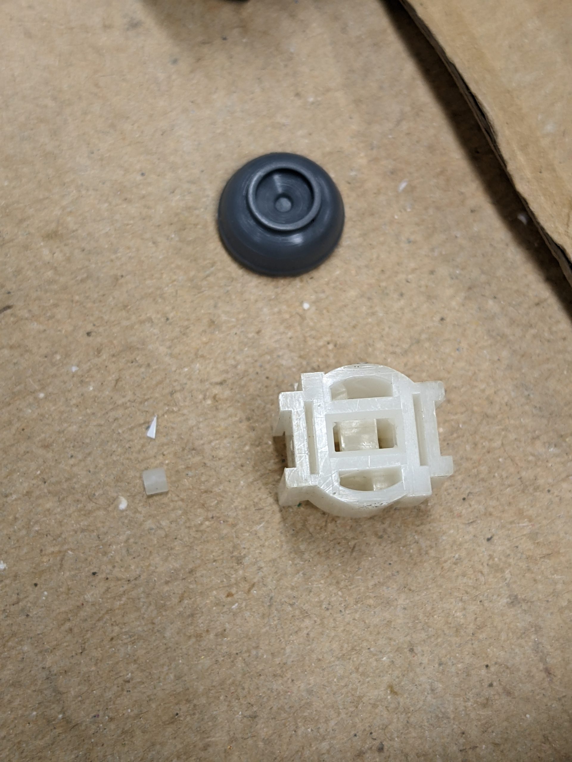
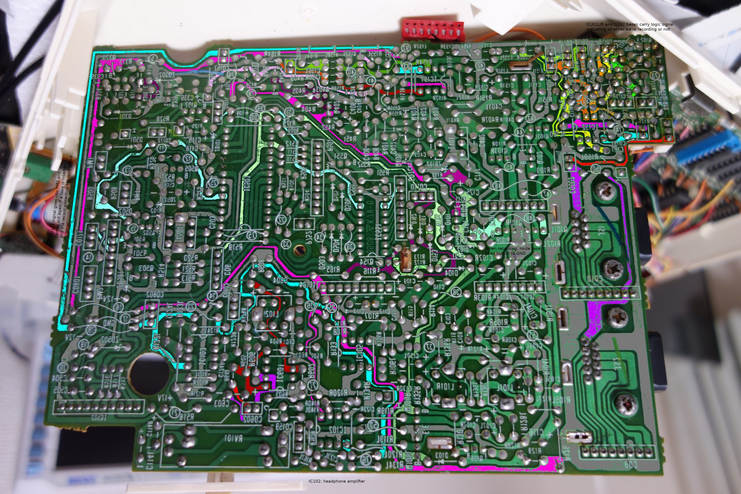
The data recorder’s reed switch to detect the record protection tab is slightly broken (you have to push it when starting a recording). (Not fixed because easy to work around)
The screen is sometimes garbled. (Fix in progress.) (At first it looked like the VRAM was partially bad, but actually, after a couple resets, the screen looked fine. It looked like it was the -5V power supply, which widely swung around between maybe -3V and -6V, and just consists of a -12V input coming from the main power supply board, a Zener diode and a capacitor, but replacing that didn’t improve the situation, so it currently seems likely to me that one of (or multiple) RAM chips for the VRAM have an unusual fault. But that’s a story for another blog post.) Update 2023/08/13: And here is that blog post!
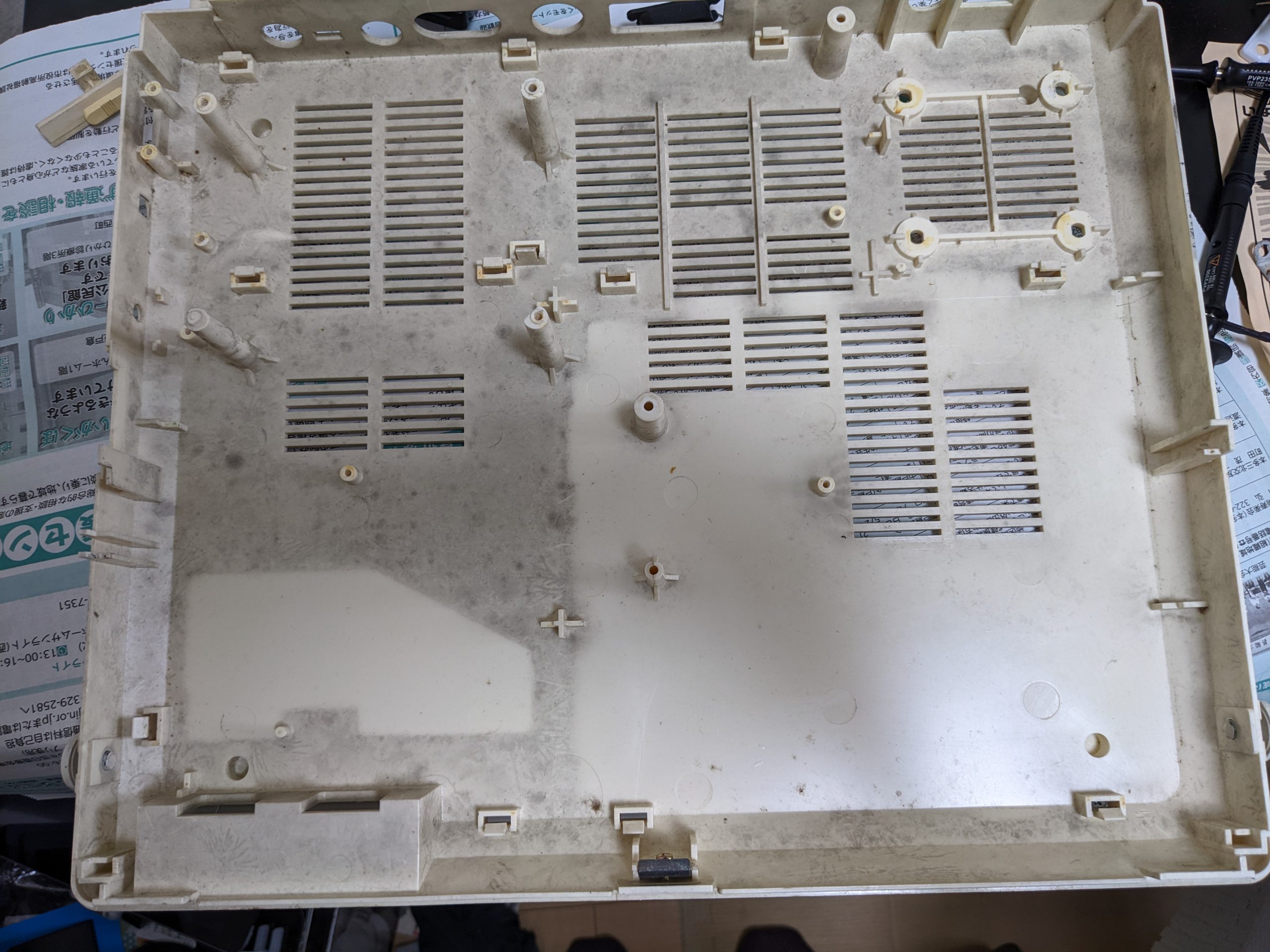
The MB-H2 had a lot of mold inside! (Fixed)
I’m not a huge fan of mold. Seeing the inside of this machine honestly made me question my hobby choices!
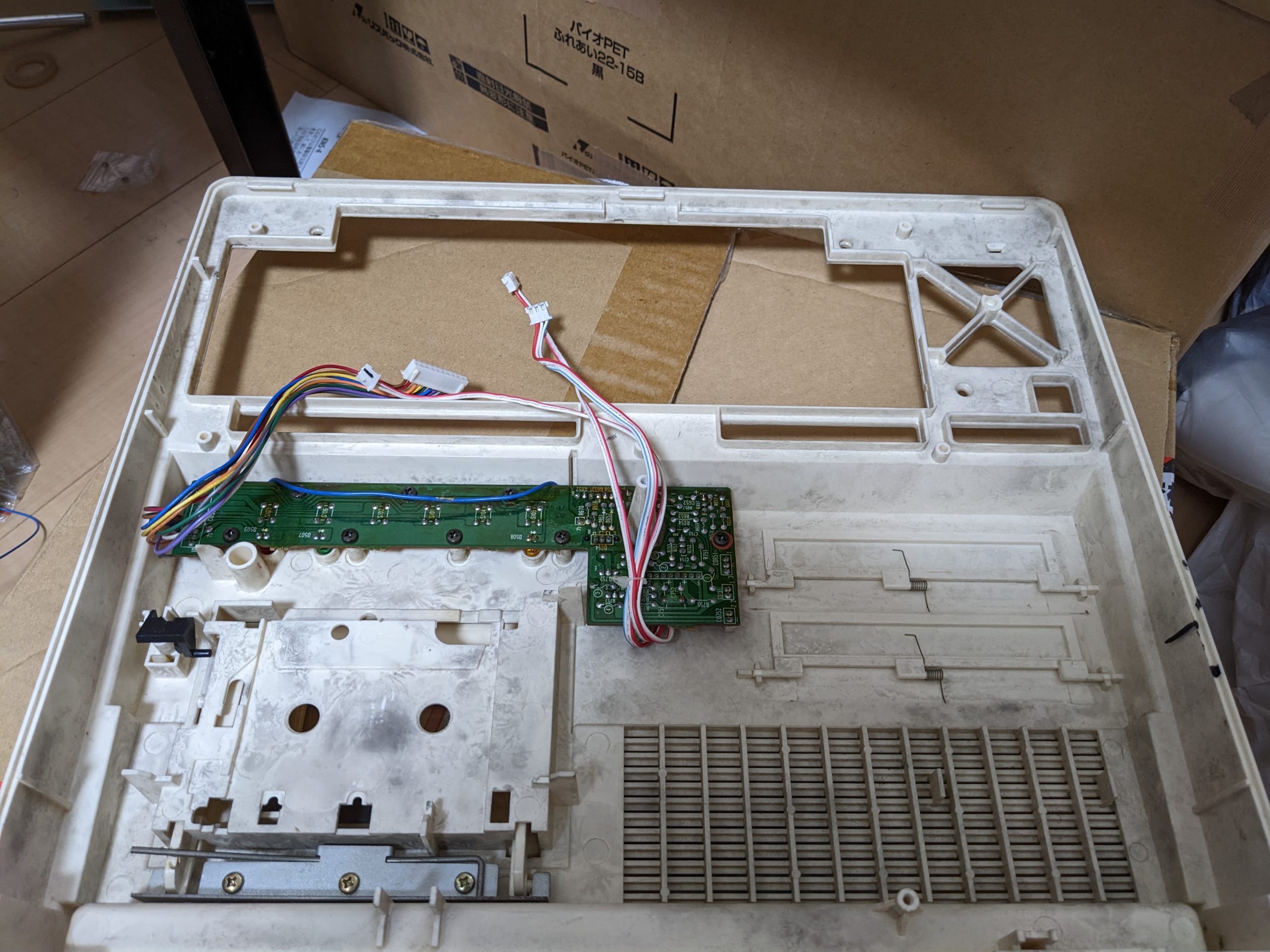
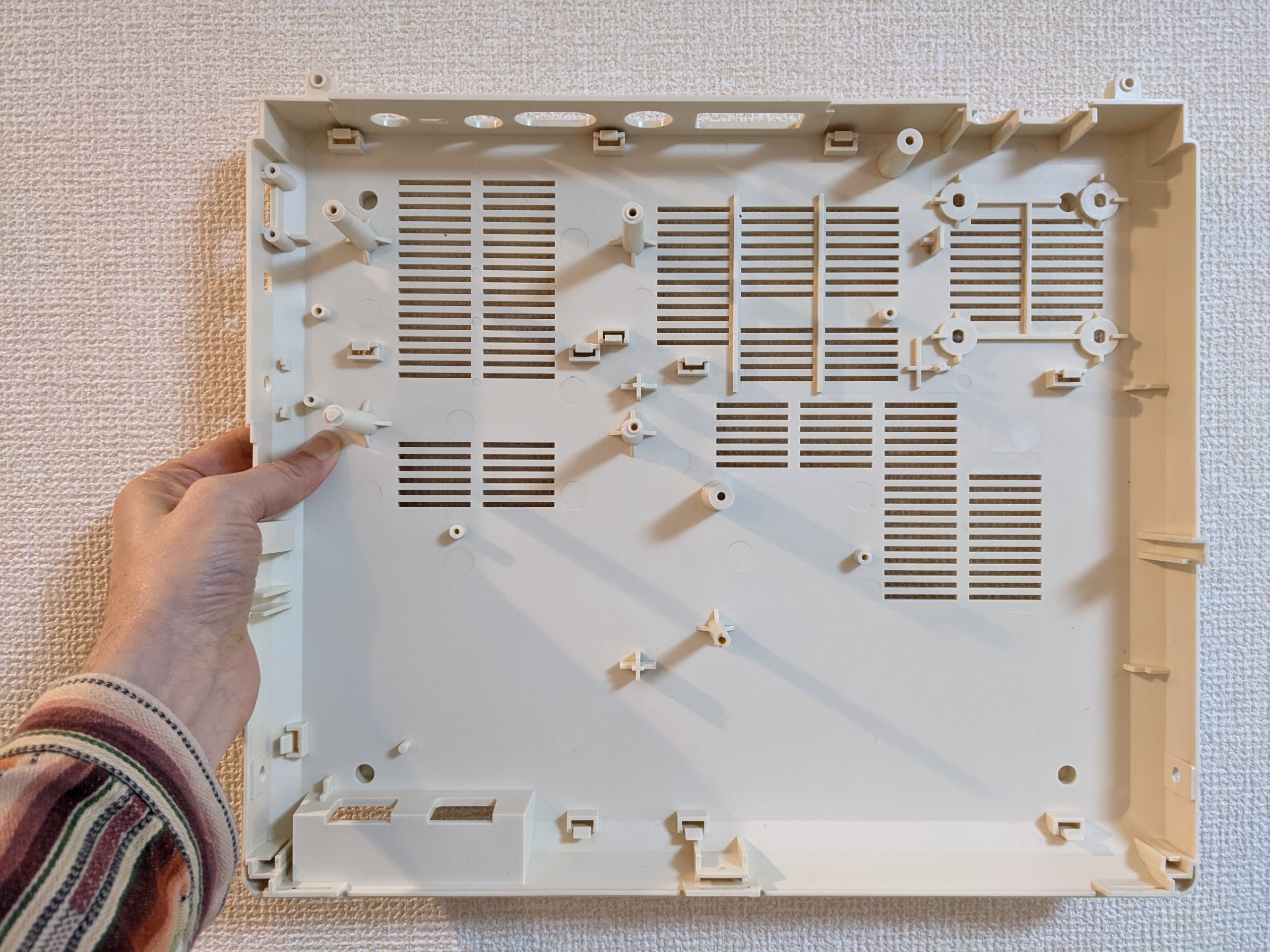
LidNot-lidNot-lid with board still in it
Eurghhhhh. I tried a couple of things:
Soapy water, rubbed in using a toothbrush. Some improvement. Maybe 70% there?
Window cleaner, rubbed in using a toothbrush. Some more improvement. Maybe 80%?
Bleachy water, rubbed in using a toothbrush. Marginal improvement. Maybe 85%?
Specialized mold cleaning solution (“カビキラー”), rubbed in using a toothbrush. Almost no mold left. Let’s say 98%.
Magic eraser (“激落ち君”). No mold left.
Should have skipped (1) and (3). I normally wouldn’t have done (1) anyway, but I was out of window cleaner. Here’s an after pic:
Looking good
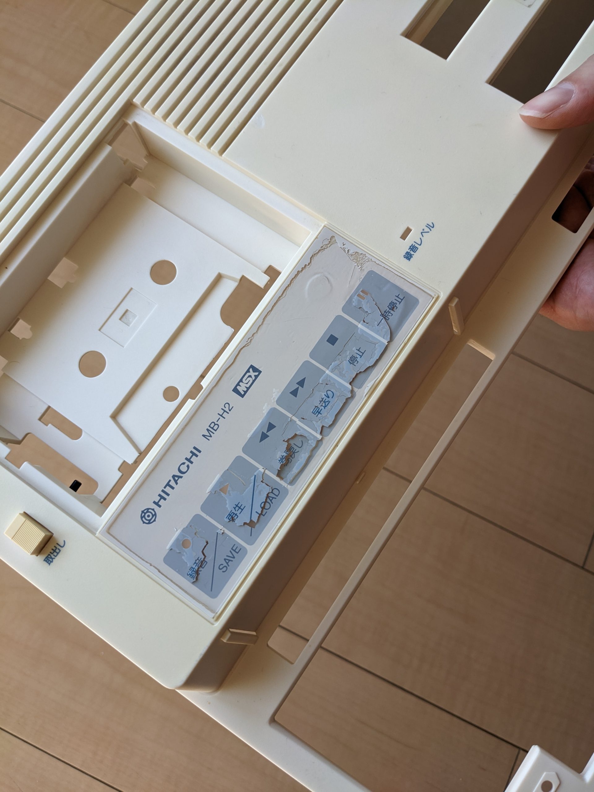
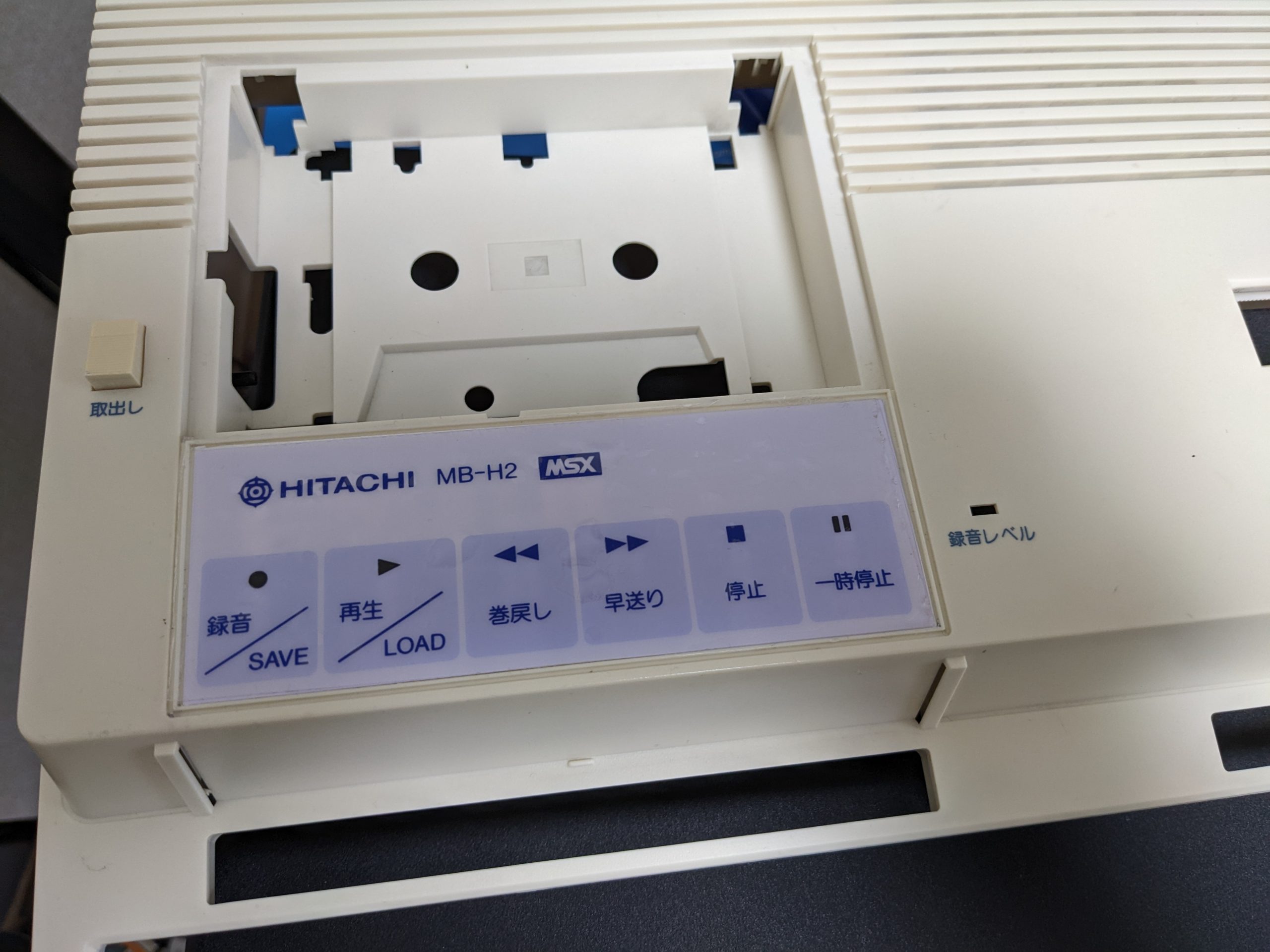
Finally, the lid had one more cosmetic problem bothering me:
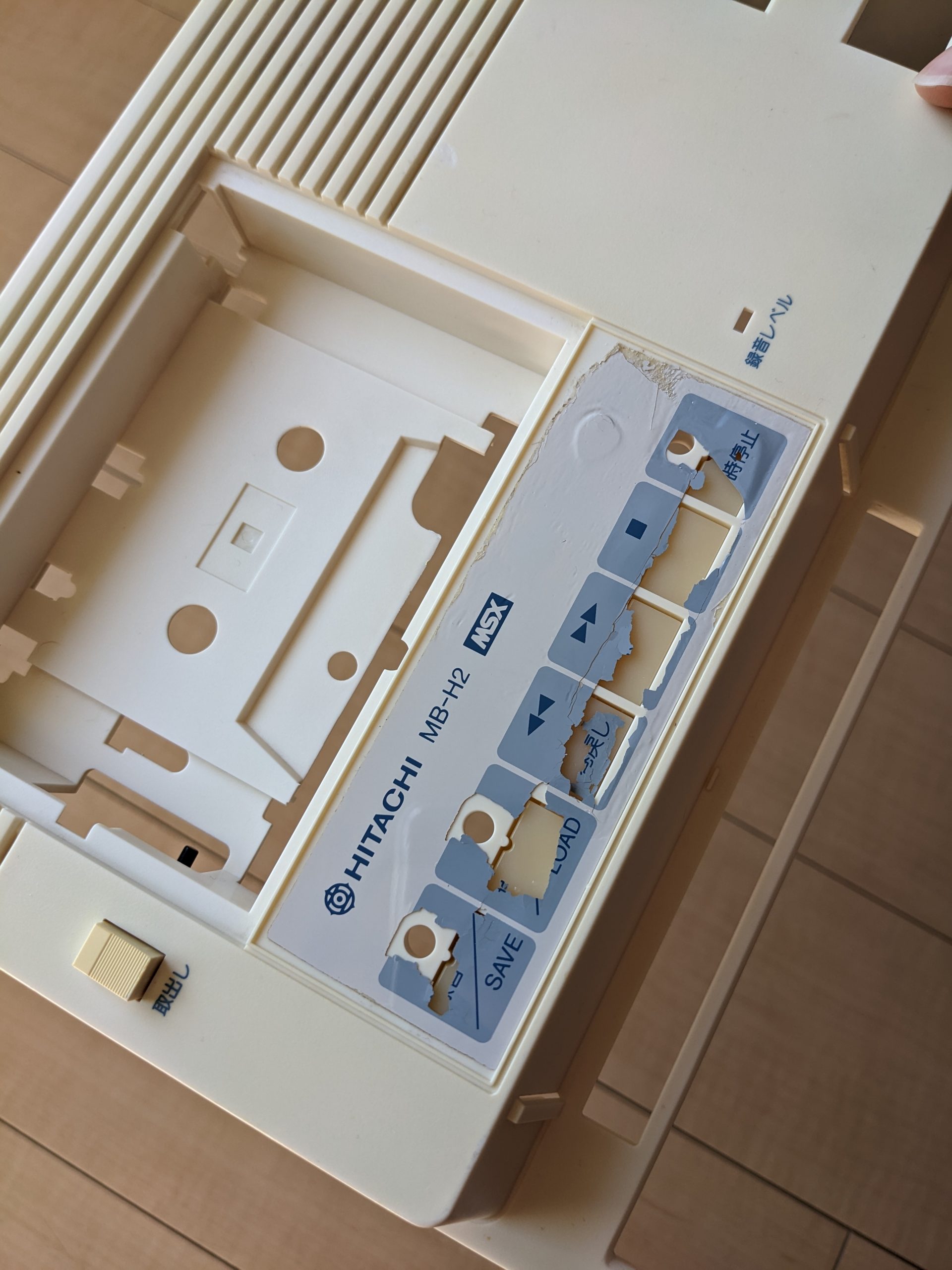
Once the (rather heavy-duty) protective plastic sticker is off (which was easy, just some prying, but YMMV), a very brittle label reveals itself, which I removed using a hair dryer and a cup of patience.
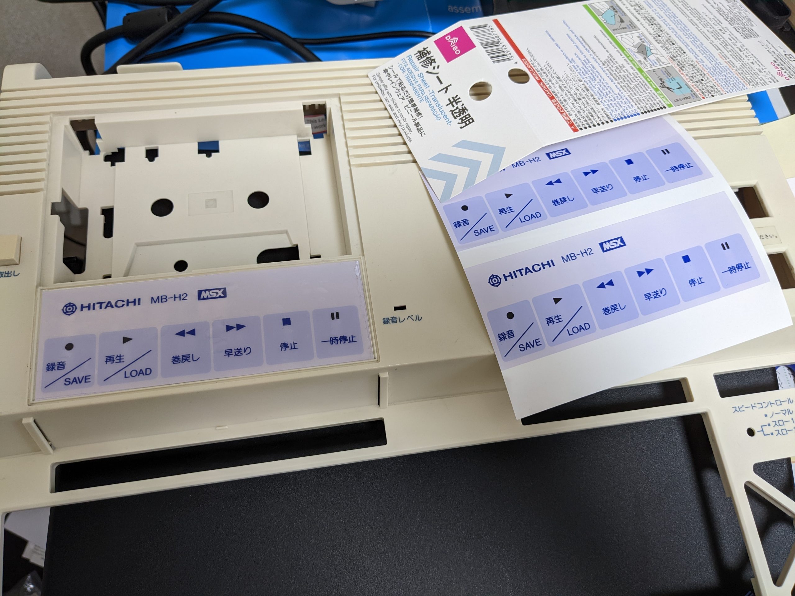
Since my other MB-H2 doesn’t have this problem, I took a high-res picture of the label, traced it in Inkscape, and printed a new sticker. Some parts of the sticker are supposed to be cut out or translucent so you can see an LED shining through. Here’s my Inkscape SVG:
And another version with three slightly different sizes (the top one is the same size as the SVG above):
Japan’s convenience store printers (at the time of this writing) let you print “2L” (127 mm x 178 mm, or 5″ x 7.01389″) stickers, and the above SVG with three different sizes just fits on such a 2L format is just a little too big for that format, though it may depend on the printer and your print margins. Still usable though!
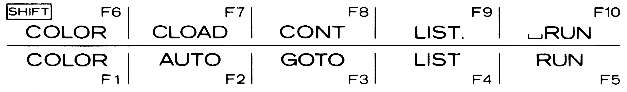
In addition, here are (400 dpi) scans of the two cards you slip into the card holder above the function keys:
The above PDF files should be exactly the correct size; you should be able to just print this on a piece of paper of your choosing without having to fiddle with the print settings. Note: Hitachi used paper that is somewhat thicker than regular office paper, perhaps post card-thick. Note: I am not 100% sure if the dot after “LIST” on F9 is supposed to be there. I believe that the Hitachi MB-H1 (and perhaps other variations) used the exact same cards.
And here’s the finished lid. I had some stickers lying around that are very easy to remove, and used those as my base, and printed my label on regular sticker paper at a nearby convenience store. I also put a slightly thicker semi-translucent sticker on top of that. (I probably should have kept the original heavy-duty translucent protective sticker, oh well.) Unfortunately the colors don’t quite look the same as the original, but they look believable, which is all that counts, right? (And maybe they’ll look closer in a few years.)
Unfortunately I screwed up a bit, you can see that the translucent sticker didn’t quite make it to the right edge. The bubbles are mostly gone by now.ダイソーダイソー♪
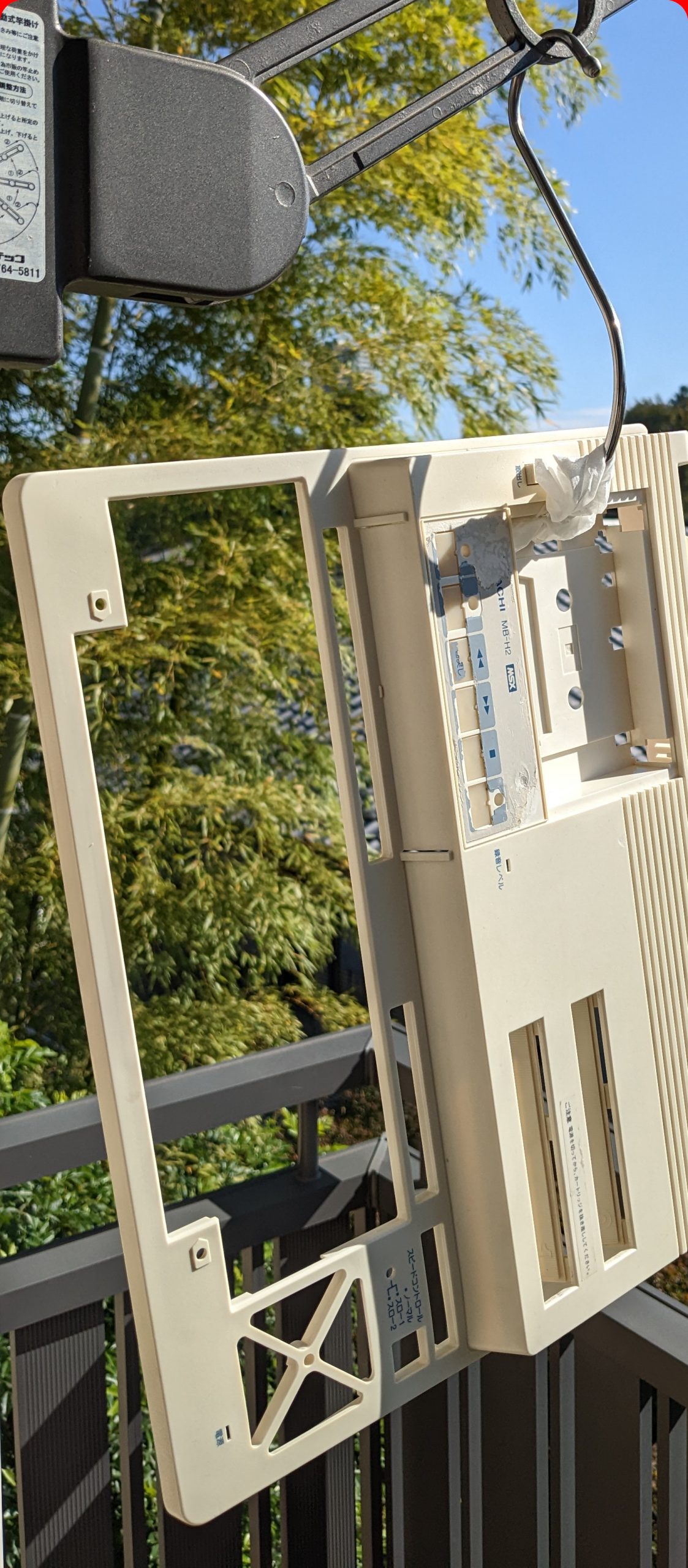
I also did some “dry retrobrighting”. In the below picture, I had left the top lid hanging in a very sunny spot for multiple days (until I no longer thought it was getting better), and hadn’t applied any intentional retrobrighting to the case’s bottom part. You can just see that the lid’s plastic is a little brighter than the bottom part. (It looks more pronounced in real life, you’ll just have to trust me on that though.)
Manual
I scanned the manual using a book edge scanner! I didn’t scan the vast majority of the book dealing with how to program in BASIC because that part is almost identical to what’s in the manual for the H1, available at https://archive.org/details/Hitachi_MB-H1_documentation/. (Except for occasional explanations of H2-specific features, such as “CALL HCOPY”.)
I did scan the parts of the BASIC reference detailing the cassette-related keywords, though. I also scanned the pages detailing the monitor commands, only later realizing that the H1 has these pages too. There are some differences though, so phew I guess.
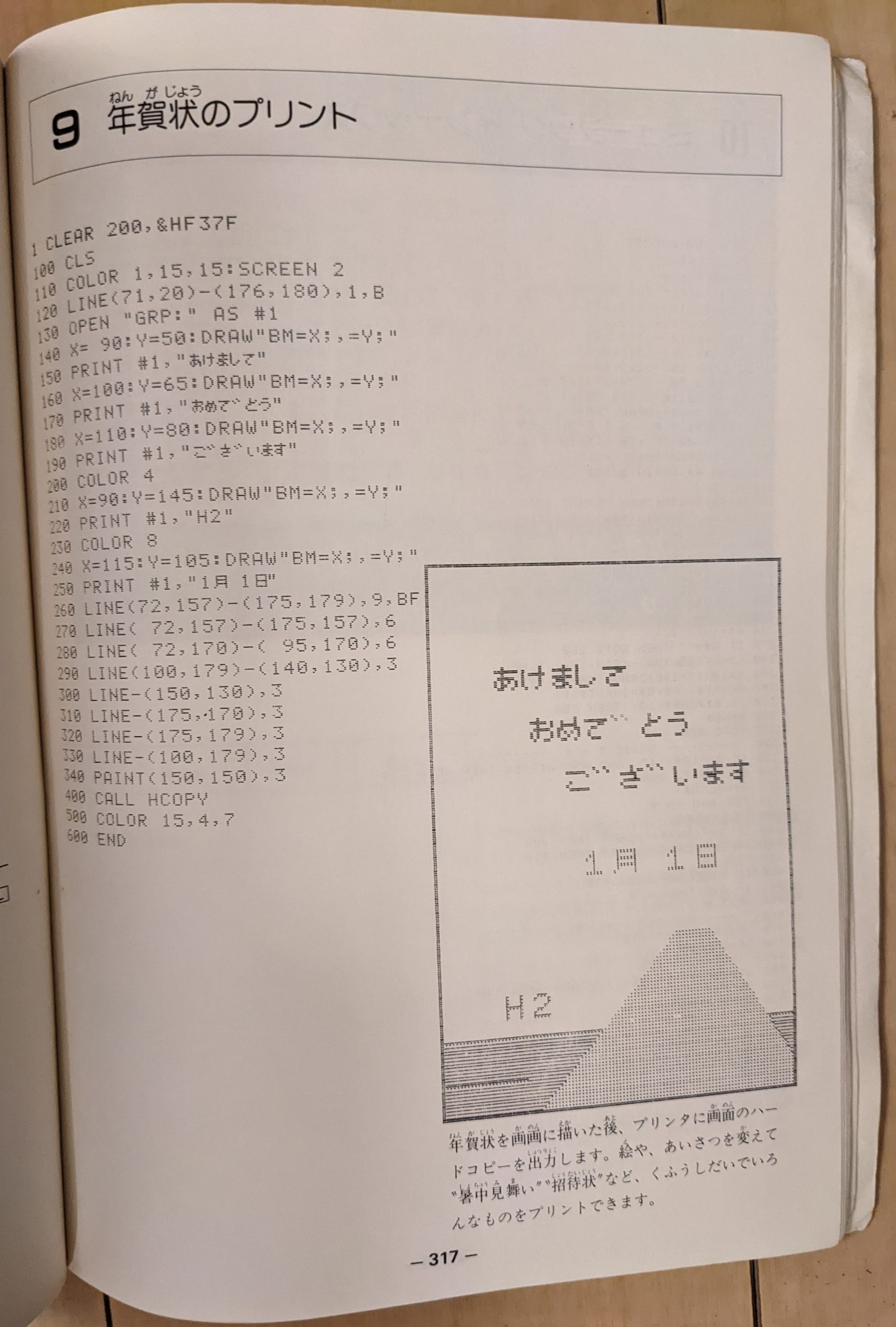
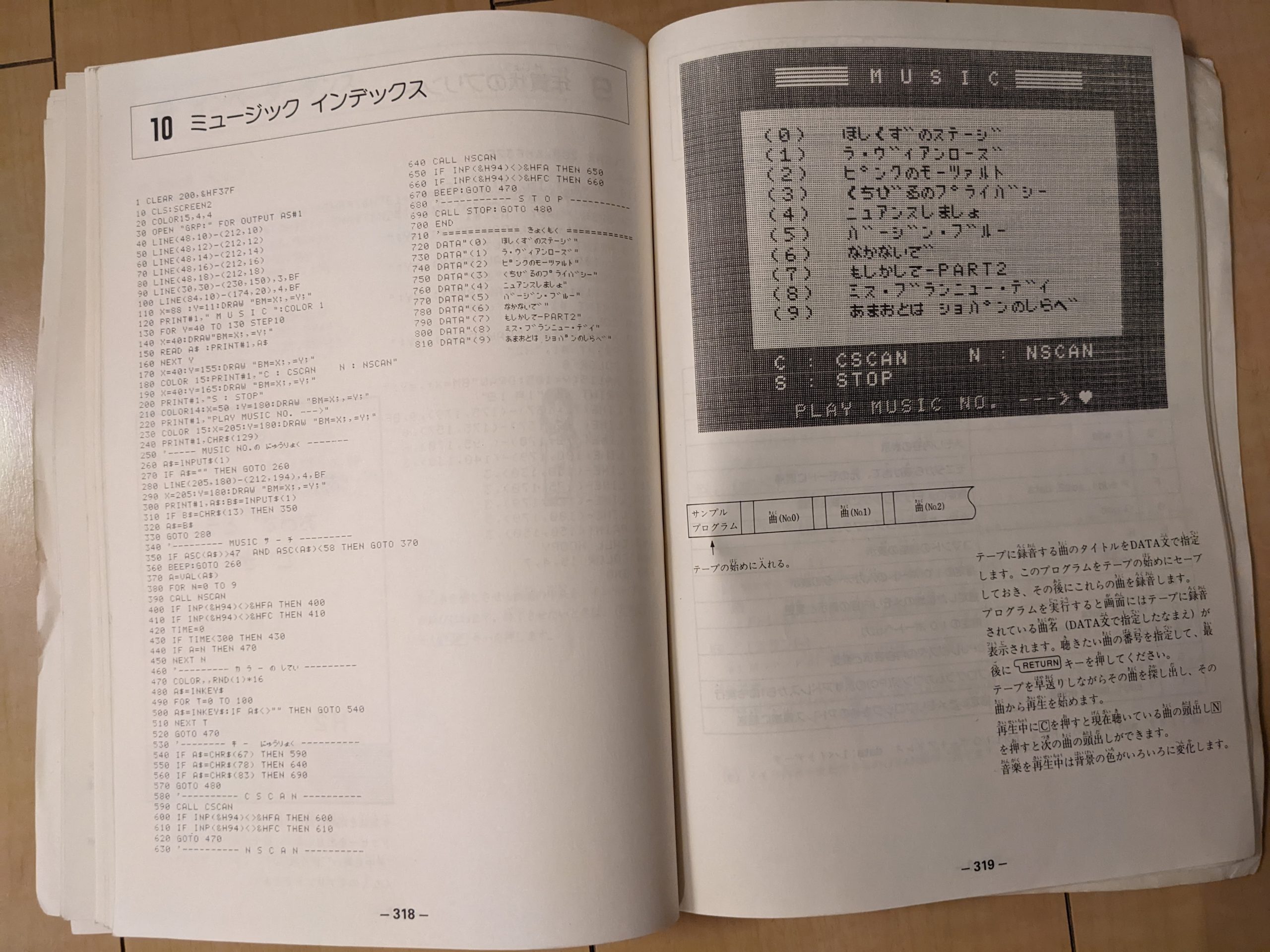
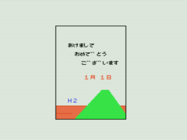
I only just now realized that the manual for the H2 contains two extra sample programs not included in the H1’s manual. I didn’t include them in the PDF but since they are cute, here are pictures:
Symptoms: black screen, no sound, no activity whatsoever.
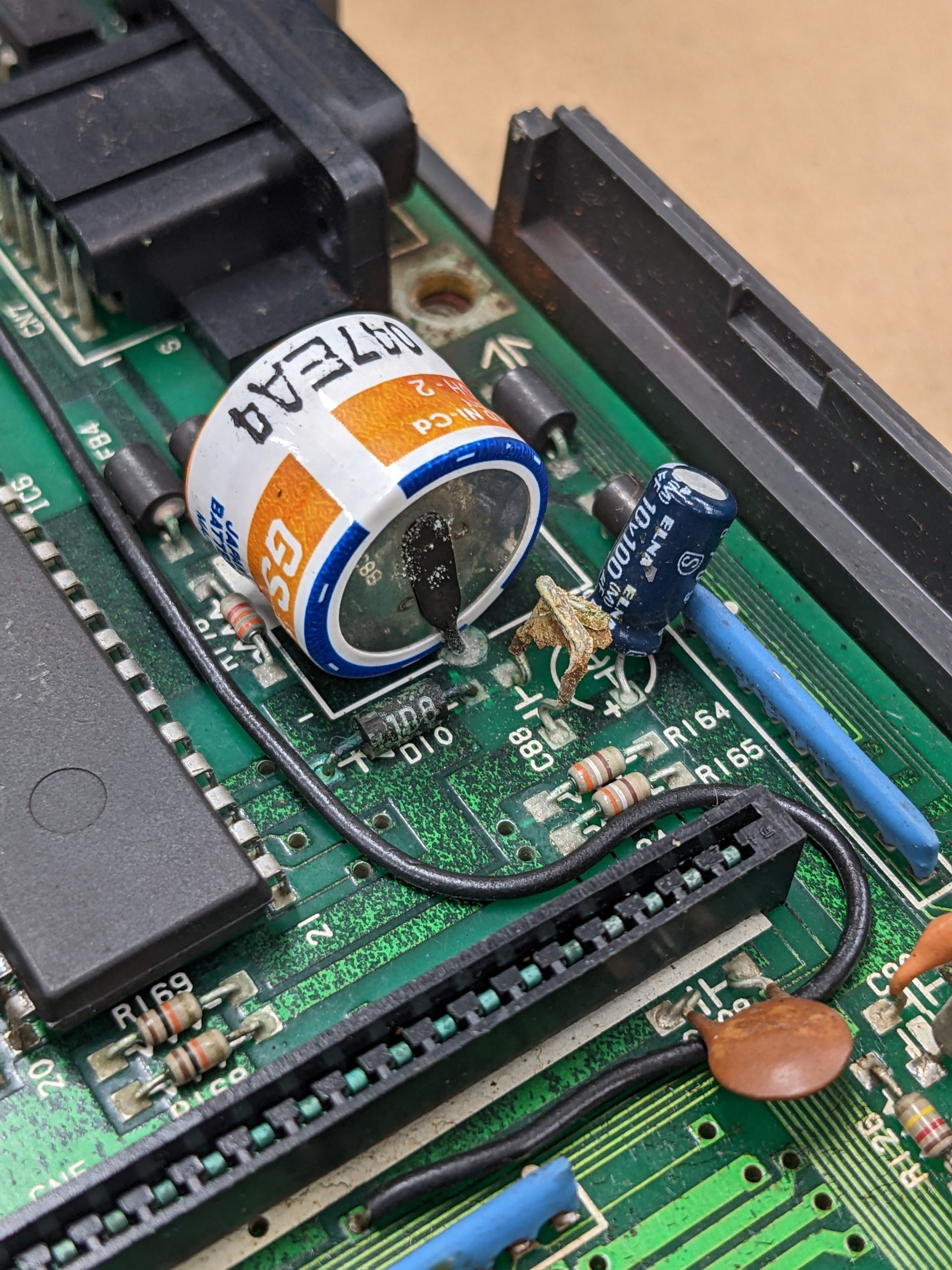
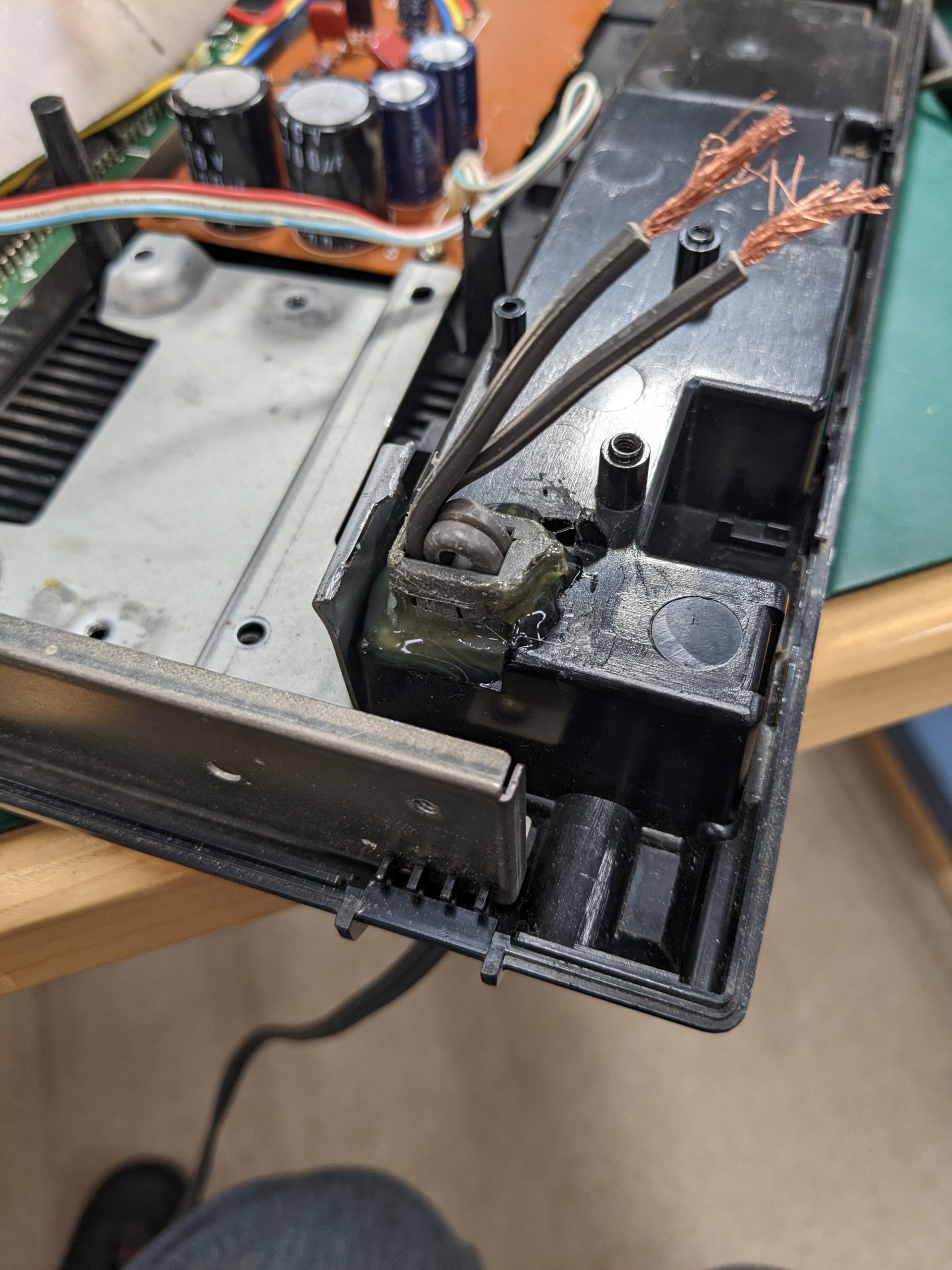
Summary: this machine contains a NiCad battery, which leaked. The machine started working after cleaning up the leak. That’s the good part. Let’s jump into the nitty-gritty.
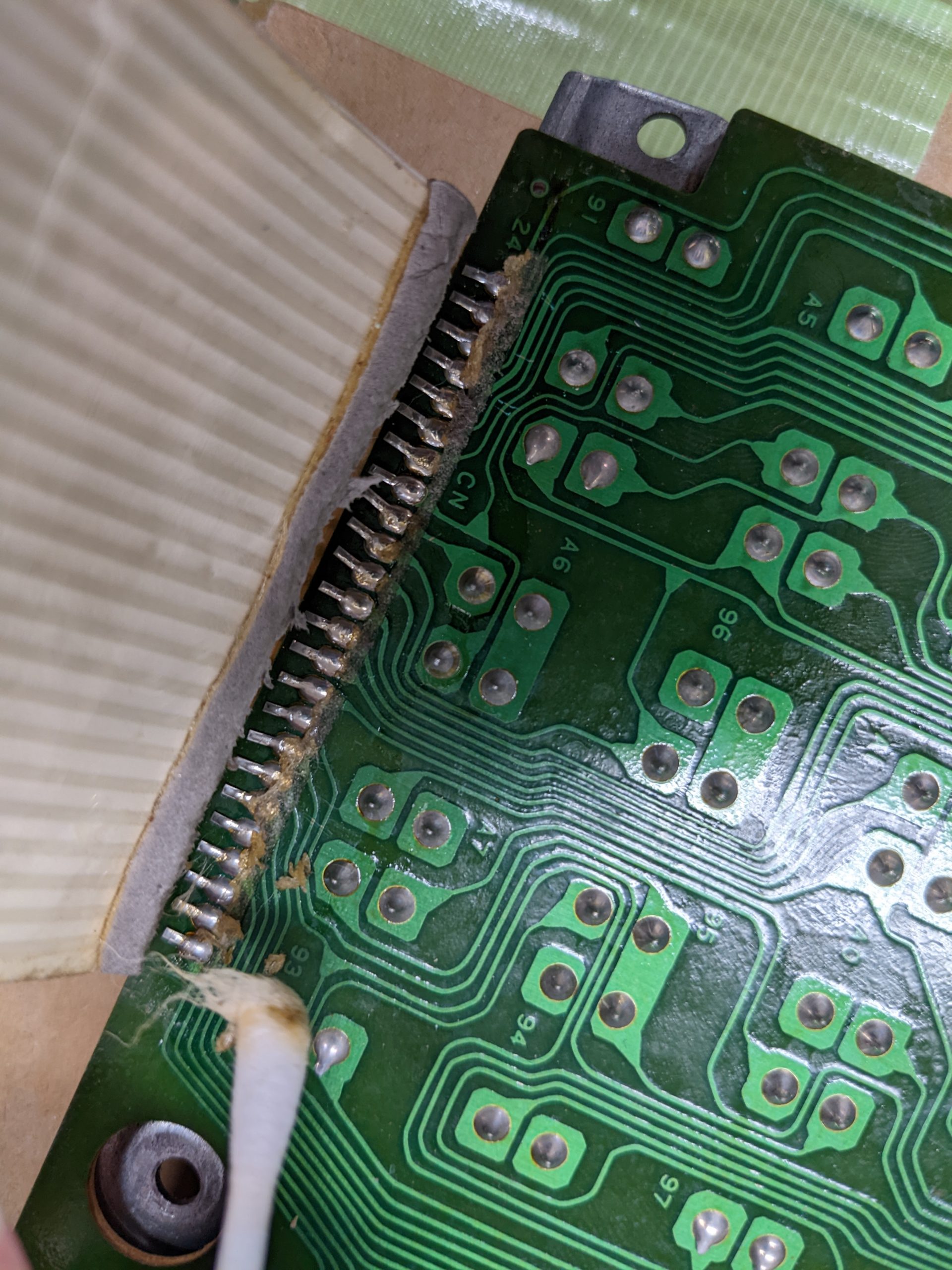
That doesn’t look so bad?That looks bad! Rest in peace, C88, keyboard connector, and various traces(?) D: TBH, I thought this’d be a no-fix at this point.
Some electrolyte also made its way up to the keyboard PCB. All these traces tested fine.
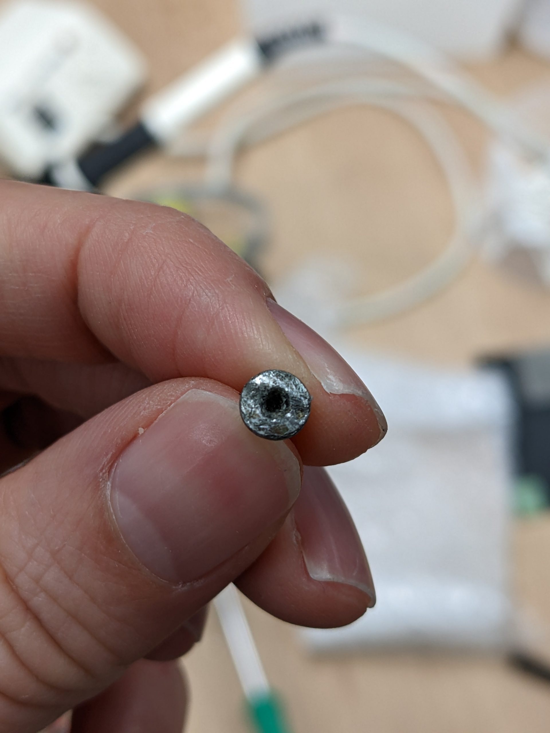
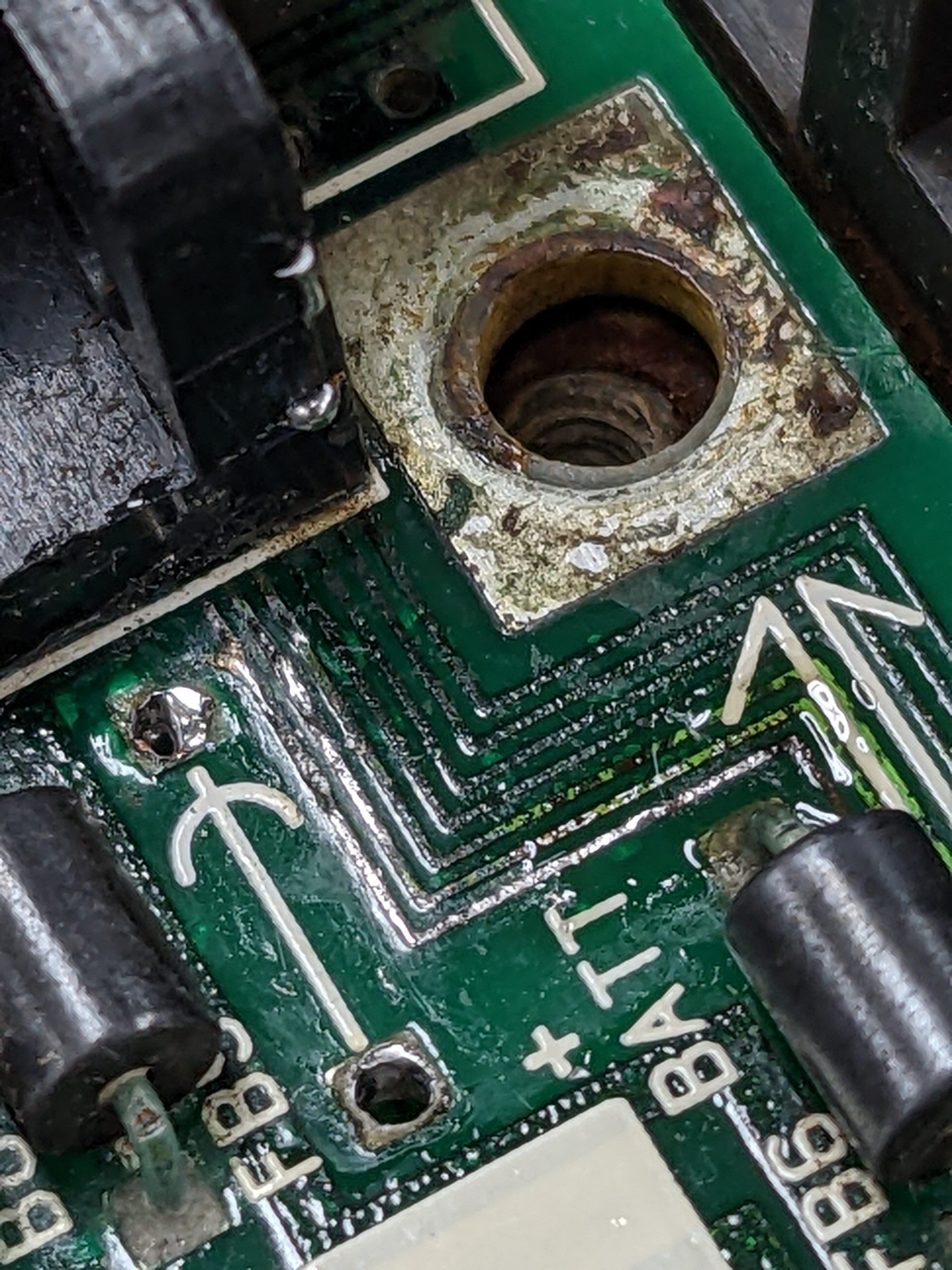
The first step is to remove the battery. The second step is cleanup. Fortunately, all internet sources I read stated that cadmium doesn’t leak out of the battery, just the electrolyte (maybe at ppm or ppb levels, but nothing to worry about IMO as long as you don’t use your bare skin or tongue to clean up the leak). There are various sources out there about how to best go about the cleanup. I only used IPA for now. I’m thinking of giving it a water bath… But I’m too much of a chicken. D:
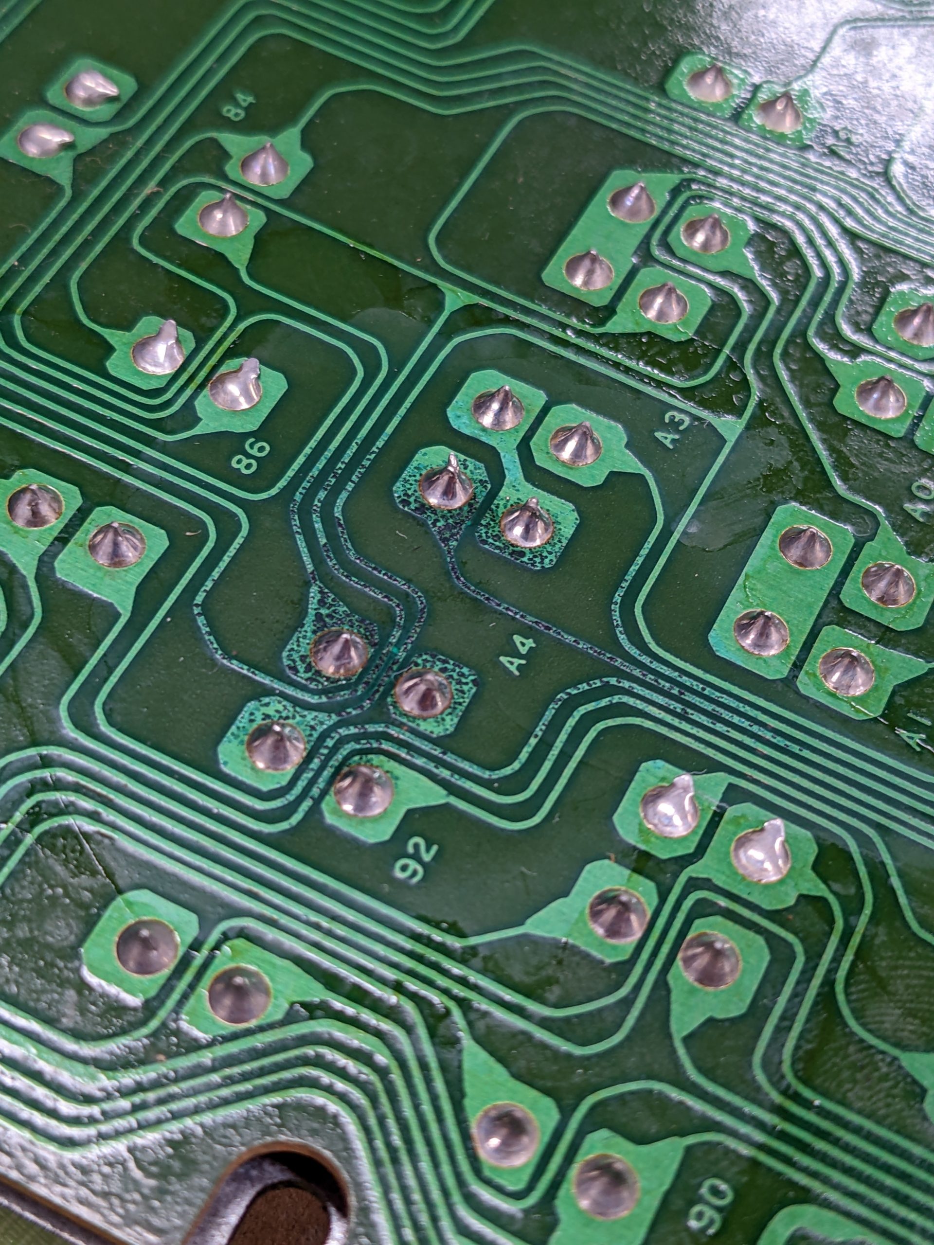
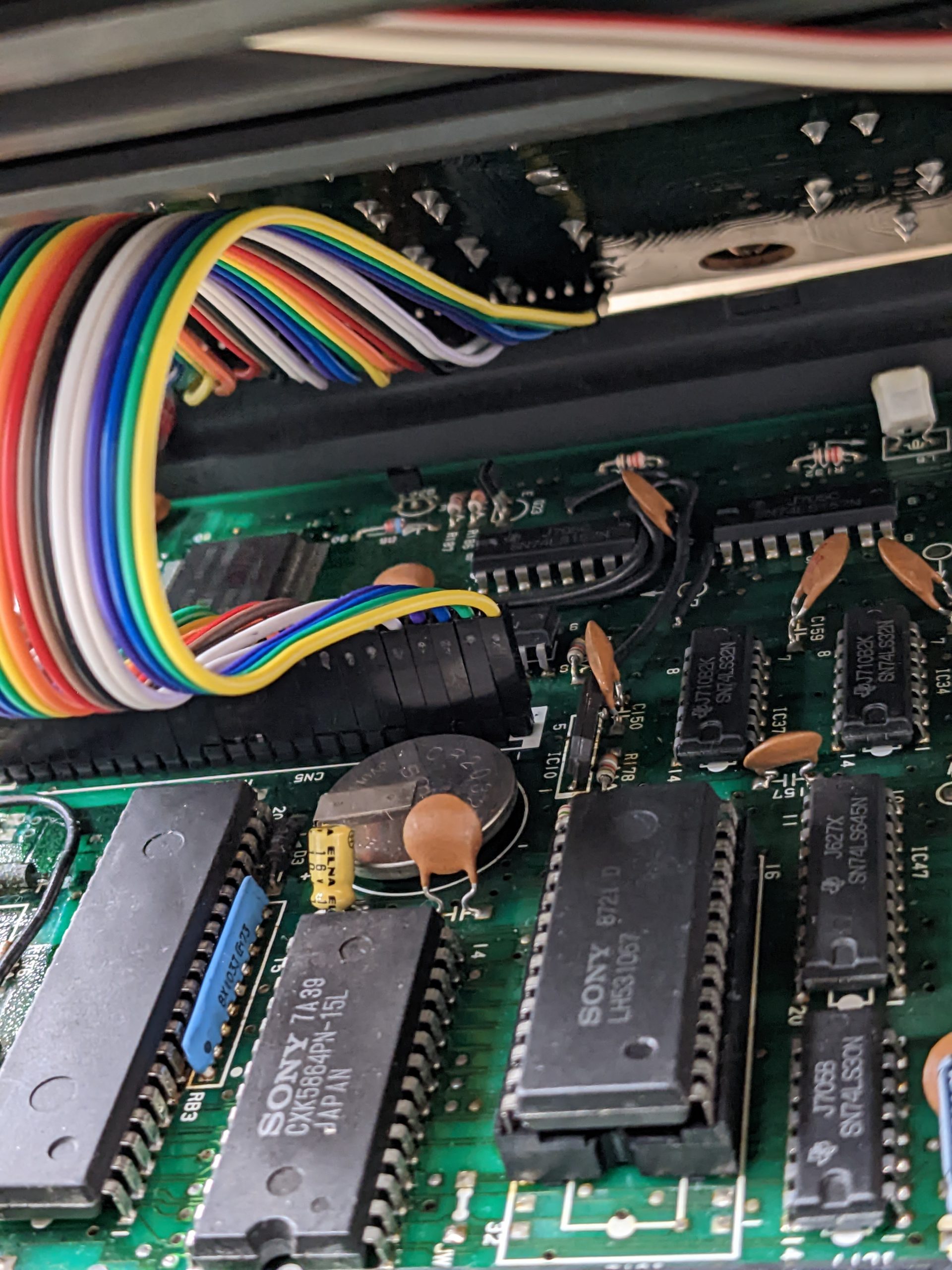
The NiCad battery destroyed a joystick trace, which prevents one of the joysticks from working correctly. (The traces to the right of the NiCad battery, right at the edge of the board, are for the upper joystick.) Unfortunately, this trace goes into a SMD chip, the Yamaha S3527. With through-hole chips, we could just add a bodge wire on the back of the board. With SMD chips, we have to repair the trace. I elected to skip doing this, as I’m not sure where the trace is broken. Judging by the visuals, it could be broken along its entire length or in multiple sections. Also, adding a long bodge wire on the top of the board seemed kind of messy. So we’ll live without one of the joysticks for now.
Edit 2022/12/04: I repaired the trace. I scraped off solder mask in various places, narrowed it down to a small region, scraped off more solder in that region, and tinned the trace. (I used my poor multimeter probes to scrape off the solder mask.) That made it a bit easier to find the exact location of the two breaks. I ended up using solder to bridge the breaks. These traces are tiny, and I also had to take out a ferrite bead to get to the right one. And of course, while soldering the ferrite bead back in, I melted the solder bridge and had to have another go at it. Though it was much easier of course as it was already mostly there. As the drop of solder could break off, or nearby rework could break the trace again, so this isn’t the best way to fix it. It would probably be best to solder in a very tiny wire.
Note: the camera used to take this picture is probably AI-interpolating, so it doesn’t really make sense to look at the hi-res version of this image.
The battery leak also destroyed a capacitor (C88) and the flexible cable for the keyboard (and its connector, more or less).
This picture was taken before I managed to open the computer. (Which was quite hard! Definitely the least “repairable” computer in this bunch.) I’m guessing that the previous owner probably opened this computer once (as there were a couple screws missing too) and this cable had already been exposed to the electrolyte at this point, causing the metal to separate from the plastic? Something like that, anyway.
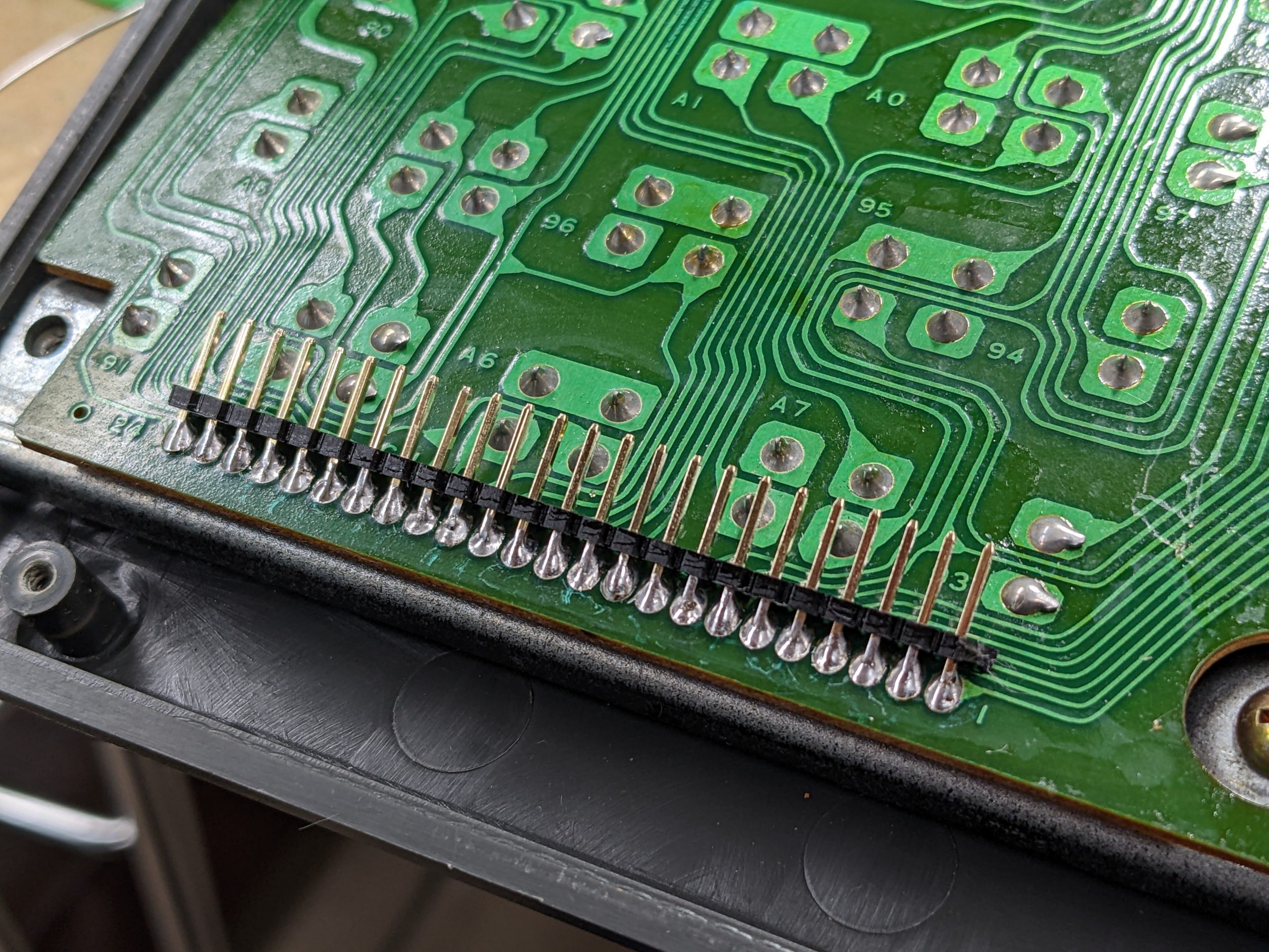
I desoldered the keyboard connectors (both on the keyboard itself and the mainboard), and added pin headers instead. Here are some pictures of the removal process:
Using a knife to remove the stress relief(?) fabric.At this point we can clean up the remaining bits of fabric with a couple cotton swabs dipped in IPA.New pin headers on the keyboard PCB. These pin headers have a 90 degree bend. I made them point up a little bit though.Bad quality and vertically long video showing how to loosen the pins after sucking away the solder. (This is the keyboard connector on the mainboard.)Traces underneath the keyboard connector are looking bad, but are actually still okay.This wire was too inflexible, the DuPont connectors are a little too high, the wire was too long, and unplugging and replugging is a lot of effort.
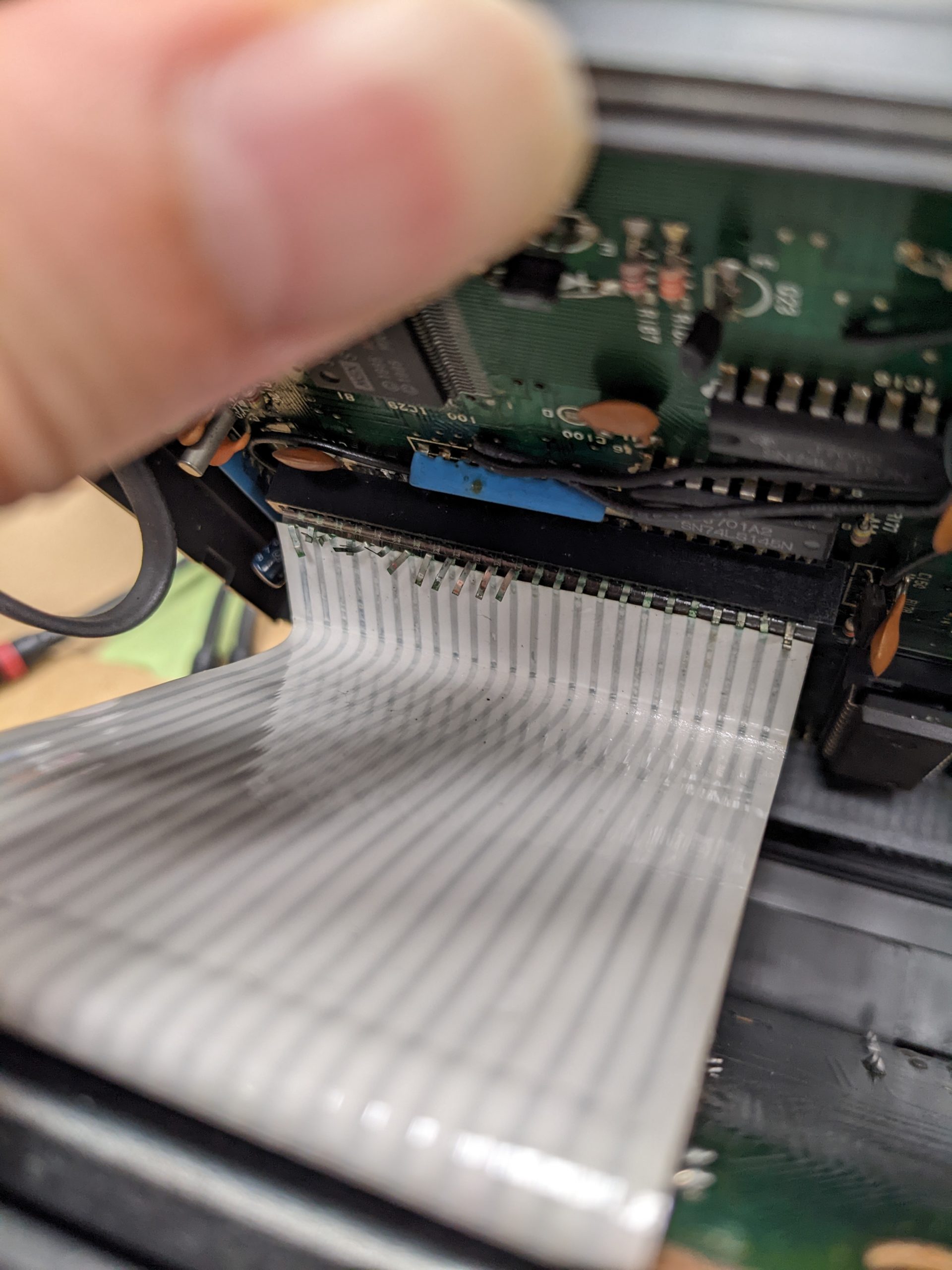
I’d planned on just running jumper wires with DuPont connectors, but my jumper wires were too long. The keyboard worked, but I was no longer able to fit the computer’s lid on its case because the jumper wires would bump against the cartridge slot. Putting on and taking off the jumper wires one-by-one was pretty annoying, so I decided to use a ribbon cable as used for IDE drives, plus four of the jumper wires. That made it pretty easy to plug and unplug the keyboard, which is useful when switching between software-based tests and hardware fixes. However, the lid still wouldn’t fit very well. It was just barely possible to close it, but it very much relied on the screws to hold it in place.
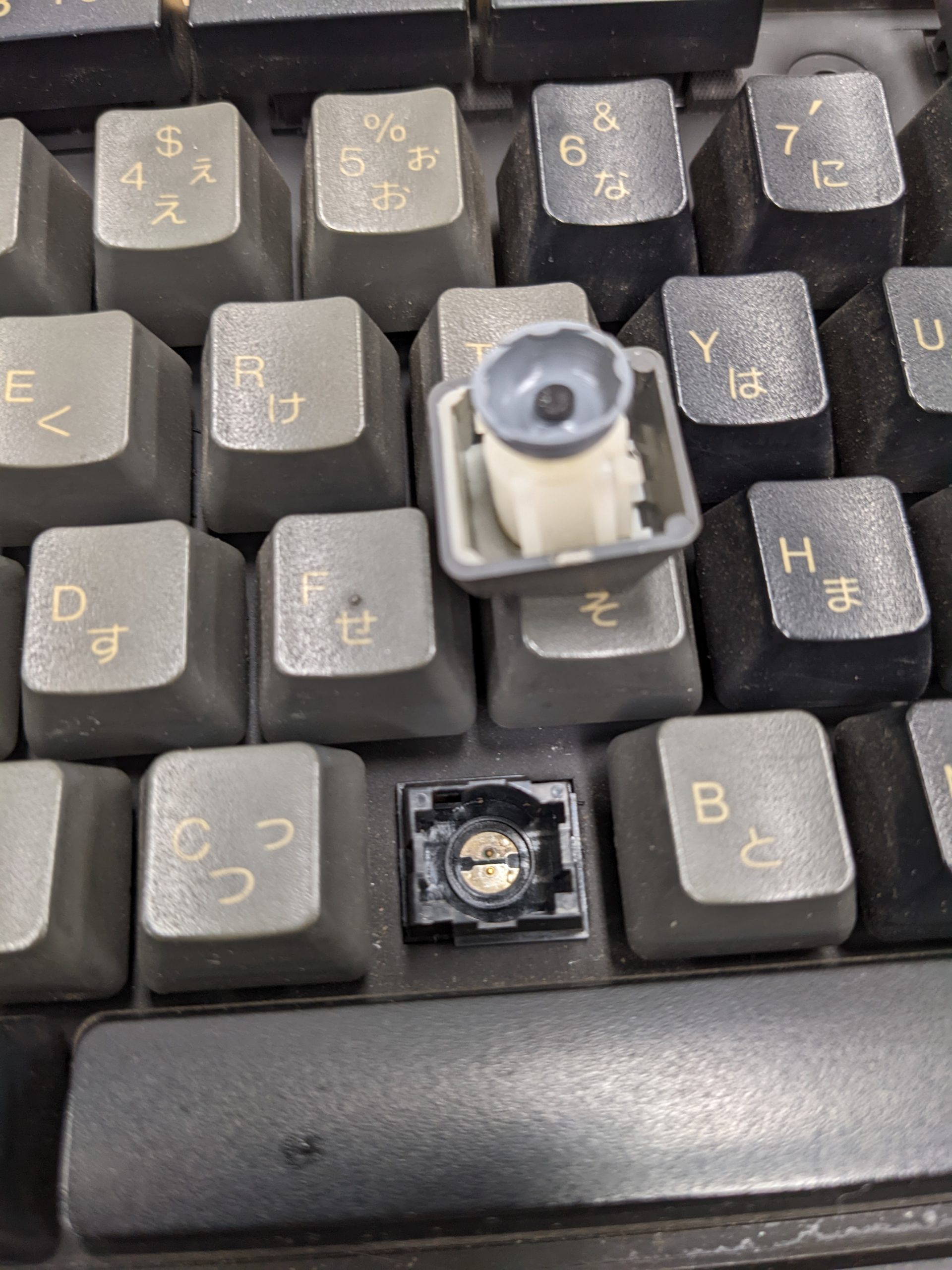
The keyboard had a couple of non-working keys. The keyboard isn’t very “repair-friendly”. Each key switch has two little feet. When taking out the key switches, you are likely to break them off.
When pulling off the key caps, the key switch will sometimes come off as well. If you’re unlucky, you may already have broken clips on the key switch at this point.Usually, when pulling off the key caps, they will separate from the key switch below. However, to clean the metal pads below the key switch, you have to take out the key switch. Do not use pliers like I did in this image, or you’ll risk breaking the clips.That white bit of plastic isn’t supposed to come off, but if you use pliers it probably will! On the bright side, there are two of these clips, and one is generally enough to hold the key cap + key switch into the keyboard assembly. I’m guessing that there is a special tool for these key switches. Or maybe you can put in a fine piece of metal (e.g., a dull needle) somehow. I don’t know. :(
HB-101
This machine just worked. The keyboard was filthy, so I cleaned the key caps using my ultrasonic cleaner. Removing the key caps was straightforward.
Dirty key caps.
Some time passes…
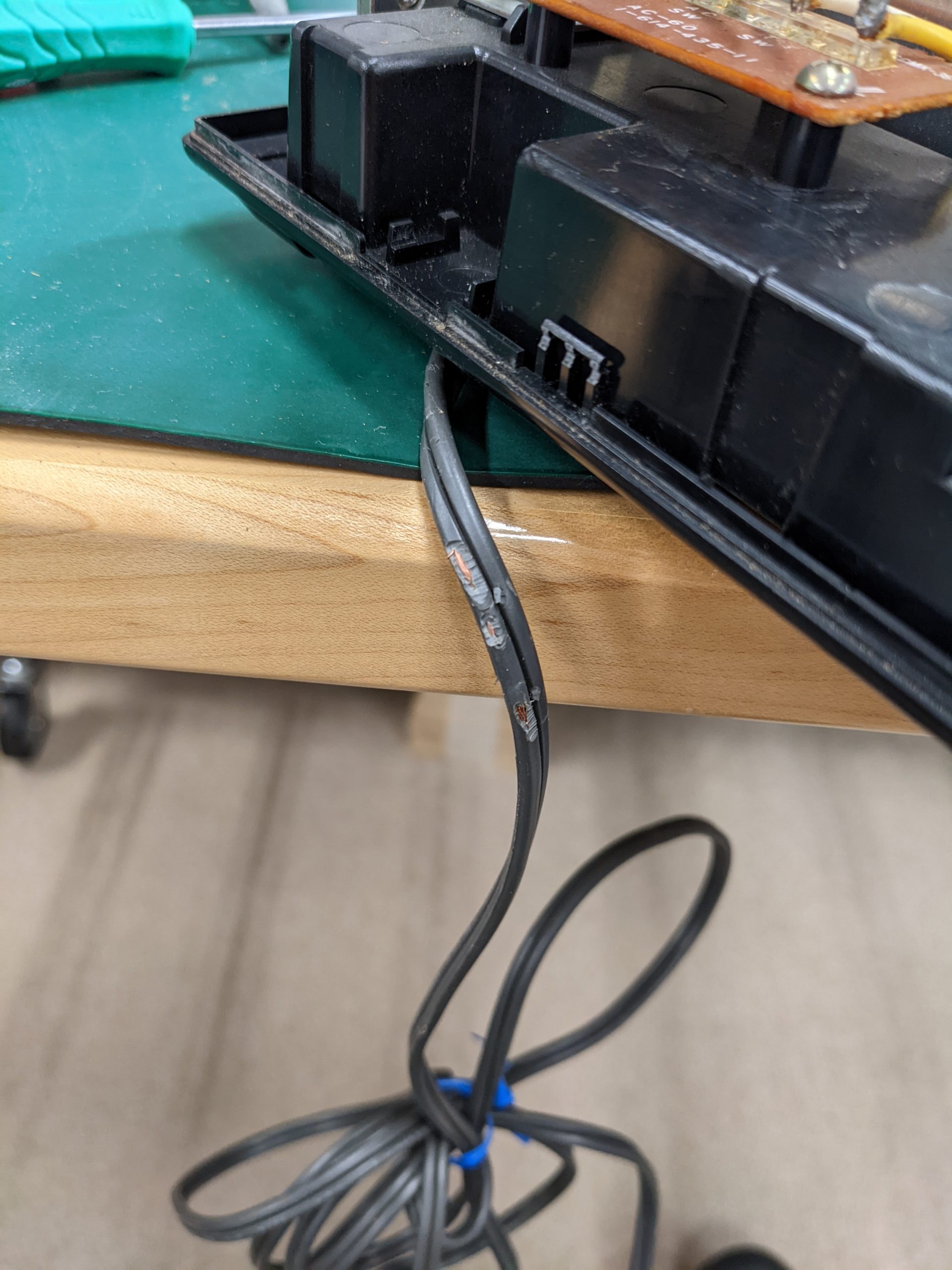
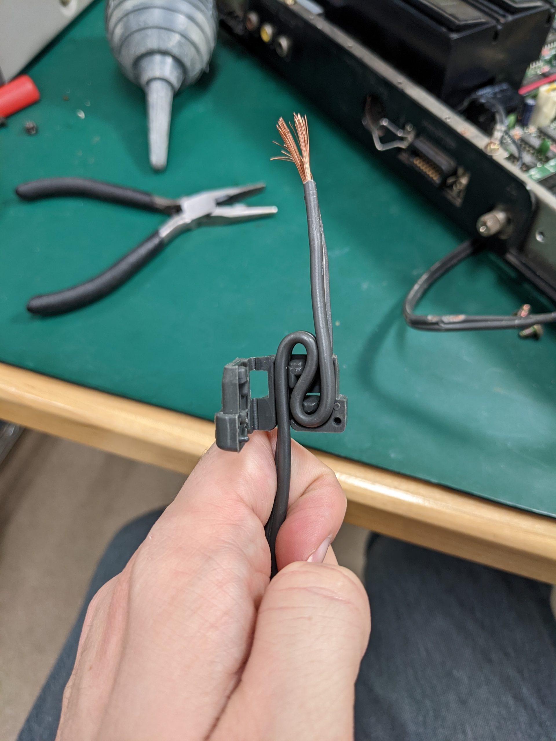
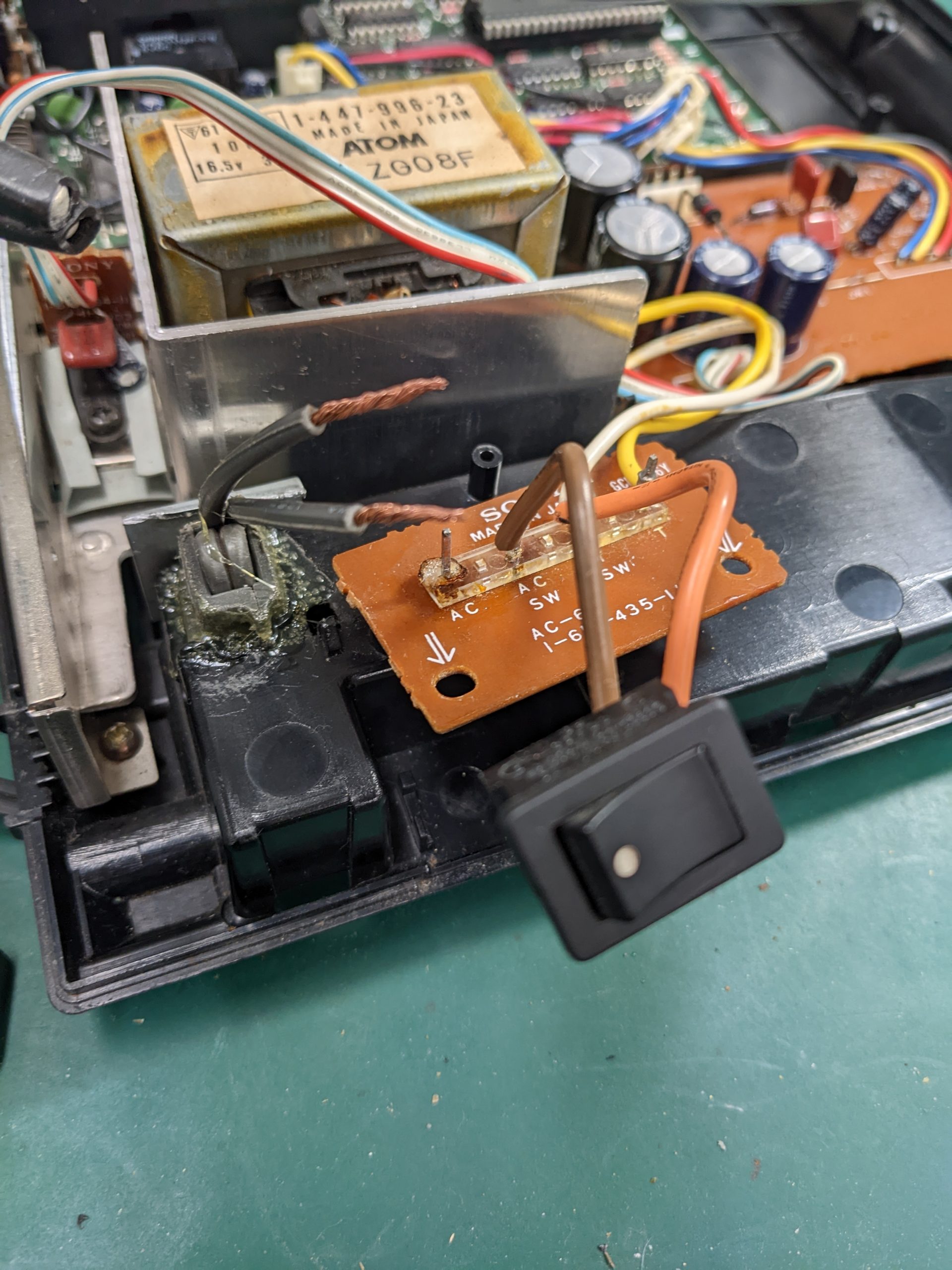
… Oh, that power cable looks safe, doesn’t it?
Maybe it’s a good idea to, at the very least, first of all examine the power cable before plugging in old electronics. I fixed the cable by cutting off this section, which meant I had to desolder the old section from the terminals, wire strip, and re-solder.
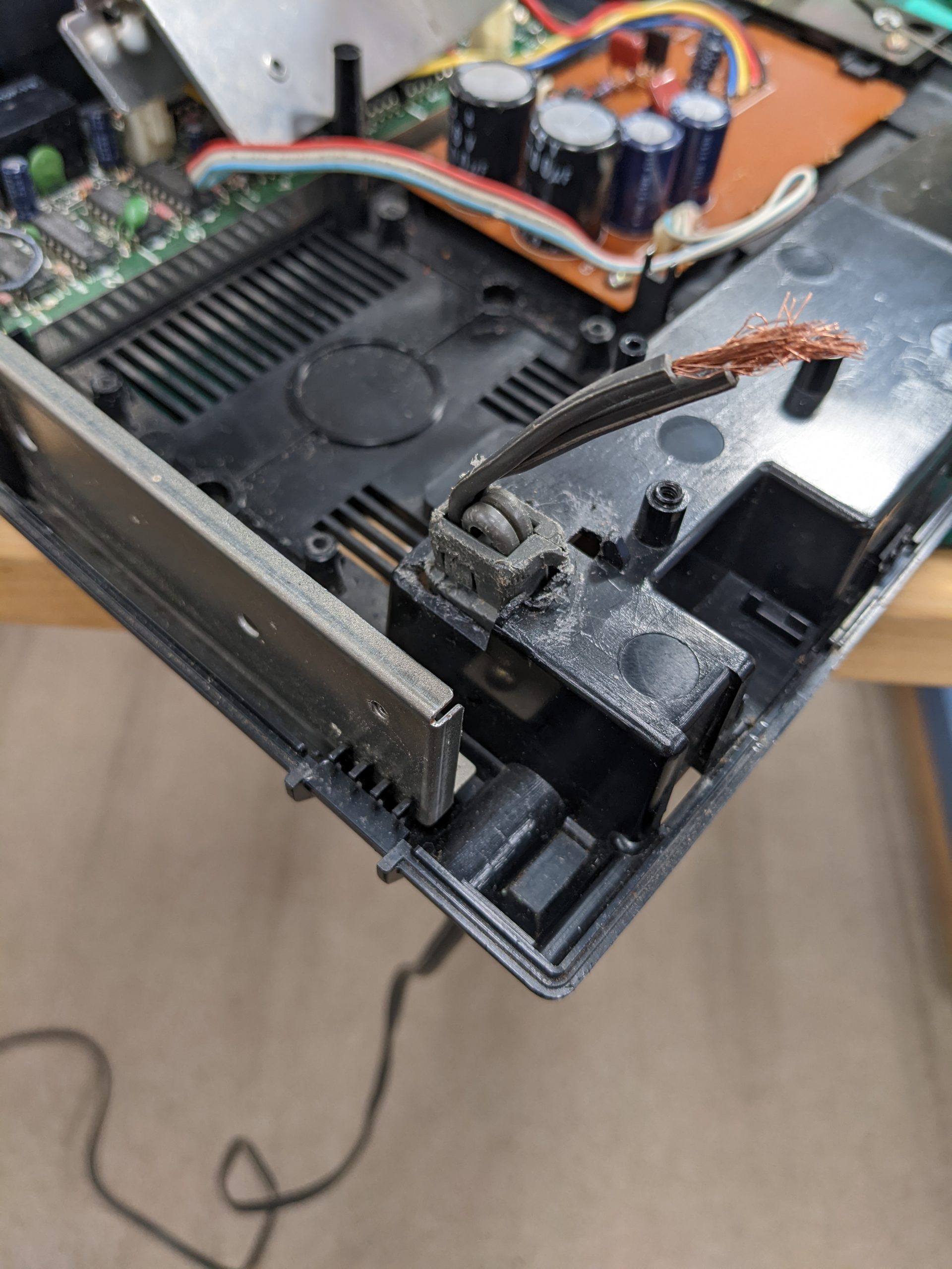
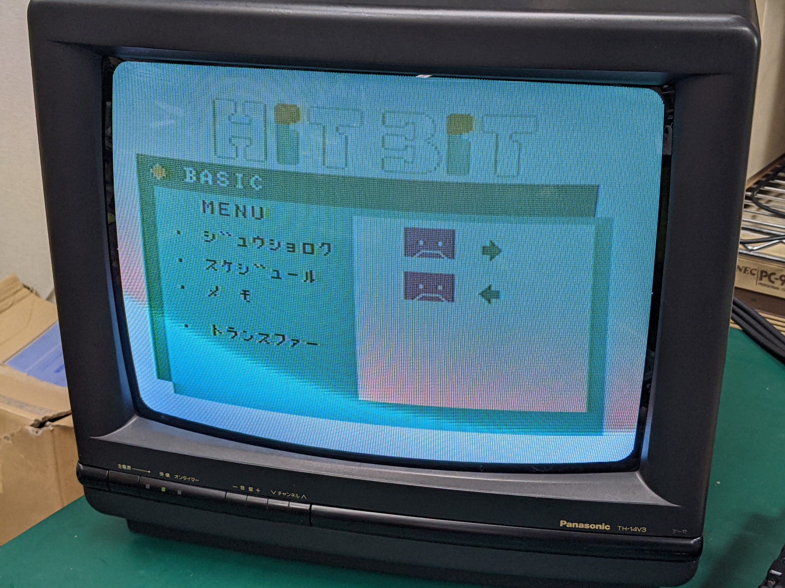
Stress relief thingy, not scratched and generally looking fine.Stupid stress relief thingy, finally mostly in place but not quite. Scratched. Had to cut off some plastic. It’s still not 100% tight. Cut my finger too.Glue. Take that, silly stress relief thingy.Hardened glue. Also started desoldering the existing wire. Unfortunately melted the plastic a bit. Better to first desolder the pin from the back side of the board, then desolder the wire wrapped around it.Apparently I forgot to take a picture after cleaning up. But here’s the machine, booted. Those tape icons look like unhappy faces, which had me worried for a second.
HB-11
Just broken solder joints on the AV connector.
Just touching the AV connectors a little bit.This was two months ago. I don’t remember whether this is before or after the repair. These bodge wires are factory and presumably help a bit even if the AV connectors are manhandled too roughly. (Or perhaps the audio pad was already broken at the factory?) BTW I think audio broke again. I’ll take another look sometime soon.
Update 2022/12/03: Audio was indeed broken again. Bad solder joint on Q2’s emitter. Factory didn’t use enough solder. Hardly any solder, in fact. Fixed.
Summary
None of these repairs went off without a hitch.
HB-F900: success!
HB-10: success!
HB-T7: broken clips on key switches. Also need to put some more thought into the keyboard connection. Joystick not fixed. (The lower joystick is fine.) Update 2022/12/04: joystick traces are fixed (see above)
HB-101: needed glue. Perhaps there’s a special tool that they used at the factory for the stress relief thingy. Or perhaps they’re one-way. Not a huge problem IMO.
HB-11: audio is broken again. Sure, the connectors are probably not that great in the first place, but still… Update 2022/12/03: fixed.
There was some NiCad battery leakage. Nothing compared to what I saw on the Sony HB-T7, and I was able to clean it up quickly.
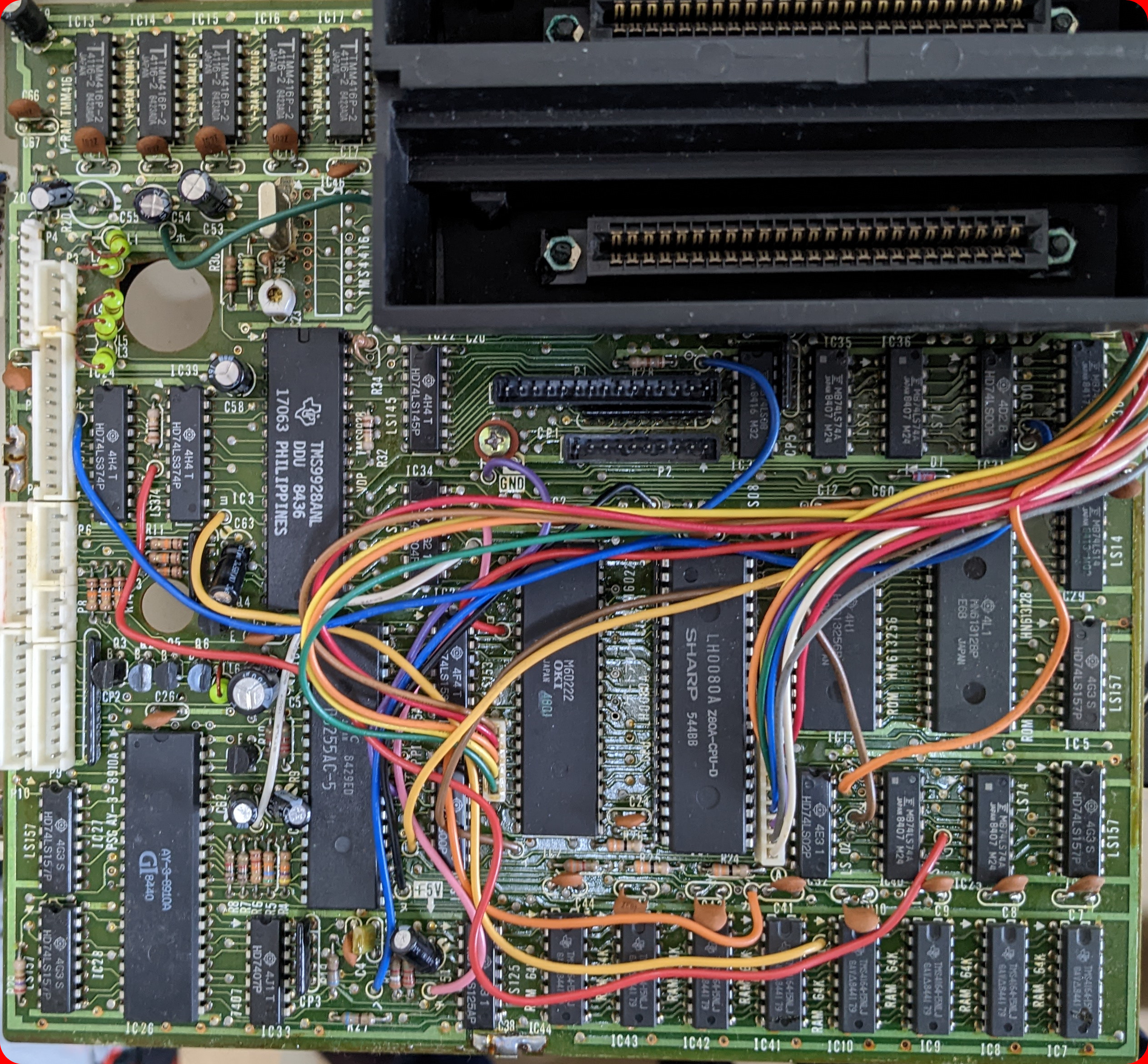
There was no oscillating signal on the VDP’s XTAL 1/XTAL 2 (pins 63 and 64). Unlike all other retro computers I have seen thus far, this signal is generated by a 74LS628 IC on the analog board. However, it took me a while to figure out that that is the case. In fact, I did not realize this until I decided to take a look at the service manual for a very similar computer, the Sony HB-G900P, linked from the bottom of the page at https://www.msx.org/wiki/Sony_HB-G900P. This service manual mentioned the 74LS628 IC, and how to adjust it.
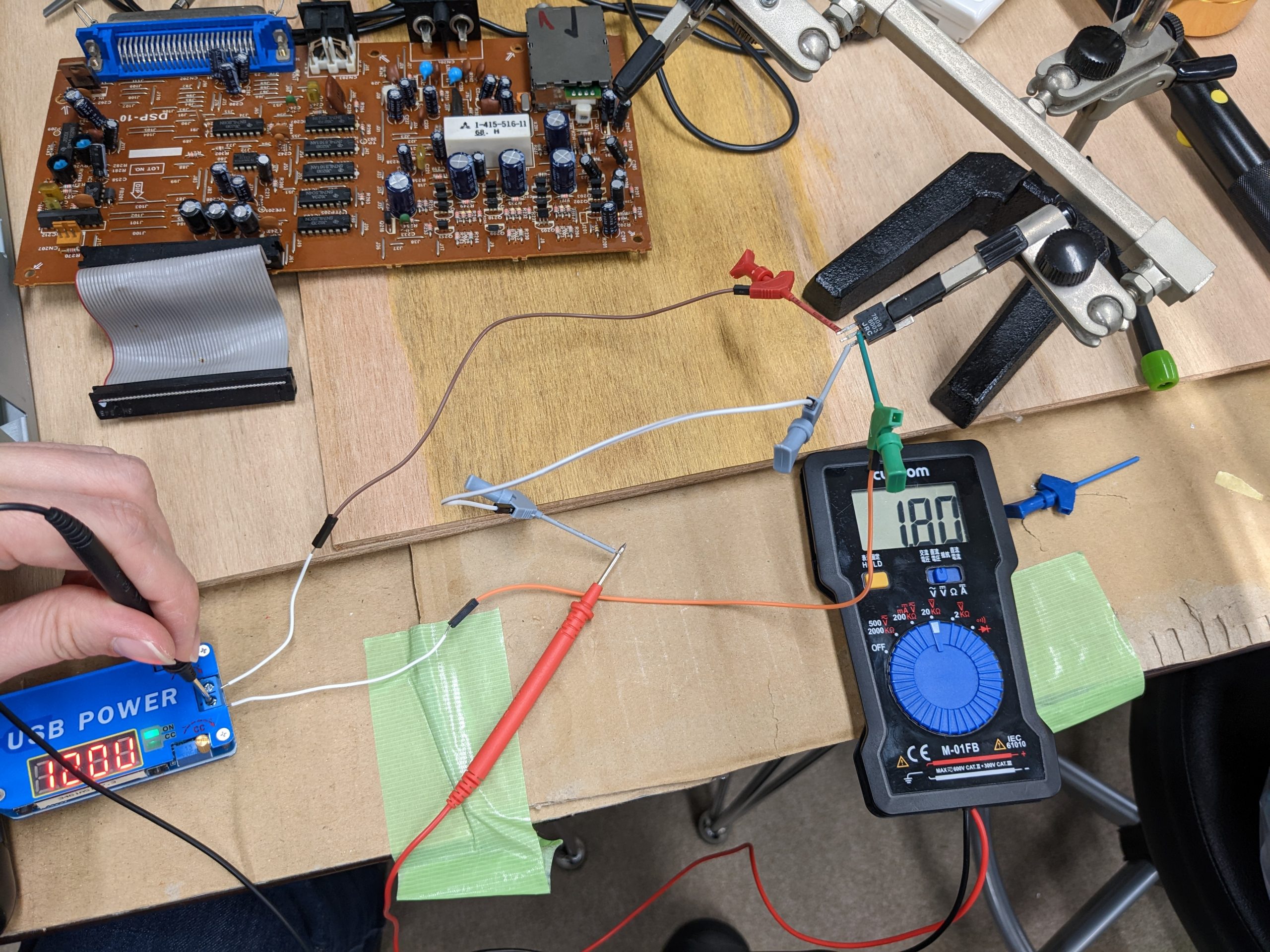
However, this IC wasn’t even getting 5V, and it turns out that there’s a 5V supply separate from the 5V supply used to supply power to all the other logic chips on the two boards. The IC gets its 5V through two linear regulators, first a 7809 turning 12V into 9V, and a 7805 turning 9V into 5V. The 7809 was broken with the following failure mode: up to about 10V, it output input minus 1-2V, and beyond that, it output 0.5-2V.
Input: 10V (display is inaccurate, actually closer to 9.7V), output: 8.93VInput: 12V (actually 11.8V), output: 1.8V.Running the machine with the regulator removed and my trusty USB power supply (set to 9V, display is imprecise) attached instead.
Replacing the 7809 fixed the machine. However, it appears that the floppy drives may be somewhat broken. I’ll look into that soon.
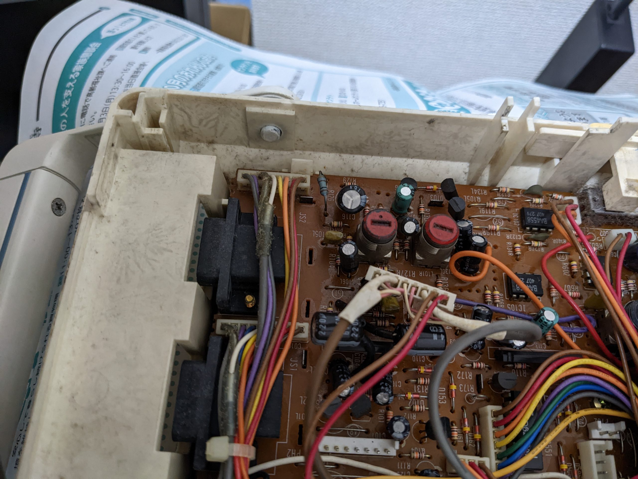
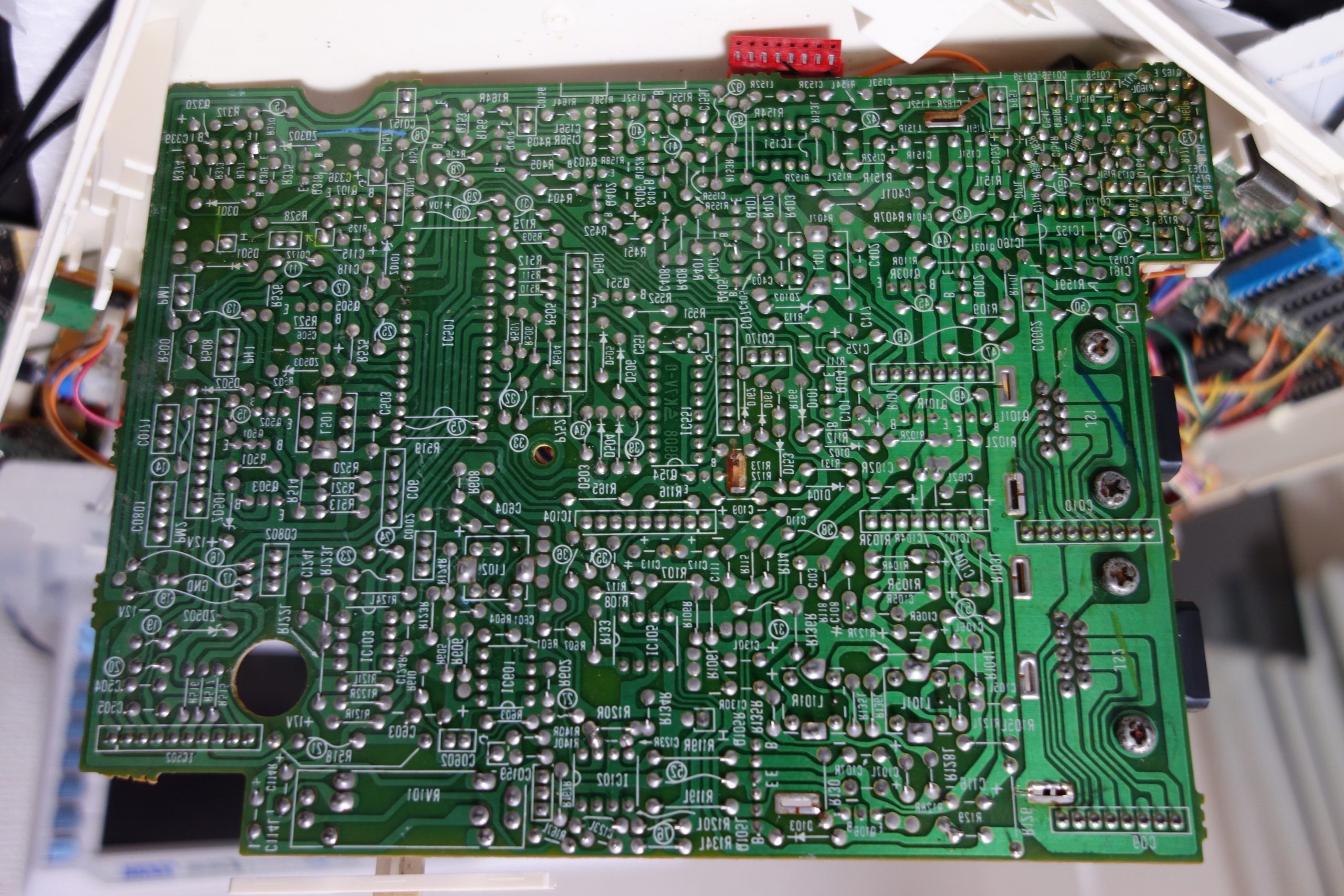
Just some colored traces on a board pic with RF shield removed:
(Grey: GND Pink: 12V Violet: 5V I do not really remember the rest…)
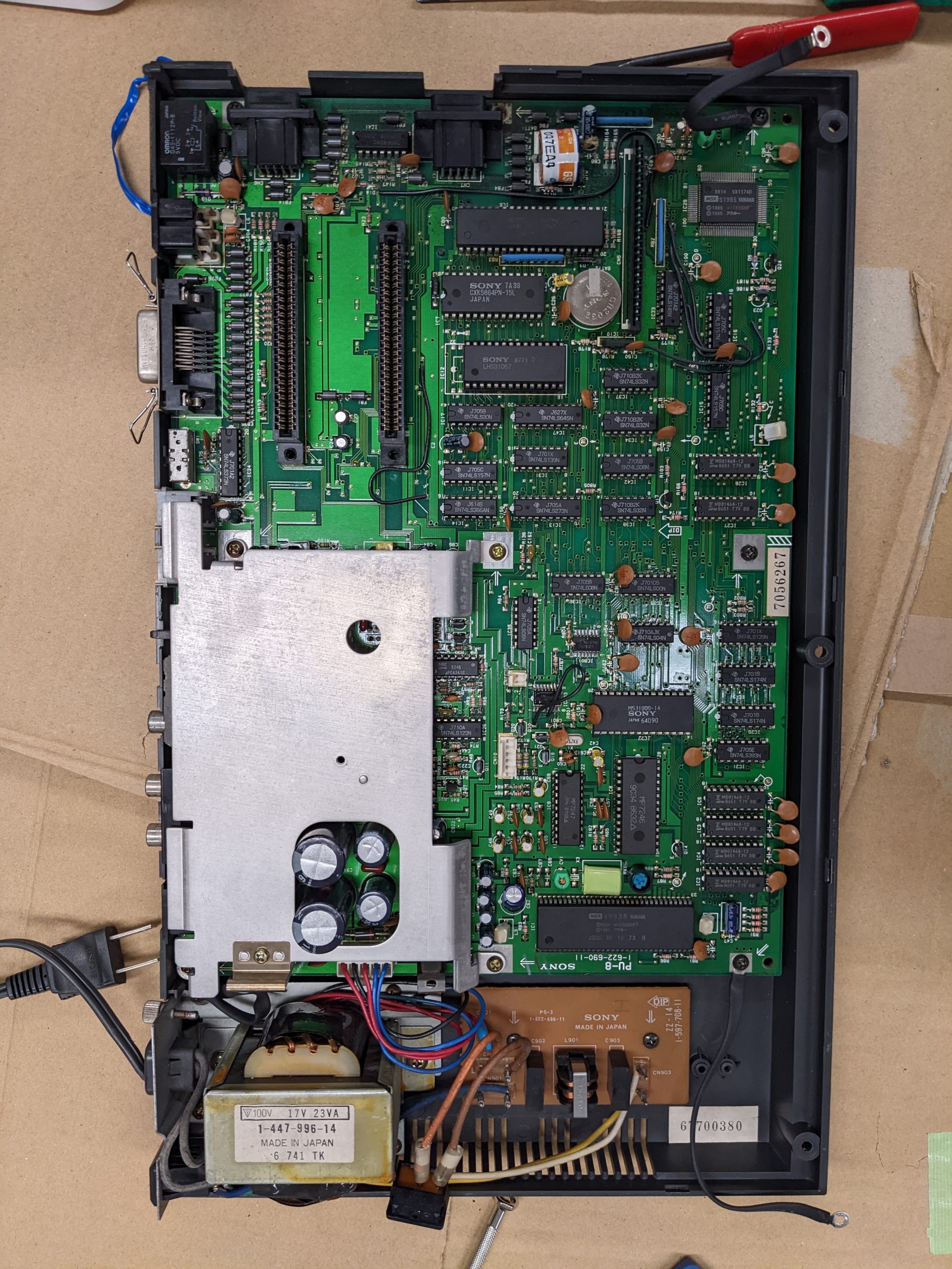
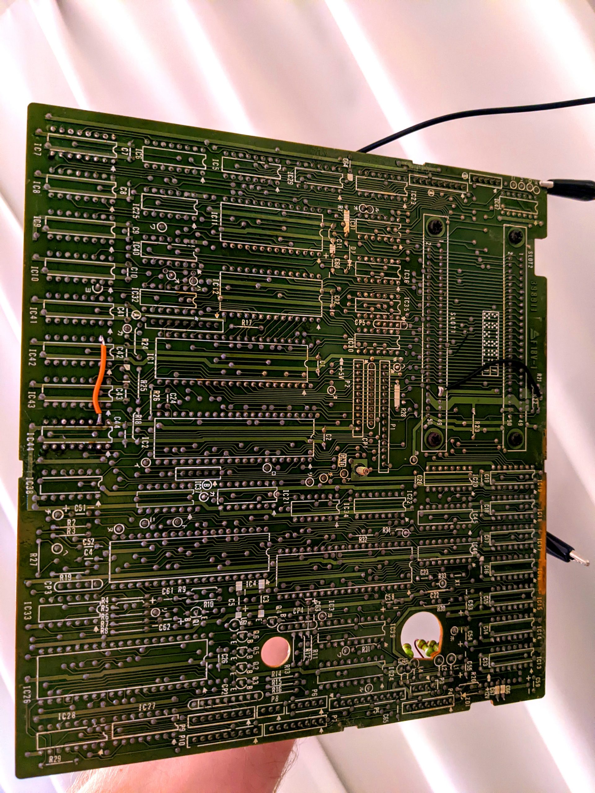
Logic board:
(This is the backside of the logic board, left side is bottom side.)Logic board, front side. This is actually a different H2’s board (with highly readable print on the chips), but should be the same.
In this article, we’ll create a short memory test for use on MSX/MSX2 machines to check the lower 32 KB of RAM. Why only the lower 32 KB of RAM? Because you can check the higher 32 KB using pure BASIC PEEKs and POKEs, and generally software won’t run if the higher 32 KB has defects. (Many games may still run even with defects in the lower 32 KB.)
It’s useful to have a test that can be run from BASIC and that can be typed into the machine in a couple minutes.
MSX bank switching
The MSX has a CPU that can only address 65536 addresses, but can have 64 KB of RAM and at least 16 KB of ROM. In a previous article, I mentioned that that is probably handled by copying ROM into RAM, but that is wrong. Instead, there is a chip that has a couple registers and enables/disables ROM/RAM chips based on the value of one of those registers.
On some MSX machines (but not the ones I tried) you may be able to read out that register from BASIC:
print inb(&ha8)
Summary: ROM/RAM can be switched in/out in 16 KB chunks, 0x0000-0x3fff, 0x4000-0x7fff, 0x8000-0xbfff, 0xc000-0xffff. There are four choices possible for each chunk. The register is 8 bits: 2 bits for the first chunk, 2 bits for the second chunk, etc.
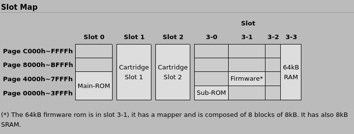
There is another register (or rather another register for each slot) though, and it’s often used on MSX2 machines. This register is accessed in memory space, not I/O space. (Memory address 65535, requires that the correct slot be selected in the 0xc000-0xffff chunk.) This register gives us another four choices to select a different ROM/RAM for each choice already made. In other words, we have 4 pages (chunks), 4 slots (ROM/RAM choices), and for each slot, another 4 “subslots” (ROM/RAM choices). If you didn’t 100% understand that, don’t worry, I don’t actually think it’s comprehensible the way I wrote it. But you may still be able to follow the discussion below.
When we start BASIC on a 64 KB machine, we’ll probably have the lower 32 KB mapped to some kind of ROM, and the upper 32 KB mapped to RAM. BASIC then lets us use about 28 KB of that RAM and reserves about 4 KB for its own purposes, or so I assume. (The firmware selects the right slots and subslots to make this work for the machine in question, and the required numbers are different depending on the machine’s configuration. Also remember that there are RAM extension cartridges. During the boot phase, the firmware actively probes the 16 KB chunks to see if something is RAM or not. BTW, if the RAM is sufficiently bad, it won’t detect it as RAM at all and you’ll never see the boot screen.)
BASIC runs from ROM. If we disable that ROM (the “slot” containing the ROM) and instead enable RAM (the “slot” containing the RAM) on that “page” (chunk), we’ll be pulling the carpet from under BASIC’s feet. So if we run a command like this in BASIC:
out &ha8,0
The system will freeze immediately. So instead, we’ll be writing our memory test in assembler and poke it into memory, and then execute it.
We’ll be using a total of 9 instructions in our memory test program. Even if you have never seen Z80 assembly code, the following is almost all you need to know: “di” disables interrupts, just in case. “ei” re-enables interrupts. “ret” returns from our code, i.e., we’ll go back to BASIC. “ld” loads some 8-bit value to destination, from source. Numbers in (parentheses) are like dereference in C. (Except for in/out, you always uses parentheses there.) “cp” is compare argument with register “a”. (Some instructions require the use of register “a”.) “jp” is jump. “jp z,…” is “jump if equal”. “z” meaning, “if zero flag is set”.
Let’s first take a look at a short program that switches slots, undos the switch, and returns. It looks like this:
org 0c000h

di ; disable interrupts
ld a,0ffh ; put "255" in register "a" (the correct value depends on your machine!)
out (0a8h),a ; enable IO write, and put "0xa8" on the address bus and contents of register "a" on the data bus
;subslot
ld hl,0ffffh ; put "65535" in register "hl"
ld (hl),0ffh ; write "255" into *hl, i.e. into address 65535 (the correct value to write depends on your machine!)
;/subslot


; now undo everything:

ld a,0f0h ; put "240" in register "a" (the correct value depends on your machine!)
out (0a8h),a ; enable IO write, and put "0xa8" on the address bus and contents of register "a" (i.e., 240) on the data bus
;subslot
ld hl,0ffffh ; put "65535" in register "hl"
ld (hl),0f0h ; write "0" into *hl, i.e. into address 65535 (the correct value to write depends on your machine!)
;/subslot
ei ; enable interrupts
ret ; return to caller (BASIC)
This code can be assembled using “z80asm”, which is available in Debian’s repositories at least. z80asm outputs a file called “a.bin”. We can convert that file to unsigned 8-bit integers for use on BASIC data lines using od -t u1 a.bin.
Anyway, now we just need to add some code between the two snippets above. We want code that writes to memory addresses and then compares what was written. Here’s the annotated assembly code to do that:
ld hl,00h ; put 0 in register "hl"
write: ; this is a label that we can use in "jp" (jump) instructions
ld (hl),0ffh ; put 255 in *hl, i.e. address 0
inc hl ; increment hl register
ld a,h ; put high byte of "hl" register into "a" register
cp 080h ; check if the "a" register contains 0x80
jp z,done_writing ; if yes, that means we have incremented the hl register a bunch of times and it's time to go check if what we wrote earlier is still there (i.e. we've written 255 into 0x0000 to 0x7fff)
jp write ; if we reach this instruction, that means that the previous instruction didn't perform its conditional jump. this instruction jumps back to the instruction at the "write" label (ld (hl),0ffh). i.e., we haven't reached 0x8000 yet.

done_writing: ; this is a label
ld hl,00h ; put 0 in register "hl"
compare: ; this is a label
ld a,0ffh ; put 255 in register "a"
cp (hl) ; compare contents of register "a" with contents of *hl, i.e. memory address 0
jp nz,bad ; we put 255 in there earlier but this address contains something else now, that means we have bad memory
inc hl ; if we reach this instruction, that means that the previous instruction didn't perform its conditional jump. increment hl register
ld a,h ; put high byte of "hl" register into "a" register
cp 0c0h ; check if the "a" register contains 0xc0
jp z,done ; if yes, that means we have incremented the hl register a bunch of times and it's time to go home
jp compare ; if we reach this instruction, that means that the previous instruction didn't perform its conditional jump. this instruction jumps back to the instruction at the "compare" label (ld a,0ffh)

bad:
...

done:
...
Finding the correct values for I/O port A8 and memory port 65535
To make the assembled code work on your MSX, you will most likely have to change the values to be written into the A8 I/O register and the values to be written into address 65535 to select the correct sub-slot.
We want to access RAM, and it’s at slot 3, subslot 3. In BASIC, I get the following output:
?peek(65535)
15
This output is inverted. 15 is 0b00001111 in binary, but we should read this as 0b11110000. The lowest two bits specify the subslot for the 0x0000-0x3fff block. The subslot is set to 0b00, i.e. 0 here. Same for 0x4000-0x7fff. On page 0x8000-0xbfff, we see that subslot 0b11, i.e., 3 is selected. Same for 0xc000-0xffff. This is as expected — the above table from the MSX wiki page specifies that all RAM is at subslot 3 (of slot 3).
If we want the lower pages to point to RAM, we not only have to set the A8 register to 3 (because all the RAM is at slot 3), we also have to select subslot 3.
I.e., to set the subslots for all four 16 KB chunks (“pages”) to use RAM, which is at slot 3 subslot 3, we have to write 0b11111111. To revert this, we have to write 0b11110000 (our peek showed 15 (0b00001111) at memory address 65535, but this is inverted, hence 0b11110000).
Customizing the memory test
In the above code, we write 0xff to all addresses, and then later check if 0xff is still there. However, one very common type of memory fault is “stuck bits”, where memory bits are always stuck at 1, even if we’d written 0. In order to test that, I recommend that you change “ld (hl),0ffh” and “ld a,0ffh” under the “write” and “compare” labels to different values.
We also have to think about what to do if we have encountered bad memory. One easy thing we can do is generate an audible click. (May be somewhat faint.) Here’s the code to do that:
bad:
ld a,15
out (0abh),a
ld a,14
out (0abh),a
ld a,15
Writing 15 and then 14 to 0xAB produces a click. You can do this in BASIC too:
out &hab,15:out &hab,14
Alternatively, we could write the memory address that contained something unexpected into some memory location, for example like this:
ld de,0c100h ; memory address to write to
ld a,h
ld (de),a
inc de
ld a,l
ld (de),a
This would write the significant byte of the failed address to 0xc100 and the insignificant byte to 0xc101.
Putting it all together
Here’s the assembly code for the whole test:
org 0c000h

di
ld a,0ffh
out (0a8h),a
;subslot
ld hl,0ffffh
ld (hl),0ffh
;/subslot
ld hl,00h
write:
ld (hl),0
; ld (hl),l ; alternative code, fills RAM with 0x00-0xff, 0x00-0xff, ...
; nop
inc hl
ld a,h
cp 080h
jp z,done_writing
jp write

done_writing:
ld hl,00h
compare:
ld a,0
; ld a,l ; alternative code, see above
; nop
cp (hl)
jp nz,bad
inc hl
ld a,h
cp 080h
jp z,done
jp compare

bad: ; audible click version
ld a,15
out (0abh),a
ld a,14
out (0abh),a
ld a,15

done:
ld a,0f0h
out (0a8h),a
;subslot
ld hl,0ffffh
ld (hl),0f0h
;/subslot
ei
ret
And here’s the short BASIC loader:
10 i=49152
20 read j
30 if j=-1 then goto 80
40 poke i,j
50 i=i+1
60 goto 20
70 data 243,62,255,211,168,33,255,255,54,255,33,0,0,54,255,35,124,254,128,202,25,192,195,13,192,33,0,0,62,255,190,194,44,192,35,124,254,128,202,54,192,195,28,192,62,16,211,171,62,14,211,171,62,15,62,240,211,168,33,255,255,54,240,251,201,-1
80 def usr1=49152

run
Ok.
x=usr1(0)
Ok.
If you get “Ok.” after “x=usr1(0)”, the machine hasn’t crashed (which means your slot and subslot selections were correct). If you heard a click, your memory is probably defective.
The click may be hard to hear, so maybe try running “x=usr1(0)” in a loop:
Make the software easy to use by getting rid of advanced features? Make the software featureful but harder to use?
Make the software comfortable to develop for but invest a lot of time setting up frameworks and maintaining them? Or make the software a bit less comfortable to work on, but avoid spending a bunch of learning/maintaining the frameworks?
Well, it’s all up to you, and I have a strong belief that people shouldn’t have strong beliefs about this! Er, okay.
Let’s say you want to add a couple tests (b.c) for individual static functions hidden in a .c file somewhere (a.c). Well, you can’t access those static functions from other .c files. Put the tests in the .c file? Some people would call it ugly. You could also write a script that concatenates the source file and test file and compiles that instead! Bit messy. You can’t have multiple main() functions, etc. But have you ever considered making the “static” keyword disappear using the C preprocessor? It works! And it can be messy too because it’ll make your static variable non-static. Great. But there are cases where that doesn’t matter, especially when we’re just trying to run some unit tests. Here’s a minimum example:
$ cc -o foo a.c b.c
/usr/bin/ld: /tmp/ccpspoxC.o: in function `main':
b.c:(.text+0x15): undefined reference to `a'
collect2: error: ld returned 1 exit status
$
It doesn’t work, duh. Because a() is static.
And now we’re going to make static disappear and it’ll work, so you can put all your tests in what we called b.c:
$ cc -Dstatic= -o foo a.c b.c
$ # no errors
If you don’t have control over the code base you are working on but still want some quick tests, this hack may be useful.