In a previous post, we did some warmups — playing MSX games using a fake PS3 controller. In this post, we’ll be using GP2040-CE to control a Nintendo Switch. (No analog stick support implemented at the moment, but it wouldn’t be hard.) At the time of writing, most of the code to do this is already there! And I’m sure there will be support for USB-HID controllers in no time, so this post will probably be outdated soon. Update: Analog is implemented too, and the diff below has been updated.
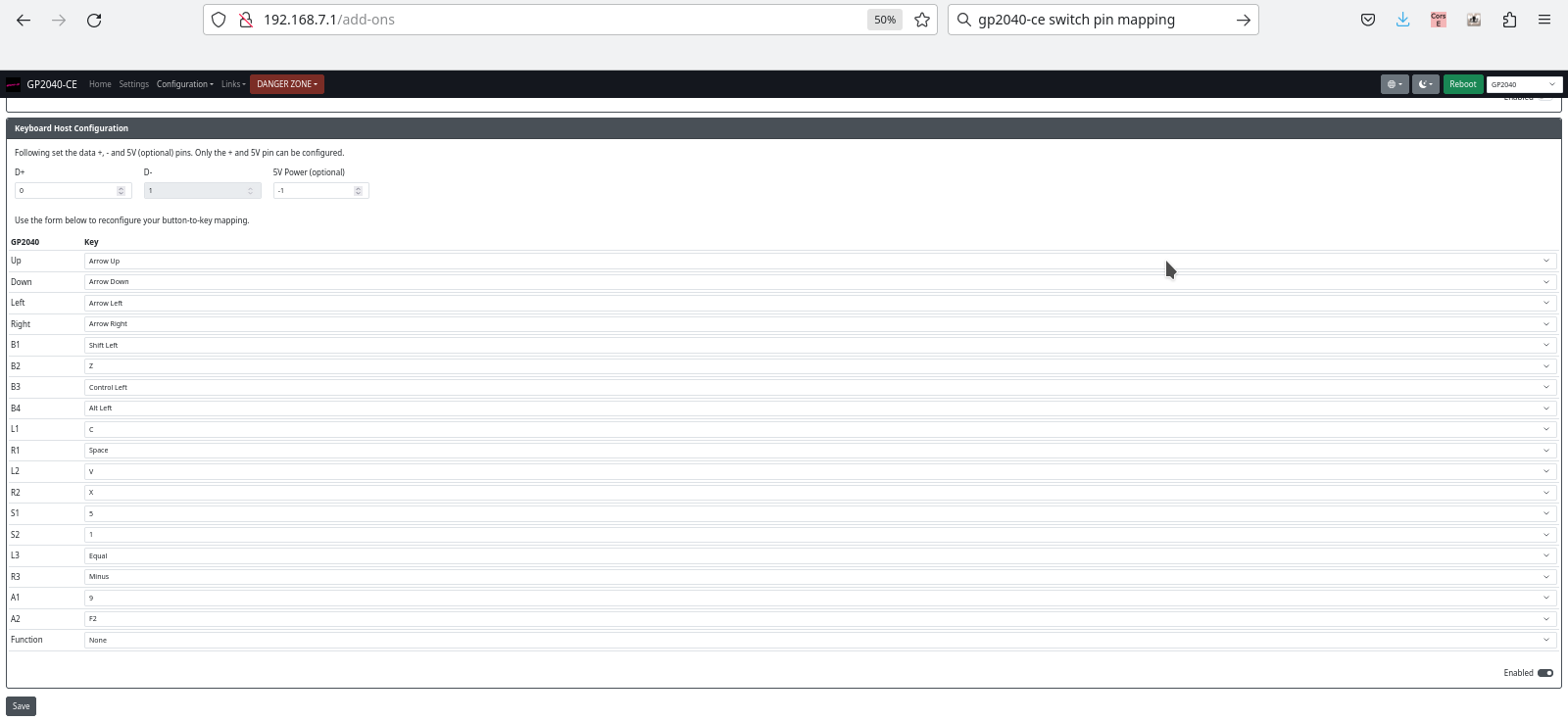
Anyway, you just need to put GP2040-CE on your Pico and get into the web configuration. In add-ons, you enable keyboard support, and then set up the “Keyboard Host Configuration”, which looks like this:
GP2040-CE keyboard mapping and other configuration
Then you can connect a generic USB keyboard to the Raspberry Pi Pico, and connect the Pico to the Nintendo Switch. (For electrical reasons, I do not recommend setting a pin for 5V power here, and just putting the host USB +5 on the VBUS pin of the Pico.)
Things that could come in handy: Breadboard, Raspberry Pi Pico, USB port that can be connected to one of the Pico’s GPIO pins
If everything works and you can control Sonic using your keyboard, great, you can move on to the next step! If it didn’t work, it probably won’t magically get better from here on out, so make sure to check those connections. The green/white wires can be D+/D- or D-/D+!
Now we’ll perform a small modification to the existing code. I’m basing my work on commit 961c49d5b969ee749ae17bd4cbb2f0bad2380e71. Beware, this may or may not work with your controller. I’d recommend taking a look at the above-mentioned previous post where we modify a Pico-PIO-USB example and to check if your controller behaves the same way. I have only two controllers to test with, and I only tested with one! Anyway, here’s the diff:
Good luck. Miraculously, everything worked perfectly for me. The keyboard worked immediately, the above code modification worked immediately without having to do any debugging, and I’ve gotta say, my fake PS3 controller feels quite okay! (Note that you will have to press the PlayStation button after connecting your PS3 controller.)
Symptoms on real PS3: probably “crazy behavior”, I didn’t actually test on a real PS3. Symptoms when connected to a computer with a program open that displays the gamepad status: random button presses, button “flickering”, buttons going on and off randomly, possibly depending on how the controller is held.
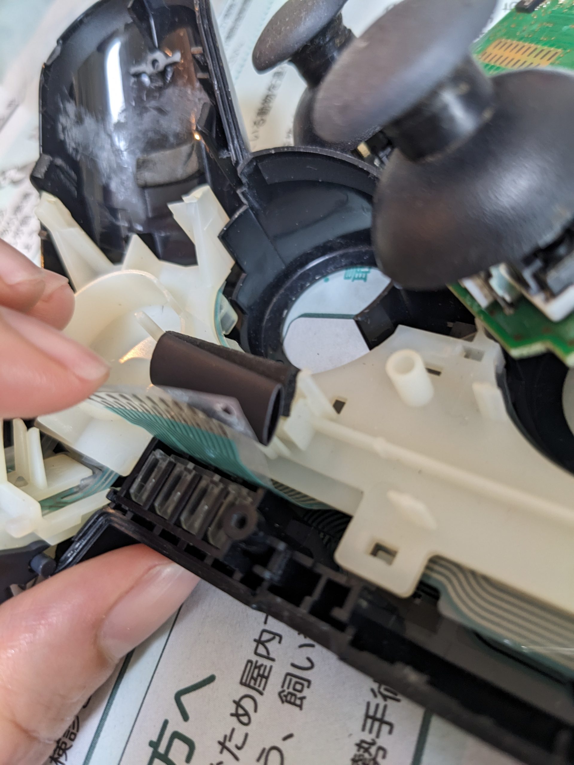
Cause in my case: rubber cushion is worn out, and/or physical damage to the controller’s case and/or loss of one of the screws. The rubber cushion sits on a piece of plastic, and a flex cable is sandwiched between the rubber cushion and the PCB. If the rubber cushion loses some of its original height, for example due to wear, or if one of the controller’s screws are lost and the PCB isn’t pressed as hard against the rubber cushion as it used to, buttons will randomly appear pressed or unpressed. (When there is absolutely no connection between the flex cable and the PCB, all buttons will appear pressed. When the connection is flaky, buttons may appear pressed all the time, or go on and off.)
Fix: adding a little height to the cushion fixed the problem for me.
In this pic, I’m holding the flex cable with one of my fingers. The tube (it’s a piece of heat shrink, actually) is what I added to improve contact between the flex cable and PCB. The original rubber is still there.
There is very little code that I wrote myself in this project, but it’s the first time I’m looking at USB-HID on the protocol level and the end result is something mildly useful. So possibly worth a post? (Note: code is at the bottom of this post.)
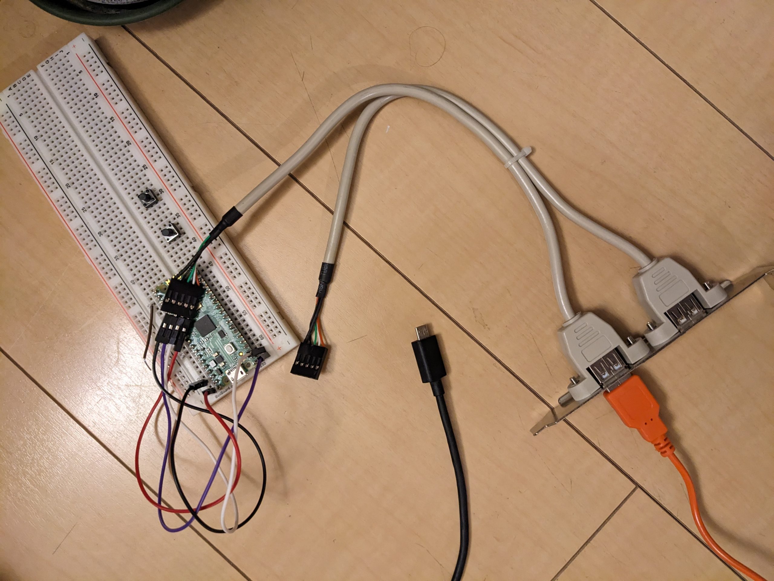
All we’ll be doing here is modify an example from https://github.com/sekigon-gonnoc/Pico-PIO-USB, namely, the capture_hid_report example. You’ll need a good way to connect a USB-A port to your Raspberry Pi Pico. I’m using an old piece of hardware that was meant for use in desktop PCs to add USB ports on the back, internally connected to motherboard headers. (In the demo we’re using, USB D+ and D- are GPIO pins 0 and 1, respectively.)
Once you have your Pico flashed, open a serial terminal, and then connect a USB-HID gamepad. I’m using a fake PS3 controller. It looks very similar to a Sony PS3 controller but bears a “P3” mark instead of the PlayStation logo on the middle button. (I don’t know if it works with a real PS3.) (I’m leaving out the wiring details here, but it’s all exactly as explained in the README.md in the repo.) I get the following messages when I plug in my controller. The “EP 0x81” messages are sent continuously.
You can also use Linux tools such as usbhid-dump to get reports, but for some reason they look quite different from what I get here. Don’t know if the driver is doing something (odd, or not so odd) or if the Pico is doing something odd. (It’s quite likely that there’s a driver in Linux that configures the controller automatically. On the Pico you have to press the P3 button every time after plugging in, on Linux it lights up the first player LED immediately.)
This doesn’t look quite exactly the same as the examples in the tutorial. Below is my understanding, which may not be 100% correct, but makes sense to me at least. Let’s look at some output lines from the capture_hid_report example. The first line was:
First of all, all lines start with “054c:0268 EP 0x81”. That’s just added by the example code. Let’s go through the remaining numbers in the line (actually, just the bolded ones) and see how they relate to the descriptor we saw earlier.
01: report ID, same as the report ID defined in the descriptor.
00: this is the entire report that was described in the following extract from the descriptor, exactly 1 byte (8 bits):
This is actually two reports. One is 19 bits, the other is 13 bits. Together that’s exactly 32 bits. (This is similar to the three mouse buttons example in the tutorial, where we only have three buttons and therefore want to pad this to 8 bits.) Here, we have 19 buttons (though the controller only sports 16 physical buttons, unless I’m much mistaken), each of which is 1 bit, i.e., either pressed, or not. The remaining 13 bits are just to pad the report to make it easier to handle on the software side, or perhaps the padding is required somehow. (Looks like it is on Windows at least: https://stackoverflow.com/questions/65846159/usb-hid-report-descriptor-multiple-reports.)
And indeed, these four bytes (well, the first 19, er, 16 bits) do change when buttons are pressed. This is basically all we need to figure out how to use this controller with an MSX. We just need to figure out which button is responsible for which bit in the third and fourth bytes. (Unless we also wanted to translate analog stick input.)
What about the rest of the bytes? I don’t know how they relate to our descriptor above, but pressing buttons and moving the analog sticks makes it pretty obvious what they mean. We can see that the analog sticks are two bytes each, and there’s another byte for each button, and the value that comes up depends on how hard the button was pressed. I never knew that the △□○☓ buttons were pressure-sensitive on the PS3! Anyway, perhaps it’s possible that our descriptor is incomplete, as the frame they are transmitted in is limited to 64 (or maybe 63?) bytes?
So without going into any hardware details yet, here’s how we could modify the example code to translate our button presses to electric pulses on a GPIO pin. Here’s the part of the code that we’ll replace:
if (len > 0) {
  printf("%04x:%04x EP 0x%02x:\t", device->vid, device->pid,
        ep->ep_num);
  for (int i = 0; i < len; i++) {
    printf("%02x ", temp[i]);
  }
  printf("\n");
}
And here’s some of the code we could maybe replace the above block with. Note that this doesn’t actually consider the hardware details of the actual MSX interface yet, it’s just an example, so don’t copy this code. The actual code is in the last section of this blog post.
if (len > 0) {
  if (temp[0] == GAMEPAD_REPORT_ID) { // GAMEPAD_REPORT_ID is 1 in our case
    uint16_t button_state = (temp[2] << 8) | temp[3];
    if (button_state & BUTTON_UP) {
      gpio_put(BUTTON_UP_PIN, 1);
    } else {
      gpio_put(BUTTON_UP_PIN, 0);
    }
    if (button_state & BUTTON_DOWN) {
...
  }
}
My controller’s button mappings are as follows:
#define BUTTON_UP 0x1000
#define BUTTON_DOWN 0x4000
#define BUTTON_LEFT 0x8000
#define BUTTON_RIGHT 0x2000
#define BUTTON_A 0x40 // X or O, can't remember
#define BUTTON_B 0x20 // X or O, can't remember
MSX interface
Good news: the MSX joystick ports come with 5V and GND pins. According to https://www.msx.org/wiki/General_Purpose_port, we can draw up to 50 mA from these pins. Is that enough for the Pico and a controller? It is for mine! According to my measurements, the Pico + fake PS3 controller together draw about 40 mA. (Instrument’s display precision is 10 mA, so it could be up to 45 mA, or more if the instrument is inaccurate.) Note that many modern controllers (including real PS3 controllers) contain a battery, and will attempt to charge it. That will most likely take the current way above 50 mA. (Note: I don’t think that drawing slightly more than 50 mA would be a huge problem at least on my MSX, which I’ve disassembled and reassembled a couple times.)
Slightly bad news (1): pressing buttons on MSX joysticks connects pins to pin 8, which is not GND. Pin 8 is “strobe” and can be GND or 5V. (Button pins are normally pulled high.)
Slightly bad news (2): on the MSX side, the joystick ports are actually GPIO ports and can be configured for both input (normal) and output! We don’t want the Pico to output when the MSX’s PSG is outputting too!
1: addressing this in software might be possible, albeit with a (very) short time lag. I don’t really know anything about this feature and have no easy way to test a software-based solution with MSX software that actually uses this feature. 2: I don’t think regular MSX joysticks worry about this. Some MSX systems may have safeguards in place.
Some measurements and wiring details
Using my multimeter’s rarely used ammeter mode, with the probes between STROBE and any button pin, I see a current of ~0.7 mA. (Two button pins, and the ammeter shows 1.5 mA. It probably goes up linearly the more buttons you press.) That’s quite a lot by modern standards!
On my MSX, there are two 74LS157 chips that implement joystick selection. The 74LS157’s outputs are directly connected to the PSG’s inputs. (Only one joystick’s state is visible to software at a time; a PSG register change is required to switch to the other one.) If we change the PSG’s I/O port’s direction, I think we’ll be pitting the 74LS157’s outputs against the PSG’s outputs. Doesn’t sound so great, eh. Except, the 74LS157 has an \ENABLE pin! When the \ENABLE pin on a 74LS157 is disabled, the outputs will be high-Z, potentially allowing a signal coming from the PSG to make its way somewhere. Is there such functionality on the MB-H2? Answer after some probing: no. \ENABLE on these two chips is tied to GND.
While most button pins have 10K pull-up resistors (some seem to have 3.3K pull-up resistors), the STROBE pins are connected directly to PSG pins 8 and 9.
Deciding how to hook up the Pico to the joystick port
In real joysticks, when you press a button, you short the STROBE pin to the button pin, and STROBE can be HIGH or LOW. (When STROBE is HIGH, we short HIGH to HIGH, and nothing happens. Since on my MSX, as discussed above, the button pins are connected to 74LS157 inputs, they should always be pulled high, and never go low during device operation.) In real joysticks, when nothing is pressed, there is no connection, period. So that’s more like a tri-state affair, so instead of producing a HIGH level when nothing is pressed, we should set our Pico’s GPIO to high-Z (which we can do by setting it to INPUT).
Armed with the measurements above, I think we can hook up the Pico directly (let’s ignore 5V vs 3.3V for now), producing a LOW level when a button is pressed. We’ll have the Pico’s GPIO pin sink a little bit of current, but not too much. Even if all 6 buttons are pressed, the Pico shouldn’t sink more than around 4.5 mA across multiple pins. That’s okay, really. Even if we decided to make the Pico interface with two controllers, that’s still comfortably under our limit.
Now we could start thinking about reducing the 5V on the button pins to 3.3V on the Pico’s GPIO pins. But according to many accounts, 5V is okay if it’s sufficiently current-limited, which it is, in our case. So let’s ignore this for now.
Other MSX machines
(I will probably expand this section at some point.)
YIS-503
The YIS-503 (schematics, look at the circuits near the JOY1 and JOY2 connectors on the left) has 22K pull-up resistors and an MSX Engine. I doubt that MSX Engine chips (which have the PSG integrated) can be configured to destruct themselves.
10k pull-up resistors. The rest of the wiring looks exactly like on the Hitachi MB-H2 as far as I can tell.
So does it actually work?
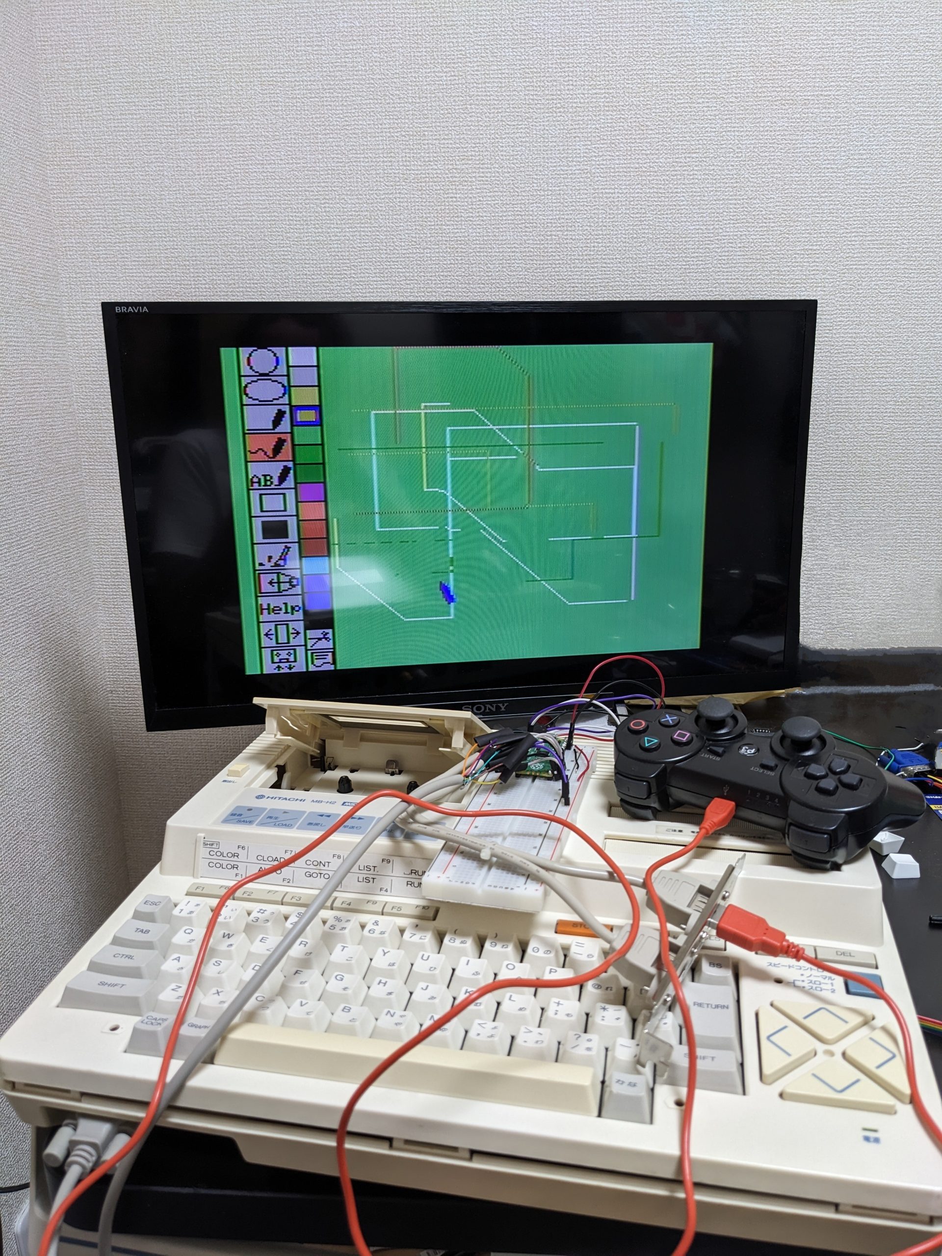
Yes. Here’s a pic of my trusty Hitachi MB-H2 MSX running its built-in sketch program, controlled through the fake PS3 controller. (Sorry, the computer’s still open from the probing I did earlier.)
The USB port is a PC part that I found at my local Hard Off. The RS232 cable is also from Hard Off. In fact, the fake PS3 controller is also from Hard Off! The USB cable is from my own cable collection.
Totally off-topic, but there’s a spot in this pic that has been cleaned up using my Pixel phone’s magic eraser. Can you see where it is? (I didn’t touch it up in an image editor afterwards.)
Pacman <3
Problems
Plugging our contraption into the joystick port while the MSX is running crashes the machine! The screen goes very slightly dark for a split second too. Probably in-rush current. I’m pretty sure I blew my multimeter’s (200 mA) fuse trying to measure the current. Laff. (Having the controller already plugged in before powering on the computer works fine.)
Source code
Replace your Pico-PIO-USB/examples/capture_hid_report.c with the following code, (re-)make, flash, and you’re set. (I’m basing my modifications on git commit d00a10a8c425d0d40f81b87169102944b01f3bb3.)
#include <stdio.h>
#include <string.h>

#include "pico/stdlib.h"
#include "pico/multicore.h"
#include "pico/bootrom.h"

#include "pio_usb.h"

#define GAMEPAD_REPORT_ID 1

// 0x1: L2
// 0x2: R2
// 0x4: L1
// 0x8: R1
// 0x10: Triangle
// 0x20: Circle
// 0x40: X
// 0x80: Square?
// 0x100: ?
// 0x200: ?
// 0x400: R3
// 0x800: Start
// 0x1000: Up
// 0x2000: Right
// 0x4000: Down?
// 0x8000: Left?

#define BUTTON_UP 0x1000
#define BUTTON_DOWN 0x4000
#define BUTTON_LEFT 0x8000
#define BUTTON_RIGHT 0x2000
#define BUTTON_A 0x20
#define BUTTON_B 0x40
#define BUTTON_A_ALT 0x10
#define BUTTON_B_ALT 0x80

#define BUTTON_UP_PIN 16
#define BUTTON_DOWN_PIN 17
#define BUTTON_LEFT_PIN 18
#define BUTTON_RIGHT_PIN 19
#define BUTTON_A_PIN 20
#define BUTTON_B_PIN 21

static usb_device_t *usb_device = NULL;

void core1_main() {
  sleep_ms(10);

  // To run USB SOF interrupt in core1, create alarm pool in core1.
  static pio_usb_configuration_t config = PIO_USB_DEFAULT_CONFIG;
  config.alarm_pool = (void*)alarm_pool_create(2, 1);
  usb_device = pio_usb_host_init(&config);

  //// Call pio_usb_host_add_port to use multi port
  // const uint8_t pin_dp2 = 8;
  // pio_usb_host_add_port(pin_dp2);

  while (true) {
    pio_usb_host_task();
  }
}

static void gpio_setup()
{
  gpio_init(BUTTON_UP_PIN);
  gpio_init(BUTTON_DOWN_PIN);
  gpio_init(BUTTON_LEFT_PIN);
  gpio_init(BUTTON_RIGHT_PIN);
  gpio_init(BUTTON_A_PIN);
  gpio_init(BUTTON_B_PIN);

  gpio_set_dir(BUTTON_UP_PIN, GPIO_IN);
  gpio_set_dir(BUTTON_DOWN_PIN, GPIO_IN);
  gpio_set_dir(BUTTON_LEFT_PIN, GPIO_IN);
  gpio_set_dir(BUTTON_RIGHT_PIN, GPIO_IN);
  gpio_set_dir(BUTTON_A_PIN, GPIO_IN);
  gpio_set_dir(BUTTON_B_PIN, GPIO_IN);

  gpio_put(BUTTON_UP_PIN, 0);
  gpio_put(BUTTON_DOWN_PIN, 0);
  gpio_put(BUTTON_LEFT_PIN, 0);
  gpio_put(BUTTON_RIGHT_PIN, 0);
  gpio_put(BUTTON_A_PIN, 0);
  gpio_put(BUTTON_B_PIN, 0);
}

int main() {
  // default 125MHz is not appropreate. Sysclock should be multiple of 12MHz.
  set_sys_clock_khz(120000, true);

  stdio_init_all();
  printf("hello!");

  sleep_ms(10);

  multicore_reset_core1();
  // all USB task run in core1
  multicore_launch_core1(core1_main);

  gpio_setup();

  while (true) {
    if (usb_device != NULL) {
      for (int dev_idx = 0; dev_idx < PIO_USB_DEVICE_CNT; dev_idx++) {
        usb_device_t *device = &usb_device[dev_idx];
        if (!device->connected) {
          continue;
        }

        // Print received packet to EPs
        for (int ep_idx = 0; ep_idx < PIO_USB_DEV_EP_CNT; ep_idx++) {
          endpoint_t *ep = pio_usb_get_endpoint(device, ep_idx);

          if (ep == NULL) {
            break;
          }

          uint8_t temp[64];
          int len = pio_usb_get_in_data(ep, temp, sizeof(temp));

          if (len > 0) {
            if (temp[0] == GAMEPAD_REPORT_ID) {
              uint16_t button_state = temp[2] << 8 | temp[3];
              if (button_state & BUTTON_UP) {
                gpio_put(BUTTON_UP_PIN, 0);
                gpio_set_dir(BUTTON_UP_PIN, GPIO_OUT);
                printf("BUTTON_UP_PIN\n");
              } else {
                gpio_set_dir(BUTTON_UP_PIN, GPIO_IN);
              }

              if (button_state & BUTTON_DOWN) {
                gpio_put(BUTTON_DOWN_PIN, 0);
                gpio_set_dir(BUTTON_DOWN_PIN, GPIO_OUT);
                printf("BUTTON_DOWN_PIN\n");
              } else {
                gpio_set_dir(BUTTON_DOWN_PIN, GPIO_IN);
              }

              if (button_state & BUTTON_LEFT) {
                gpio_put(BUTTON_LEFT_PIN, 0);
                gpio_set_dir(BUTTON_LEFT_PIN, GPIO_OUT);
                printf("BUTTON_LEFT_PIN\n");
              } else {
                gpio_set_dir(BUTTON_LEFT_PIN, GPIO_IN);
              }

              if (button_state & BUTTON_RIGHT) {
                gpio_put(BUTTON_RIGHT_PIN, 0);
                gpio_set_dir(BUTTON_RIGHT_PIN, GPIO_OUT);
                printf("BUTTON_RIGHT_PIN\n");
              } else {
                gpio_set_dir(BUTTON_RIGHT_PIN, GPIO_IN);
              }

              if (button_state & BUTTON_A || button_state & BUTTON_A_ALT) {
                gpio_put(BUTTON_A_PIN, 0);
                gpio_set_dir(BUTTON_A_PIN, GPIO_OUT);
                printf("BUTTON_A_PIN\n");
              } else {
                gpio_set_dir(BUTTON_A_PIN, GPIO_IN);
              }

              if (button_state & BUTTON_B || button_state & BUTTON_B_ALT) {
                gpio_put(BUTTON_B_PIN, 0);
                gpio_set_dir(BUTTON_B_PIN, GPIO_OUT);
                printf("BUTTON_B_PIN\n");
              } else {
                gpio_set_dir(BUTTON_B_PIN, GPIO_IN);
              }
            }
          }
        }
      }
    }
    stdio_flush();
    sleep_us(10);
  }
}