I recently came across a funky version of Pong called “Almost Pong”. I really liked it and thought it would be fun to re-create it for the Commodore 64. I went about this entirely in BASIC, without writing any assembler routines — by using a fancy compiler that I recently came across: https://egonolsen71.github.io/basicv2/. (Before you get too excited, the physics in my game are quite different — I don’t think doing the same physics calculations would work in realtime on the C64, but using lookup tables it might be possible to produce very similar physics.)
So is this a usable game? I don’t know, when I play the above-mentioned Almost Pong it kind of feels more fun, maybe it’s the physics, maybe it’s because my game is even more bare-bones, or maybe I’m just biased against my own game? Anyway, without further ado:
Works in VICE and on real hardware
Press fire button on joystick #2 to jump
The source code has lines that are longer than 80 lines and will therefore produce syntax errors if you type it into a C64 verbatim
It’ll also be way too slow to play if you don’t compile it using Basicv2
Here’s the source code:
0 in=0
1 poke 53280,1:poke 53281,0:poke 646,1
2 v=53248:lv=1:co=1:c=0:fr=0:x=160:y=141:rem center
3 if in=0 then print chr$(147):print " press fire to play":wait 56320,16,16:wait 56320,16:in=1
4 for t=12288 to 12415 step 1:poke t,0:next
5 for t=12289 to 12350 step 3:poke t,255:next:for t=12373 to 12397 step 3:poke t,255:next
6 poke v+21,7:poke v+39,1:poke v+40,1:pokev+41,co
7 poke v,72:poke v+16,1:poke v+2,16:poke v+4,x:poke 53271,3
8 poke v+1,y:poke v+3,y:poke v+5,y
9 poke 2040,192:poke 2041,192:poke 2042,193
10 s=54272:w=17:poke s+5,97: poke s+6,200: poke s+4,w:poke s+24,15:rem sound
15 ox=4:oy=1:od=1:jm=4
20 sx=ox:sy=oy:dy=od
21 gosub 1500
30 for i=1 to 2 step 0:rem infinite loop
35 sc=peek(53278):rem sprite collision lag workaround
40 x=x+sx
50 y=y+0
60 if x>255 then poke v+16,5:poke v+4,x-256:goto 70
65 if x<=255 then poke v+16,1:poke v+4,x
70 y=y+sy:sy=sy+dy
73 if y>234 then y=234:poke v+5,y:gosub 1000:rem todo could add poke v+5,y to the subroutine
74 if y<43 then y=43:poke v+5,y:gosub 1010
75 poke v+5,y
80 rem joystick
90 f1=peek(56320) and 16
92 if f1<>0 then fr=0
93 poke 162,0:wait 162,2:rem wait 1/80s
99 rem only fire if fire wasn't pressed during last poll
100 if fr=0 and f1=0 then y=y-sy*jm:sy=oy:dy=od:fr=1:gosub 1700

110 rem bounce
120 if sx < 0 or x<=328 then goto 150
125 rem x=328:pokev+4,x-256
126 poke v+5,y
127 sc=peek(53278)
130 if sc <> 0 then goto 140:rem bounce if we collided
131 if x+sx < 344 then goto 180
135 gosub 1020:rem game over if no collision
140 gosub 1600:rem bounce
145 poke v+1,int(rnd(0)*158)+50

150 if sx > 0 or x>=32 then goto 180
155 rem x=32:pokev+4,x
156 poke v+5,y
159 sc=peek(53278)
160 if sc <> 0 then goto 170:rem bounce if we collided
161 if x+sx > 16 then goto 180
165 gosub 1030:rem game over if no collision
170 gosub 1600:rem bounce
175 poke v+3,int(rnd(0)*158)+50
180 gosub 1800:next:rem sound off
190 end

1000 print " you lose (don't fall into the abyss)":gosub 1100
1010 print " you lose (don't jump into the sky)":gosub 1100
1020 print " you lose (you need to bounce off the":print " right paddle)":gosub 1100
1030 print " you lose (you need to bounce off the":print " left paddle)":gosub 1100
1100 poke s,120:poke s+1,6:poke 162,0:wait 162,16
1110 wm=0
1120 gosub 1800
1130 print " press fire to play"
1140 wait 56320,16,16:wait 56320,16
1150 goto 1
1160 return:rem not reached

1500 rem print game status
1510 print chr$(147):print " level:", lv, "points:", c
1520 return

1600 rem bounce
1610 sx=-sx
1620 c=c+1
1630 if c/5 < lv then goto 1650
1640 lv=lv+1:co=co+1:poke v+41,co:ox=ox+1:if co=15 then co=1
1650 gosub 1500:rem print sc:poke 162,0:wait 162,8
1660 return

1700 rem fire button sound on
1710 poke s,133:poke s+1,11
1730 wm=3:rem num of sound off gosubs to wait before muting
1740 return

1800 rem sound off
1810 if wm>0 then wm=wm-1:goto 1830
1820 poke s,0:poke s+1,0
1830 return
How to load software from the internets on a real C64 using the Datasette drive
Now here’s a (zipped) .wav file that you can put on a tape (or much easier, stream through a cassette adapter into your datasette drive) and load on a real computer. I will describe how to generate .wav files from .prg/.tap/.d64 files in the next section.
Notes on using cassette adapters to load C64 software
When using a cassette adapter, you should make sure your playback device’s volume is neither too loud nor too quiet. On my computer, 50% volume appears to be the sweet spot. You may have to experiment a bit to find your own. When using a cassette adapter, you will have to pause streaming manually (after the C64 prints out “FOUND NAMEOFPROGRAM”, as whatever device you’re using to stream is completely unaware of whether the datasette drive’s motor is on or off and just continues streaming regardless. (I didn’t add a long enough pause between the header(?) and the actual data. You could maybe add a multiple-second pause yourself to automate this part.) It’s probably generally best to stream using Audacity (or similar software) and watch the datasette drive to see whether the motor is on or off. When it’s off, you press stop and when the motor starts running again, reposition the cursor into the nearest section of silence and press play again. I was able to load various kinds of software using this approach. Commercial software may have multiple bits of silence where the motor stops running for a bit.
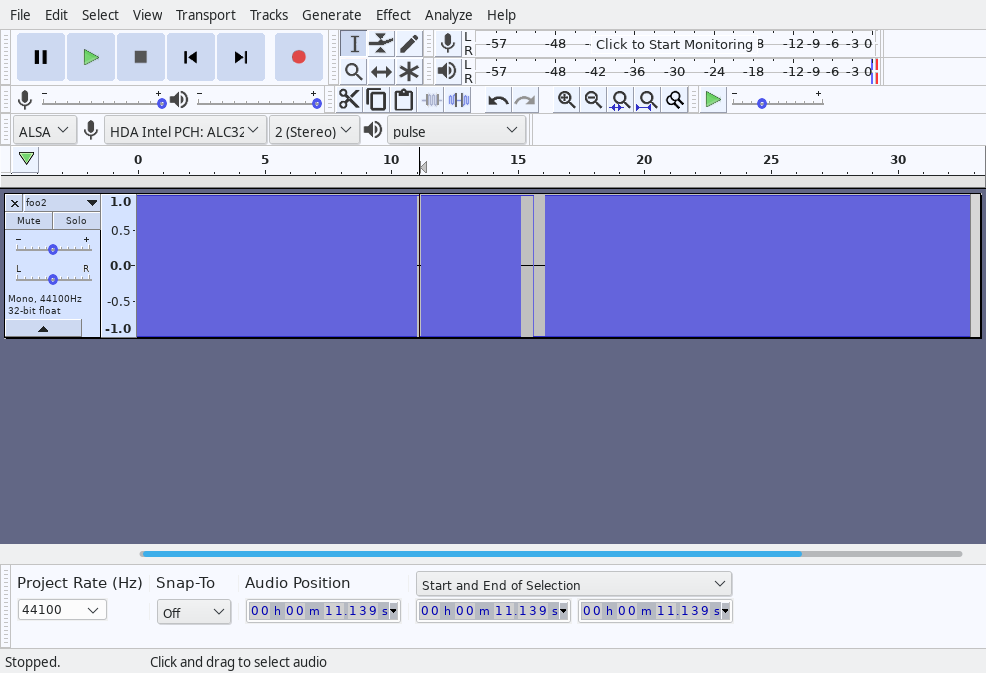
In this Audacity screenshot, there’s a short bit of silence at the 11 second mark. This is where the C64 will stop the motor and print “FOUND NAMEOFPROGRAM”. (Note that in the above .wav file, the name of the program is blank, so the C64 will only print “FOUND”.) When the motor stops, press the stop button. When the motor starts running again, reposition the cursor somewhere in the middle of the silent section (11.139s in this example) and press play.
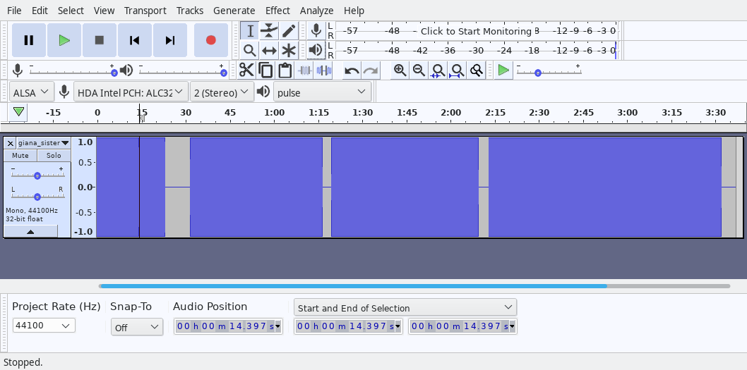
Here’s an Audacity screenshot for Great Giana Sisters (the tape version):
The cursor is positioned in the first short bit of silence, right after the “FOUND NAMEOFPROGRAM” but there are multiple points where the motor stops spinning and you will have to manually press stop/play each time.Great Giana Sisters! I think you had to press space to continue loading beyond this screen, which means you’d again need to manually press stop/play in Audacity
Now that we have talked about how to load .wav files into the C64, here’s how to actually generate .wav files:
Generating .wav files from .tap/.prg/.d64 files
I spent a few hours evaluating multiple solutions, and have found that wav-prg (https://wav-prg.sourceforge.io/) did the best job.
Here’s how to build this program on Linux:
git clone https://git.code.sf.net/p/wav-prg/libtap
cd wav-prg-libtap
make libtapdecoder.so
make libtapencoder.so
cd ..
git clone https://git.code.sf.net/p/wav-prg/libaudiotap
cd wav-prg-libaudiotap
make clean # probably not needed but happened to be in my notes, possibly for a reason
make -j4 DEBUG=y LINUX64BIT=y libaudiotap.so
cd ..
git clone https://git.code.sf.net/p/wav-prg/code
cd wav-prg-code
make clean # probably not needed but happened to be in my notes, possibly for a reason
make -j4 cmdline/wav2prg DEBUG=y AUDIOTAP_HDR=../wav-prg-libaudiotap/ AUDIOTAP_LIB=../wav-prg-libaudiotap/
make -j4 cmdline/prg2wav DEBUG=y AUDIOTAP_HDR=../wav-prg-libaudiotap/ AUDIOTAP_LIB=../wav-prg-libaudiotap/
Here are some example invocations for an NTSC C64. You can also generate .wav files for use with the PET (full explanation here) or the VIC-20.
# (pwd is .../wav-prg-code)
LD_LIBRARY_PATH=../wav-prg-libaudiotap/:../wav-prg-libtap/ cmdline/prg2wav -m c64ntsc -t filename.tap /path/to/prg # convert prg to tap image for use in vice etc.
LD_LIBRARY_PATH=../wav-prg-libaudiotap/:../wav-prg-libtap/ cmdline/prg2wav -m c64ntsc -w filename.wav /path/to/prg # convert prg directly to wav file
Here’s how to extract a .prg file from a .d64 floppy image, which you can then convert to a .wav file. All you need is VICE, which comes with a tool to extract data from .d64 files:
“ass”? :p Anyway, judging by the number of blocks, “block’n’bubble” seems like the program we’re most interested in. (You can try extracting the others and running them in an emulator.) To extract and to convert, run the following commands:
# (pwd is .../vice-3.5/src)
./c1541 -attach ~/retro/c64/software/BLOCKNB1.D64 -read "block'n'bubble" bnb.prg
reading file `block'n'bubble' from unit 8

# (change directory to .../wav-prg-code)
LD_LIBRARY_PATH=../wav-prg-libaudiotap/:../wav-prg-libtap/ cmdline/prg2wav -m c64ntsc -w bnb.wav bnb.prg # adjust input and output file paths
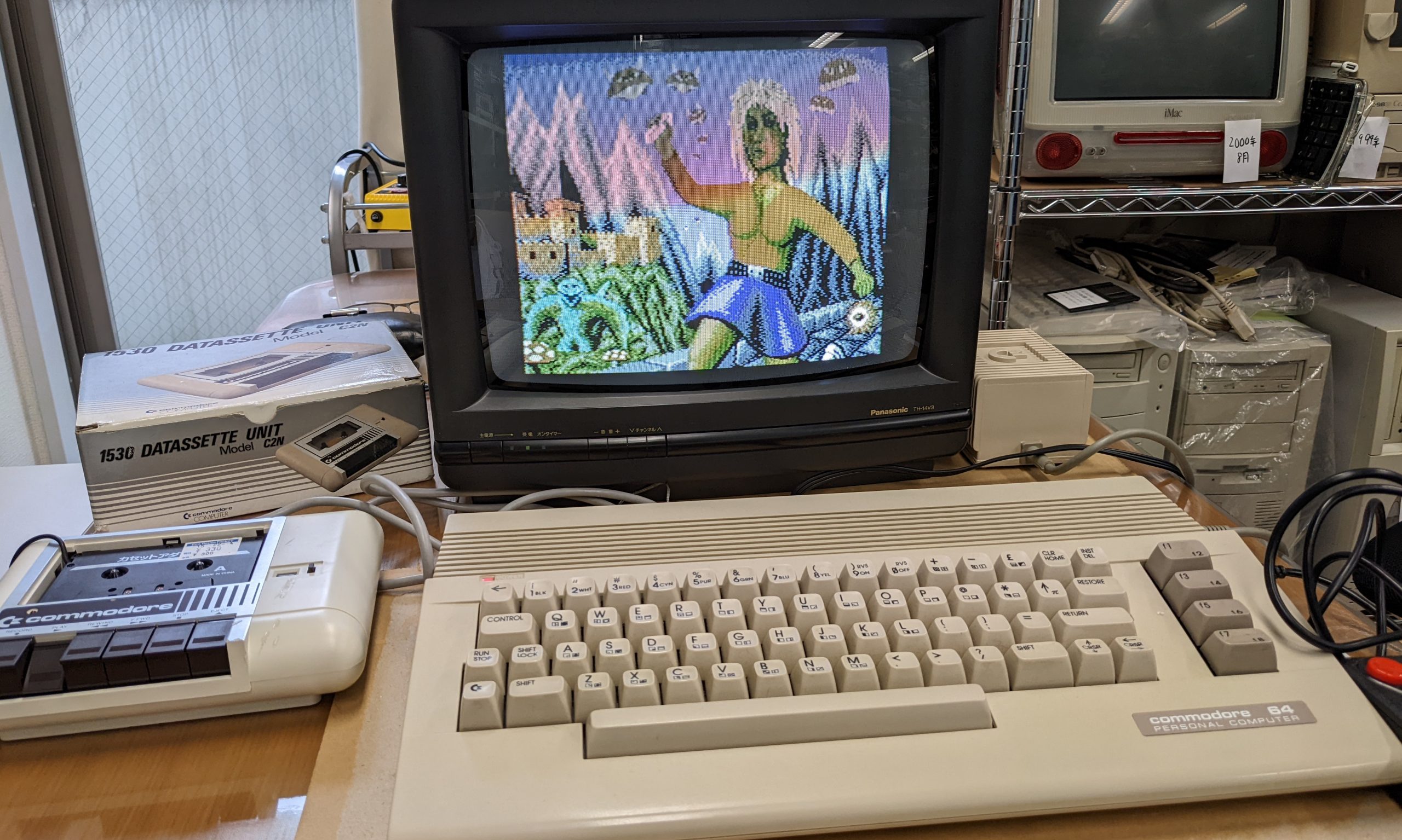
I don’t remember how to play, but I remember the intro screen music. Felt good to hear it played from a real Commodore 64 for the first time in 15-20 years! Here’s a clip. Sorry for the copyright violation:
Block’n’Bubble title music (looped)
The game’s playable as-is, but at least on my hardware the first time I started a game I got some weird colors. (The second time round the colors were normal.) Could be a PAL-vs.-NTSC issue, or could have something to do with the above conversion (for example, a program could assume that the C64’s tape buffer is available for temporary usage, but when loading from tape… it isn’t).
Note that large commercial software is often divided into multiple files, e.g., consisting of a loader and a main program, and perhaps a high score file. In that case, you will not be able to easily convert the software. (You would have to re-write the parts where the loader starts loading from the floppy, etc.)
It would probably require some hacking to convert this to tape.
However, not all commercial software is this complex. For example, using this method, I was able to convert the main .prg file in “JupiterLander_1982_Commodore.d64” to .tap and load this in VICE (didn’t try on real hardware but should work) and play as normal.
I recently had a look (multiple long looks) at a Commodore PET 2001 (with the ~first version of BASIC etc.) and a special character ROM with Japanese katakana instead of lower-case characters. I was told it had worked in around 2000 when it was last turned on. I went right in without knowing much about the Commodore PET.
Wobbly screen, junk characters on boot
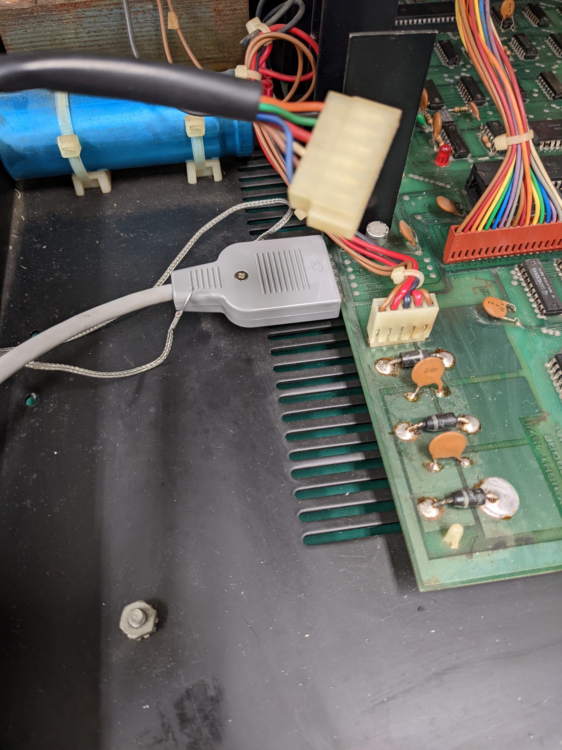
The wobbly/unstable/warped screen was caused by an oxidized and slightly broken molex connector supplying power to the board. This caused the voltages to jump between 4-5 volts multiple times per second. Well, nothing’s going to work that way. (Ideally I would have fixed this first, but I’d already noticed a bunch of other bad connections and didn’t think the molex connector would go bad.)
Stable screen, junk characters on boot
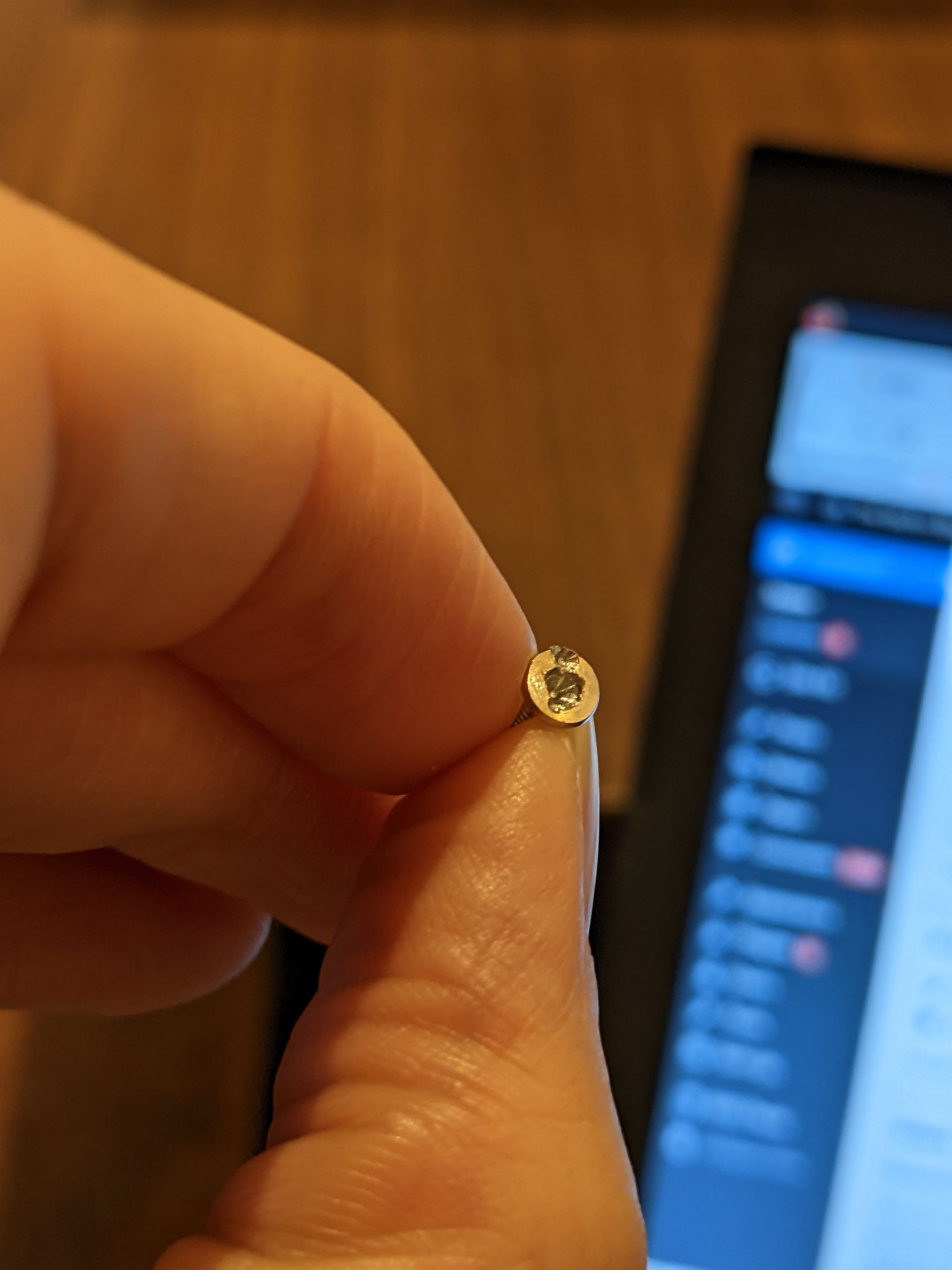
All chips that cost more than a couple cents (don’t know the prices in 1977 of course) were socketed. But boy, these are bad sockets. The one redeeming feature of the sockets that were used by Commodore at this time is that it’s easy to check if the inserted chip is making a connection with the socket. Just put your multimeter in continuity mode, one multimeter probe on the chip’s pin, and the other on the slightly exposed metal part belonging to the socket. No beep — bingo, that needs to be fixed.
This isn’t my machine and I’m not allowed to use contact cleaner (except IPA of course). I’m sure that contact cleaner would have helped here though. Anyway, not all of the bad connections were due to oxidization as far as I can tell — it seems like the socket and the pin just aren’t making physical contact, even after judicial use of IPA.
In these cases you can either replace the bad socket, or you can try to bend the chip’s legs to get better contact. I’d advise you not to do that with the chips in the PET; most of them were rather brittle in my case. Another thing you can do, and which I did here, is to put a new socket right on top of the existing socket. In most cases that’ll improve things immediately.
So I did that on all RAM chips after testing continuity almost everywhere (there was at least one pin that didn’t make contact on most chips) and all ROM chips except one (one didn’t have any bad contacts for some reason. The middle one, so maybe that one was more protected from the elements compared to ones closer to the edge?), and one of the 6520s. For the CPU and other chips, just re-seating did the trick.
Double sockets almost everywhere. I used extra high-quality sockets for the left-most RAM chips and the video RAM at the back, and (accidentally) in one other location.
One thing you have to know about the PET 2001 is that it’s possible to boot with just 2K (or even 1K?) of RAM. So make sure to put working RAM (making good contact) into the leftmost RAM sockets. If you have slightly faulty RAM, it doesn’t matter so much if you have that in the sockets beyond 2K. Your PET (if it boots) will tell you how many bytes of RAM you have free on boot. If it says 7167 bytes (on an 8K model), that means your RAM is probably fine. If it’s less than that, you probably have faulty RAM somewhere. (Broken RAM that misbehaves grossly may cause problems though.)
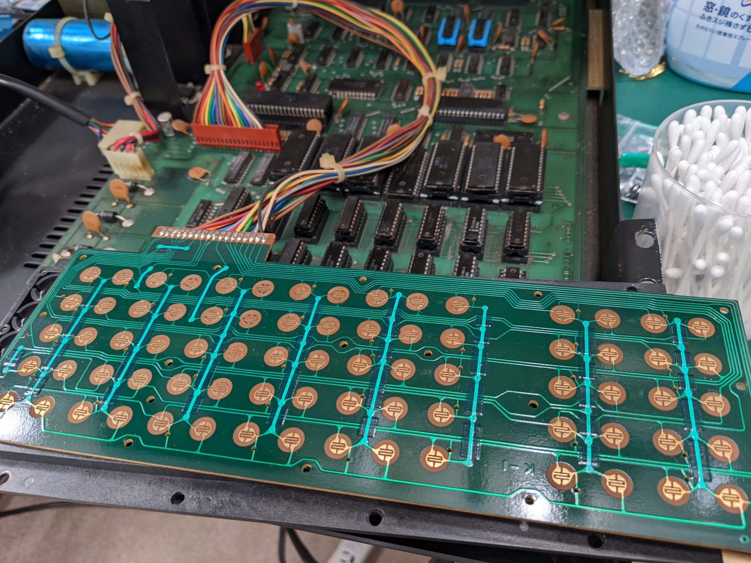
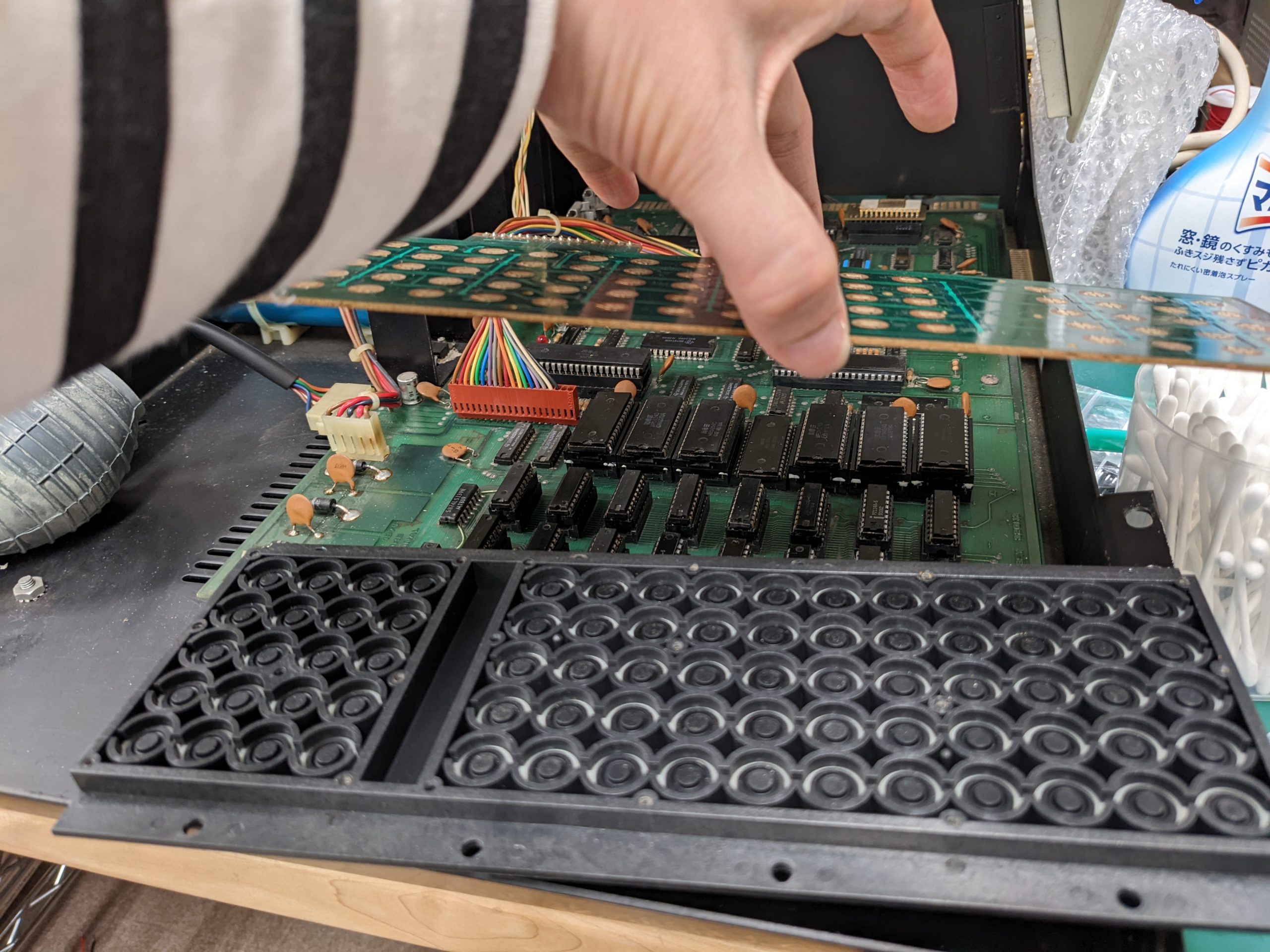
Keyboard fixes
If your PET has successfully booted, you should test all keys. If there are keys that don’t appear to work, try holding the key down for a little, or repeatedly pressing the key. If none of that helps, you will need to take apart the keyboard and clean it up using IPA. That fixed all problems for me.
Clean these contacts with IPAI also cleaned some of these conductive rubber? thingies with IPA, but only the ones on keys that were kind of problematic.
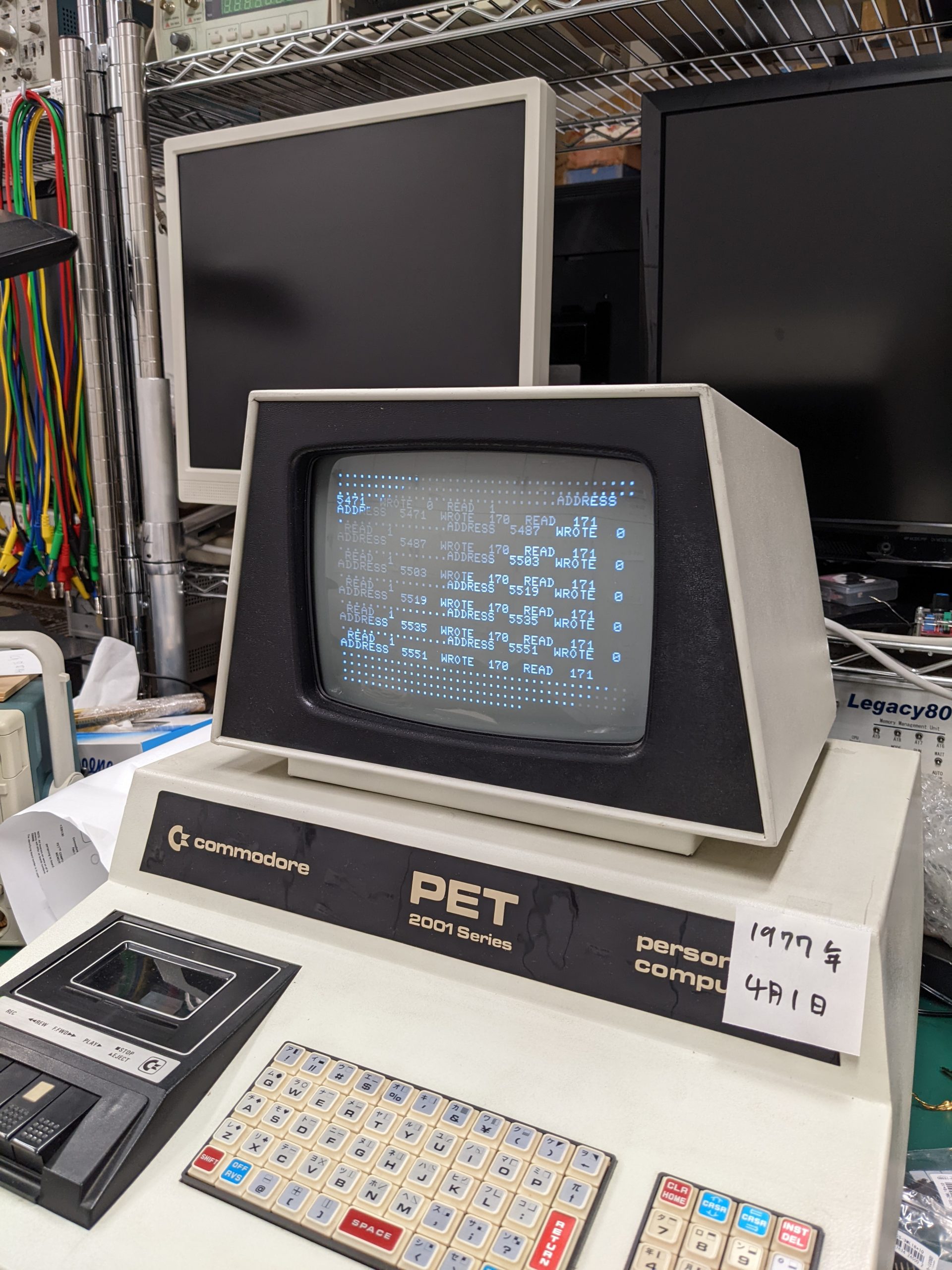
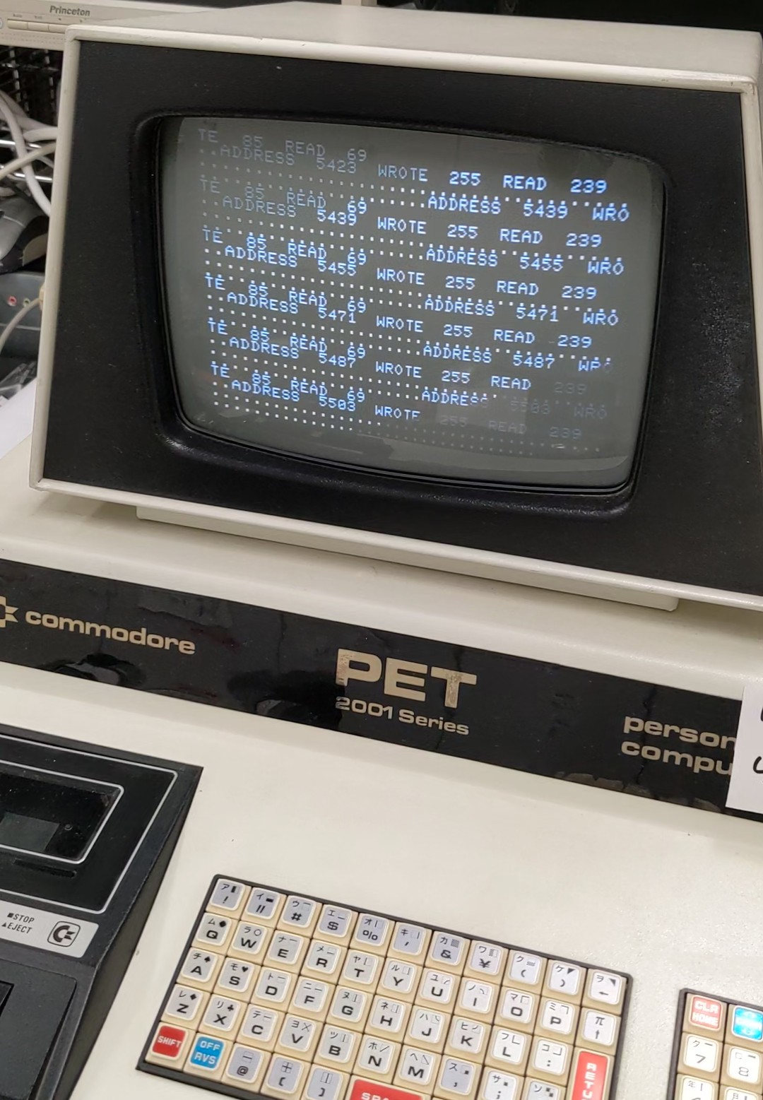
Testing RAM and ROM with a short BASIC program
If your PET has successfully booted, you may want to test your RAM and ROM chips. I found a BASIC script on the web to test RAM, but wasn’t able to run it back when my PET reported it only had 363 (or so) bytes free — the program was just too long. Original program from https://www.commodore.ca/commodore-manuals/commodore-pet-memory-test/. Here’s my modified version, which will work with much less RAM, has some visual feedback and isn’t that tough to type in.
5 INPUTA,B
20 FORI=ATOB
21 FORY=1TO4
22 READN
23 POKEI,N:X=PEEK(I)
24 IFX=NTHEN26
25 GOSUB200
26 NEXT
27 RESTORE
30 DATA0,85,170,255
120 PRINT "."
121 NEXT
130 PRINT "DONE"
140 END
200 PRINT "ADDRESS ";I;" WROTE ";N;" READ ";X
210 RETURN
Note that the PET firmware will place the BASIC code at address 1025+, variables go between 1946-2071, and arrays go from 2072-2231. As long as our BASIC code doesn’t use arrays, not too many variables, and isn’t too long, the system won’t need to access memory beyond 2K. So it’s safe to run this program on all RAM, from 2048 to 8191. (It’s pretty slow BTW, you may want to run it multiple times, in 2K steps.)
Found some RAM errors! Stuck bit.More RAM errors. Bit 3 (counting from 0) appears to be stuck at 0 here.
If you get errors, check the schematics for your board revision, re-test continuity between chip and socket on the supposedly faulty chip, and if there’s no connection error, replace it.
Here’s the ROM test, in ASM and BASIC (with data lines). On the PET, the ROM isn’t accessible from BASIC using PEEK, so assembly is required. Make sure you don’t make any mistakes when typing in the data lines.
.ORG = $1000
START:
LDA #0
LDY #$D0 ; stop when INC_ADDRESS+2 reaches this value
LOOP:
CLC ; clear carry flag, otherwise we'd add unneeded +1s
INC_ADDRESS:
ADC $C800 ; add contents of memory address $C800 to A (this address will be modified below)
JSR PRINT_HEX ; print out checksum for every added byte
INC INC_ADDRESS+1 ; increments insignificant byte
BNE LOOP ; if that address hasn't overflowed back to 0, go to LOOP
INC INC_ADDRESS+2 ; increments significant byte
CPY INC_ADDRESS+2 ; compare significant byte with Y register (into which we loaded the significant byte of the end address earlier)
BNE LOOP ; if unequal, go to LOOP
; JSR PRINT_HEX ; if we blazed past both BNEs then we're done so output checksum ; commented out because we currently print out the checksum for every added byte
RTS ; return from subroutine

PRINT_HEX:
PHA ; copy A to stack
LSR ; shift right 4 times so we get significant nibble
LSR
LSR
LSR
JSR PRINT_NIBBLE
PLA ; get fresh copy of A from stack
PHA ; and also write it back on stack
AND #$0f ; get lower nibble
JSR PRINT_NIBBLE
LDA #32 ; code for space
JSR $FFD2 ; print a space
PLA
RTS

PRINT_NIBBLE:
CMP #10 ; if we're >= 10
BCS HEX_ABCDEF ; branch
CLC ; clear carry flag, otherwise we'd add unneeded +1s
ADC #48 ; otherwise, add 48 to turn into a number
JSR $FFD2 ; print number
RTS ; return
HEX_ABCDEF: ; this is the a-f branch
CLC ; clear carry flag, otherwise we'd add unneeded +1s
ADC #55 ; we're at range 10-15 but want range 65-70, so add some
JSR $FFD2 ; print a-f
RTS
BASIC:
10 t=4096
15 input "decimal msb of start address"; sa
16 input "decimal msb of end address "; ea
17 input "carry over "; co
20 read x
30 if x=-1 then sys 4096:end
40 if x=-2 then poke t,sa:goto 80
50 if x=-3 then poke t,ea:goto 80
60 if x=-4 then poke t,co:goto 80
70 poke t,x
80 t=t+1
90 goto 20
1000data169,-4,160,-3,24,109,0,-2,32,25,16,238,6,16,208,244
1010data238,7,16,204,7,16,208,236,96,72,74,74,74,74,32,47
1020data16,104,72,41,15,32,47,16,169,32,32,210,255,104,96,201
1030data10,176,7,24,105,48,32,210,255,96,24,105,55,32,210,255
1040data96
1050data-1
Here’s a very lazy script (bin2data.sh) to assemble (using acme) and generate a simple BASIC loader:
#!/bin/bash

echo rem assuming compilation with acme --setpc 4096 -o foo check_rom.asm
echo
echo

echo '10 t=4096'
echo '20 read x:if x<>-1 then poke t,x:t=t+1:goto 20'
(od -Anone -tx1 $1 | perl -pe 's/([0-9a-fA-F]{2})/hex($1).","/eg' | sed -r -e 's/^/data/' -e 's/,$//'; echo 'data -1') | nl -i 10 -v 1000 -nln | sed -e 's/ //g' -e 's/ //g'
Here’s how to assemble using acme and use the bin2data.sh script:
Note that the BASIC listing above is almost identical to the output of the assembler script, except that I manually modified the output to place -4, -3, and -2 in the DATA lines. This is where the start/end addresses and the carry over go.
What this program does is sum up all values in the ROM. It also prints out the intermediate sum for each byte. Note that in the above loader, we poke the machine code into addresses 4096+. If you are on a 4K PET, that will not work. Just modify the .ORG, –setpc, and t=4096 lines in the assembly source, acme command line, and bin2data.sh, respectively.
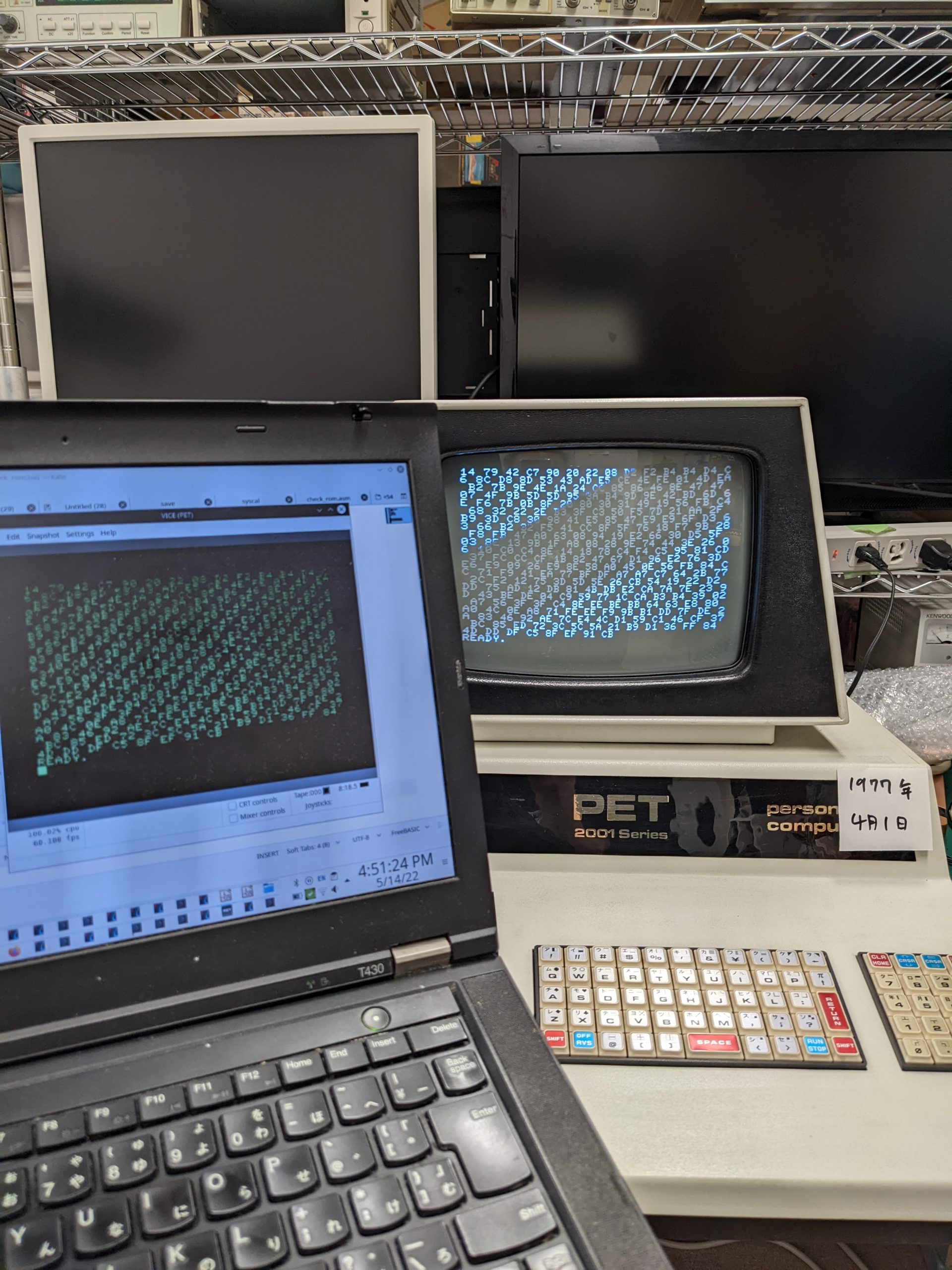
The ROMs on my machine are 2K each. Their addresses are 0xC000-0xC7FF (most significant byte in decimal: 192), 0xC800-0xCFFF (200), 0xD000-0xD7FF (208), 0xD800-0xDFFF (216), 0xE000-0xE7FF (224), 0xF000-0xF7FF (240), 0xF800-0xFFFF (248).
So you enter 192 for the start address, 200 for the (non-inclusive) end address, 0 for carry over. On my machine (and in VICE), the last few numbers are 8F EF 91 CB. Note: the ROMs at https://www.zimmers.net/anonftp/pub/cbm/firmware/computers/pet/index.html yield different checksums for this region.
I had the same checksums as the emulator for C000-C7FF, C800-CFFF, D000-D7FF, D800-DFFF, E000-E7FF, but different values for F000-F7FF and F800-FFFF. However, the checksums for F000 to FFFF were identical with rom-1-f000.901439-04.bin and rom/rom-1-f800.901439-07.bin downloaded from the above site.
Same values, yay
Here’s a very lazy script to compute the checksums using perl:
First of all, one thing that is useful to know is that you can connect the C64’s Datasette to the edge connector for the first tape drive on the PET’s mainboard. It’ll work just the same as the built-in drive. (However the Datasette’s plastic case may get in the way if you attempt to connect it to the edge connector for the second tape drive.)
Datasette drive connected to PET edge connector
You can even close the PET in this state without pinching the cable; I think there is around 1 cm of empty space between the base and the “lid” of the PET. (Which might be the reason everything is so dusty and oxidized in there.) So if you have a working Datasette drive, you may want to see if you can load/save programs using that.
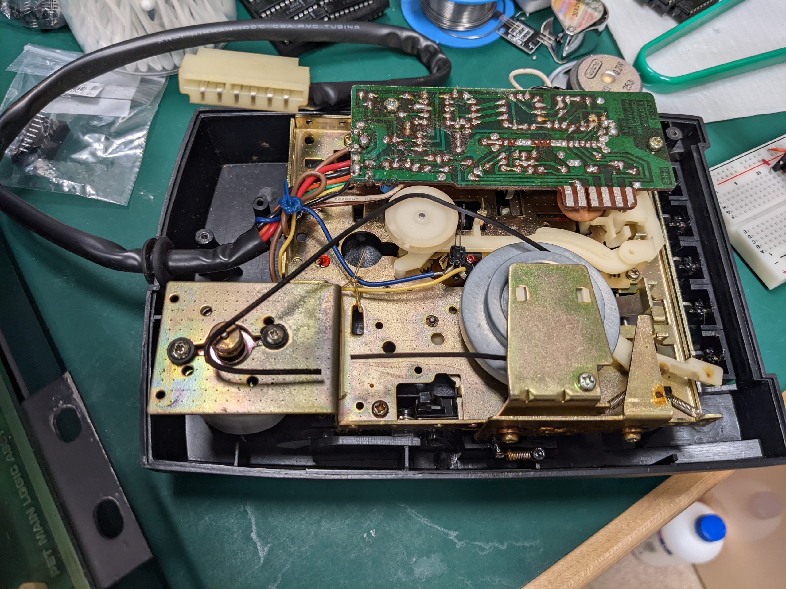
With a Datasette drive (for use with C64s and similar machines), it’s very easy to take off the cover (just lift it a bit further from it’s open position). With the cover removed, it’s very easy to put software on the PET using a 3.5mm/cassette adapter.
There’s one more step however, as these are .prg files. I used wav-prg to convert the .prg files into .wav files. Quick setup:
git clone https://git.code.sf.net/p/wav-prg/libaudiotap
git clone https://git.code.sf.net/p/wav-prg/libtap
git clone https://git.code.sf.net/p/wav-prg/code
cd wav-prg-libtap
make libtapdecoder.so
make libtapencoder.so
cd ../wav-prg-libaudiotap
make clean # may not be necessary but it's in my notes, perhaps for a reason
make -j4 DEBUG=y LINUX64BIT=y libaudiotap.so # DEBUG=y is in my notes, perhaps for a reason
cd ../wav-prg-code
make clean
make -j4 cmdline/wav2prg DEBUG=y AUDIOTAP_HDR=../wav-prg-libaudiotap/ AUDIOTAP_LIB=../wav-prg-libaudiotap/
make -j4 cmdline/prg2wav DEBUG=y AUDIOTAP_HDR=../wav-prg-libaudiotap/ AUDIOTAP_LIB=../wav-prg-libaudiotap/

# for PET: (-s seems to be required)
LD_LIBRARY_PATH=../wav-prg-libaudiotap/:../wav-prg-libtap/ cmdline/prg2wav -s -w space\ invader.wav space\ invader.prg
I don’t remember why, but I’d enabled debugging in my Makefiles as follows. It’s unlikely that these changes are needed.
Once you have .wav files, you can just use a cassette tape adapter for car stereos as described above. Unfortunately the edge connector for the PET’s second datasette drive doesn’t have enough clearance, so I disconnected the internal drive and once again connected the Datasette drive instead. Then you just type “load” and enter and press play, then you play back the .wav file from your computer.
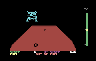
Here’s the title screen of a random game that I found that just so happened to almost work on the PET 2001 with some minor bugs (perhaps it was developed with a different machine in mind), Diamond Hunt II:
In a previous article we were able to see that one of our 4164 RAM chips didn’t produce a clear 0 or a clear 1 when asked to read from its memory. In this article we’ll hunt for more broken RAM chips by comparing the output from a known good 4164 RAM chip with the output of each installed 4164 RAM chip.
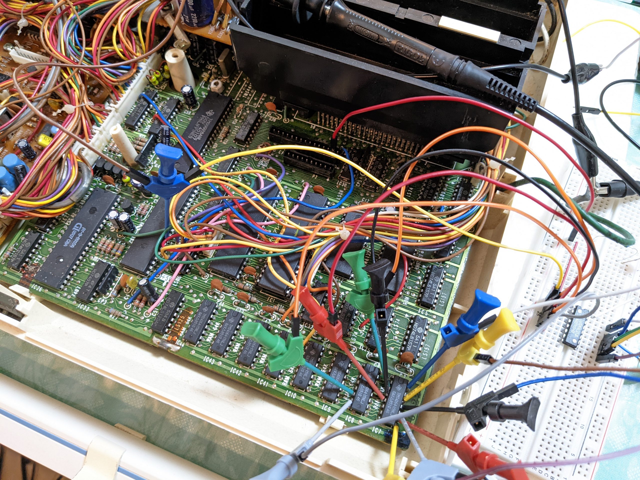
Basically, we place the known good 4164 RAM chip on a breadboard next to the computer to test, and then connect all address, RAS, CAS, WRITE and D pins to the equivalent pins on one of the 4164 RAM chips on the computer (by using tiny test clips, of which you will need at least 12, but more would be better). Then, we attach one oscilloscope probe to the Q pin on the known good 4164 RAM chip and one probe on the Q pin on the RAM chip to test (we’ll test each one, one by one). (Note that D and Q pins are often shorted, so if that is the case we can also attach the probe to the D pin on the RAM chip under test.)
We should then hold down the computer’s reset button and (while doing so) set the oscilloscope to trigger on a positive edge from the known good RAM chip’s Q pin, zoom out so we can capture a good amount of activity, and then release the reset button. We expect both chip’s outputs to be exactly the same. If there is a discrepancy, either the connections are bad, or we have found a broken RAM chip. (Be sure to check your connections using your multimeter’s continuity mode, and try hard not to touch the cables while probing around.)
Here’s a picture of my setup:
The keyboard connector on the Hitachi MB-H2 provides power. I’m measuring the right-most chip in this example, and to avoid having to touch the cables I’m taking D7 from a completely different chip. I’m also taking some of the address pins from a different RAM chip, just because that was easier.
If your testing shows that the RAM chips under test never produce the same signal as the reference known-good chip, then your wiring may be messed up. If on the other hand the signals always match up perfectly, then it seems likely that none of your RAM chips are bad. Finally, if there is a single RAM chip that often (but perhaps not always) produces a late signal or a different signal, you may have found a bad RAM chip.
In my case, most chips seemed to produce consistent signals. However, touching the cables often messed up signal integrity and I had to re-measure multiple times. I believe that the RAM chip for D7 was bad, as it often produced late or wrong signals even though the connections should have been stable.
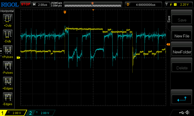
In the below video I’m scrolling along an oscilloscope capture. You can see that when the yellow line (which measures the output of the reference chip) goes high or low, the blue line also goes to (or stays at) the same level. This means that we’re getting the same output on both, which is good.
(There is a lot of other activity on the blue line, which we don’t know much about — some of it’ll be I/O to other chips, some will be writes to the RAM. The only thing we have that we can compare to is the Q output on the reference chip, so all we can do is check whether the transitions from 0 to 1 and from 1 to 0 on the output of the chip under test are correct. We are not able to check 1 to 1 or 0 to 0 outputs.)
For the less video-inclined readers, here is a screengrab showing a correct signal:
Confusing but okay signal
We have two transitions in the above screenshot. The first transition looks confusing at first because the blue signal takes a nosedive right after the yellow reference signal goes up — but that’s not too important, what matters is that they both have the same level for a short while. The blue line was already at “high” due to other I/O. (Also ignore the fact that the yellow line goes slightly higher than the blue one.) In the second transition we have a very neat and synchronized nosedive on both lines.
Here is a screengrab showing an erroneous signal:
Bad signal
Here we have two transitions on the yellow channel, and both times the blue channel goes to the exact opposite logic level. This isn’t perfect proof of a bad RAM chip — first of all we should make sure that this is repeatable and not due to wobbly probes. Second there is a slight possibility that some other device thinks it’s its turn to play with the bus (but normally that would show up as a voltage level somewhere between 0V and 5V).
I recently lost access to my Arduino for a couple days and decided to finally start playing around with my Raspberry Pi Pico. In case you don’t know, the Raspberry Pi Pico is even cheaper than most Arduinos. I think I paid 550 Japanese yen at a brick-and-mortar Marutsu for mine, and packs a lot of pins and quite some performance. (Amazon is way more expensive.)
So before we get to the 4164 tester, here’s my mini-review of the Raspberry Pi Pico from the perspective of someone who has never used a Raspberry Pi before and is used to his Arduino Nano:
The header pins weren’t attached so I had to solder them myself. I guess it’s possible to buy Picos with header pins soldered on, and I guess it’s also possible to buy Arduino Nanos without header pins. (Confirmed on amazon.co.jp). Soldering wasn’t too hard and I didn’t break anything.
Getting the (C/C++) development environment set up (on Debian Linux) wasn’t too hard for me personally, but I do this kind of thing a lot and would expect this to be much more difficult for someone who doesn’t have as much experience, especially if they are on a different distro. What I did was look at this script: https://raw.githubusercontent.com/raspberrypi/pico-setup/master/pico_setup.sh and instead of just running it, did the same things the script would have done — i.e., installed the prerequisite packages, cloned the relevant repositories, compiled and installed. If you can read bash scripts reasonably well you should be able to do this — otherwise you can just try and run the script verbatim and hope for the best. Note that the script is made to be run on a (non-Pico) Raspberry Pi.
The Arduino has an LED that is always on as long as there is power. The Pico has an onboard LED but it’s completely software-controlled. That’s great for non-beginners and perhaps not so great for beginners. (Is this thing even working?) To flash a program, you hold down a button and then connect USB. The Pico will identify as a sort of flash drive and you can copy over a .uf2 file. Once your OS is done copying (i.e. almost instantly) the Pico will immediately reboot and immediately start running your code. To the OS it will look like the flash drive suddenly disappeared. (This took me a little while to figure out.)
On the Arduino, you can be connected via serial at all times, though you’ll get a grey screen while flashing. On the Pico, USB serial feels much more “software-defined”, and you can’t be connected while re-flashing AFAICT. If you write a program that outputs something to serial right after starting, you probably won’t ever be able to see that output because your computer will take a while to notice there is something on USB. (For this reason, I added a 25 second pause at the beginning in my RAM tester program.)
So some parts of the development process are slightly more annoying than on the Arduino Nano, but the features may make up for it I think — more pins (but fewer analog I/O pins), much more performance, and step-by-step debugging via GDB (haven’t tried this yet).
One more very important thing to be aware of is that the Pico’s GPIO pins’ high logic level is 3.3V, not 5V. This doesn’t matter (IME) when driving the 4164’s input pins (address/RAS/CAS/WRITE/data in), but it’s likely to matter for the single GPIO pin connected to the 4164’s Q output pin. So you will need a resistor divider to bring the 4164’s 5V output down to 3.3V.
cmake_minimum_required(VERSION 3.12)

# Pull in SDK (must be before project)
include(pico_sdk_import.cmake)

project(pico_examples C CXX ASM)
set(CMAKE_C_STANDARD 11)
set(CMAKE_CXX_STANDARD 17)

if (PICO_SDK_VERSION_STRING VERSION_LESS "1.3.0")
    message(FATAL_ERROR "Raspberry Pi Pico SDK version 1.3.0 (or later) required. Your version is ${PICO_SDK_VERSION_STRING}")
endif()

set(PICO_EXAMPLES_PATH ${PROJECT_SOURCE_DIR})

# Initialize the SDK
pico_sdk_init()

include(example_auto_set_url.cmake)

add_compile_options(-Wall -Wextra
        -Wno-format          # int != int32_t as far as the compiler is concerned because gcc has int32_t as long int
        -Wno-unused-function # we have some for the docs that aren't called
        -Wno-maybe-uninitialized
        )

add_executable(4164_test
        4164_test.c
        )

# pull in common dependencies
target_link_libraries(4164_test pico_stdlib)

# enable usb output, disable uart output
pico_enable_stdio_usb(4164_test 1)
pico_enable_stdio_uart(4164_test 0)

# create map/bin/hex file etc.
pico_add_extra_outputs(4164_test)

# add url via pico_set_program_url
example_auto_set_url(4164_test)
4164_test.c
#include <stdio.h>
#include "pico/stdlib.h"

#define D           0
#define WRITE       1
#define RAS         2
#define A0          3
#define A2          4
#define A1          5

#define A7          16
#define A5          17
#define A4          18
#define A3          19
#define A6          20
#define Q           21
#define CAS         22

#define HIGH        1
#define LOW         0

#ifndef PICO_DEFAULT_LED_PIN
#error blink requires a board with a regular LED
#endif

#define STATUS_LED PICO_DEFAULT_LED_PIN
// #define STATUS_LED 15

#define BUS_SIZE 8
#define MAX_ERRORS 20
#define REFRESH_EVERY_N_WRITES 4
#define REFRESH_EVERY_N_READS 256 // 256 is the maximum for this implementation
#define N_REFRESHES 256

const unsigned int a_bus[BUS_SIZE] = {
  A0, A1, A2, A3, A4, A5, A6, A7
};

// #define debug_print printf
#define debug_print(...) ;

void nop(void) {
    __asm__ __volatile__( "nop\t\n");
}

void set_bus(unsigned int a) {
    int i;
    /* Write lowest bit into lowest address line first, then next-lowest bit, etc. */
    for (i = 0; i < BUS_SIZE; i++) {
        gpio_put(a_bus[i], a & 1);
        a >>= 1;
    }
}

void refresh() {
    int row;
    for (row = 0; row < 256; row++) {
        set_bus(row);
        gpio_put(RAS, LOW);
        nop();
        nop();
        nop();
        nop();
        nop();
        nop();
        nop();
        nop();
        nop();
        nop();
        nop();
        nop();
        nop();
        nop();
        nop();
        nop();
        nop();
        nop();
        nop();
        nop();
        gpio_put(RAS, HIGH);
    }
}

void write_address(int row, int col, bool val) {
    // Pull RAS and CAS HIGH
    gpio_put(RAS, HIGH);
    gpio_put(CAS, HIGH);

    // Set row address
    set_bus(row);

    // Pull RAS LOW
    gpio_put(RAS, LOW);
    nop(); // need to wait 15 ns before setting column address
    nop(); // need to wait 15 ns before setting column address
    nop(); // need to wait 15 ns before setting column address
    nop(); // need to wait 15 ns before setting column address

    // Set column address
    set_bus(col);

    // Pull CAS LOW
    gpio_put(CAS, LOW);

    // Set Data in pin to HIGH (write a one)
    gpio_put(D, val);

    // Pull Write LOW (Enables write)
    gpio_put(WRITE, LOW);

    sleep_us(1);
    gpio_put(WRITE, HIGH);
    gpio_put(CAS, HIGH);
    gpio_put(RAS, HIGH);
}

void read_address(int row, int col, bool *val) {
    // Pull RAS and CAS and WRITE HIGH
    gpio_put(RAS, HIGH);
    gpio_put(CAS, HIGH);
    gpio_put(WRITE, HIGH);

    // Set row address
    set_bus(row);

    // Pull RAS LOW
    gpio_put(RAS, LOW);
    nop(); // need to wait 15 ns before setting column address
    nop(); // need to wait 15 ns before setting column address
    nop(); // need to wait 15 ns before setting column address
    nop(); // need to wait 15 ns before setting column address

    // Set column address
    set_bus(col);

    // Pull CAS LOW
    gpio_put(CAS, LOW);

    sleep_us(1);

    *val = gpio_get(Q);

    gpio_put(WRITE, HIGH);
    gpio_put(CAS, HIGH);
    gpio_put(RAS, HIGH);
}

void setup() {
    bool dummy = false;
    int i;

    gpio_init(D);
    gpio_init(WRITE);
    gpio_init(RAS);
    gpio_init(A0);
    gpio_init(A2);
    gpio_init(A1);

    gpio_init(A7);
    gpio_init(A5);
    gpio_init(A4);
    gpio_init(A3);
    gpio_init(A6);
    gpio_init(Q);
    gpio_init(CAS);

    gpio_init(STATUS_LED);

    gpio_set_dir(D, GPIO_OUT);
    gpio_set_dir(WRITE, GPIO_OUT);
    gpio_set_dir(RAS, GPIO_OUT);
    gpio_set_dir(A0, GPIO_OUT);
    gpio_set_dir(A2, GPIO_OUT);
    gpio_set_dir(A1, GPIO_OUT);

    gpio_set_dir(A7, GPIO_OUT);
    gpio_set_dir(A5, GPIO_OUT);
    gpio_set_dir(A4, GPIO_OUT);
    gpio_set_dir(A3, GPIO_OUT);
    gpio_set_dir(A6, GPIO_OUT);
    gpio_set_dir(Q, GPIO_IN);
    gpio_set_dir(CAS, GPIO_OUT);

    gpio_set_dir(STATUS_LED, GPIO_OUT);

    gpio_put(RAS, HIGH);
    gpio_put(CAS, HIGH);
    gpio_put(WRITE, HIGH);
    gpio_put(D, LOW);
    gpio_put(A0, LOW);
    gpio_put(A1, LOW);
    gpio_put(A2, LOW);
    gpio_put(A3, LOW);
    gpio_put(A4, LOW);
    gpio_put(A5, LOW);
    gpio_put(A6, LOW);
    gpio_put(A7, LOW);

    sleep_us(1110);
    for (i = 0; i < 8; i++) {
        read_address(0, 0, &dummy);
        sleep_us(1);
    }
}

void test(bool start_val) {
    int row, col, refresh_count;
    int errors = 0;
    bool read_val = false;
    bool val = start_val;

    for (row = 0; row < 256; row++) {
        debug_print("Testing row: %d\n", row);
        for (col = 0; col < 256; col++) {
            gpio_put(STATUS_LED, val);
            write_address(row, col, val);
            read_address(row, col, &read_val);
            if (val != read_val) {
                printf("ERROR: row %d col %d read %d but expected %d\n", row, col, read_val, val);
                if (++errors > MAX_ERRORS) {
                    while (true) {
                        gpio_put(STATUS_LED, HIGH);
                        sleep_ms(50);
                        gpio_put(STATUS_LED, LOW);
                        sleep_ms(50);
                    }
                }
            }
            val = !val;
            gpio_put(STATUS_LED, val);
            if (col % REFRESH_EVERY_N_WRITES == 0) {
                refresh();
            }
        }
    }
    for (refresh_count = 0; refresh_count < N_REFRESHES; refresh_count++) {
        printf("Refresh test %d\n", refresh_count);
        val = start_val; // start from start_val (which determines whether we're testing 10101010... or 01010101...)
        for (row = 0; row < 256; row++) {
            for (col = 0; col < 256; col++) {
                gpio_put(STATUS_LED, val);
                read_address(row, col, &read_val);
                if (val != read_val) {
                    printf("ERROR: row %d col %d read %d but expected %d\n", row, col, read_val, val);
                    if (++errors > MAX_ERRORS) {
                        while (true) {
                            gpio_put(STATUS_LED, HIGH);
                            sleep_ms(50);
                            gpio_put(STATUS_LED, LOW);
                            sleep_ms(50);
                        }
                    }
                }
                val = !val;
                gpio_put(STATUS_LED, val);
                if (col % REFRESH_EVERY_N_READS == 0) {
                    refresh();
                }
            }
        }
    }
}

int main() {
    stdio_init_all();
    setup();

    sleep_ms(10000); // wait until /dev/ttyACM0 device is ready on host
    printf("Starting 10101010... test\n");
    test(true);
    printf("Starting 01010101... test\n");
    test(false);
    printf("Test done. All OK!\n");
    while (true) {
        gpio_put(STATUS_LED, HIGH);
        sleep_ms(1000);
        gpio_put(STATUS_LED, LOW);
        sleep_ms(1000);
    }
}
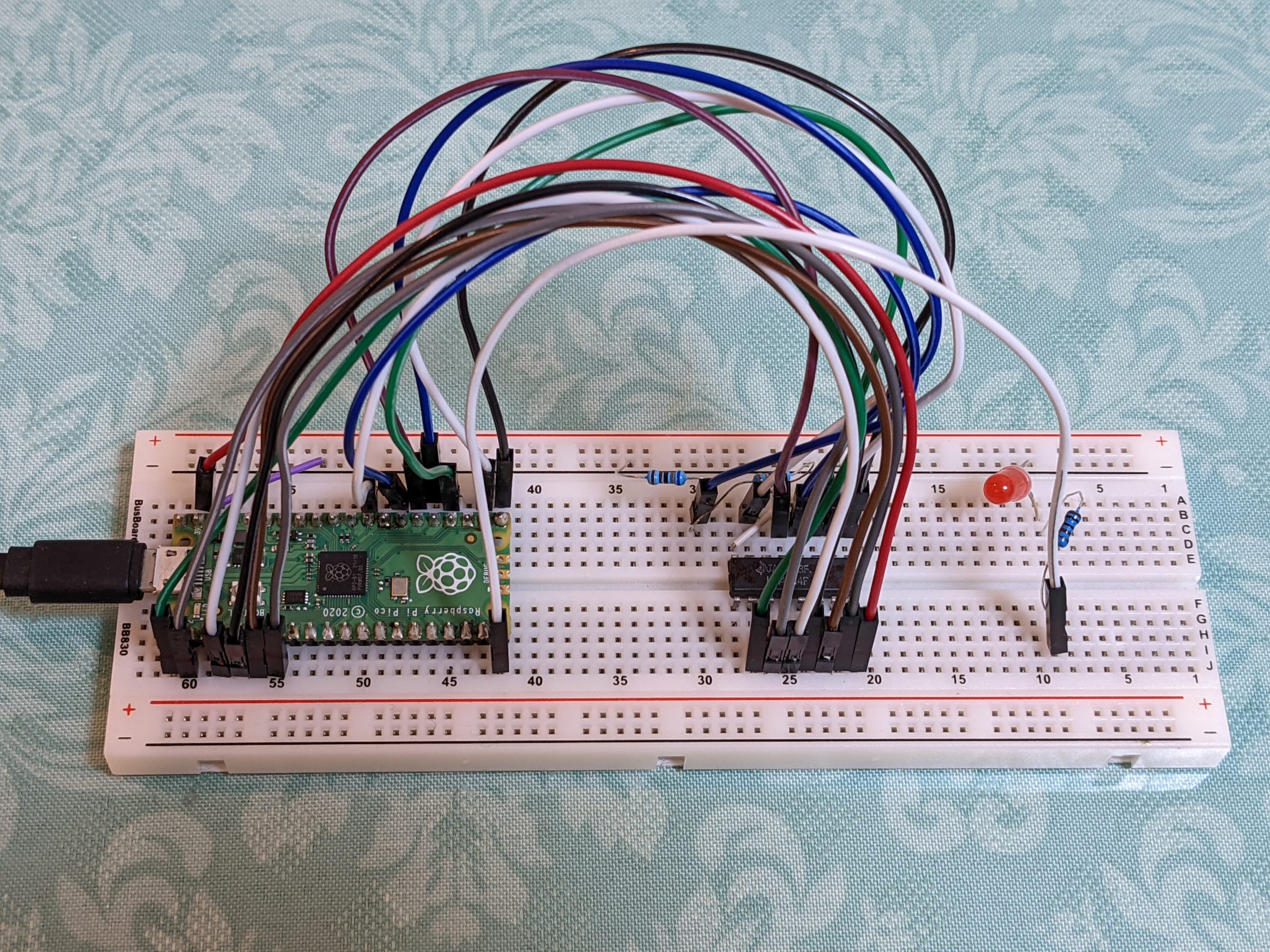
No cross connections
The Raspberry Pi Pico has a lot more pins than the Arduino Nano, which means that we can connect everything in a very straight and orderly manner. The pins on the left of the IC are connected to pins on the left of the Pico, and the pins on the right of the IC are connected to pins on the right of the Pico, and there are no cross connections. That’s a huge plus, and (as in our case) if you’ve got just one pin that requires level shifting, I’m not sure I’d choose the Arduino Nano if I already knew and owned both. Adjust the #defines at the top if you want to connect things differently.
Also, the Pico could theoretically allow much faster testing than the Nano, but my test is pretty slow, especially when using USB serial output. I also added a couple of delays to be super sure we don’t go out of spec. As the library only has millisecond and microsecond delays, I added a NOP-based delay (which probably delays things much more than required).
Note that this code won’t do anything the first ~10 seconds, this delay gives the host computer time to identify the USB serial device (should appear as /dev/ttyACM0). If you then execute, e.g., ‘minicom -D /dev/ttyACM0’ you should be able to see output as the test progresses. It’s also possible to see whether the test passed by looking at the onboard LED — fast blinking means error, slow blinking means success. If you prefer running tests using the LED, I suggest you do the following:
Set MAX_ERRORS to 0 (or remove the if (++error > MAX_ERRORS) logic entirely)
(The MAX_ERRORS logic causes the program to keep running after the first 20 errors, if you don’t want that, feel free to remove.)
There are three constants that control how refreshing works, REFRESH_EVERY_N_WRITES, REFRESH_EVERY_N_READS, and N_REFRESHES. If you want to test if your memory is refreshed correctly for a longer time, adjust N_REFRESHES.
To compile, copy the above files into a new directory, create a ‘build’ subdirectory and cd to it, run cmake and make:
mkdir build
cd build
cmake ../ -DCMAKE_BUILD_TYPE=Debug
make -j4
# hold BOOTSEL button while plugging in Pico USB
cp 4164_test.uf2 /media/.../RPI-RP2/