I recently lost access to my Arduino for a couple days and decided to finally start playing around with my Raspberry Pi Pico. In case you don’t know, the Raspberry Pi Pico is even cheaper than most Arduinos. I think I paid 550 Japanese yen at a brick-and-mortar Marutsu for mine, and packs a lot of pins and quite some performance. (Amazon is way more expensive.)
So before we get to the 4164 tester, here’s my mini-review of the Raspberry Pi Pico from the perspective of someone who has never used a Raspberry Pi before and is used to his Arduino Nano:
The header pins weren’t attached so I had to solder them myself. I guess it’s possible to buy Picos with header pins soldered on, and I guess it’s also possible to buy Arduino Nanos without header pins. (Confirmed on amazon.co.jp). Soldering wasn’t too hard and I didn’t break anything.
Getting the (C/C++) development environment set up (on Debian Linux) wasn’t too hard for me personally, but I do this kind of thing a lot and would expect this to be much more difficult for someone who doesn’t have as much experience, especially if they are on a different distro. What I did was look at this script: https://raw.githubusercontent.com/raspberrypi/pico-setup/master/pico_setup.sh and instead of just running it, did the same things the script would have done — i.e., installed the prerequisite packages, cloned the relevant repositories, compiled and installed. If you can read bash scripts reasonably well you should be able to do this — otherwise you can just try and run the script verbatim and hope for the best. Note that the script is made to be run on a (non-Pico) Raspberry Pi.
The Arduino has an LED that is always on as long as there is power. The Pico has an onboard LED but it’s completely software-controlled. That’s great for non-beginners and perhaps not so great for beginners. (Is this thing even working?) To flash a program, you hold down a button and then connect USB. The Pico will identify as a sort of flash drive and you can copy over a .uf2 file. Once your OS is done copying (i.e. almost instantly) the Pico will immediately reboot and immediately start running your code. To the OS it will look like the flash drive suddenly disappeared. (This took me a little while to figure out.)
On the Arduino, you can be connected via serial at all times, though you’ll get a grey screen while flashing. On the Pico, USB serial feels much more “software-defined”, and you can’t be connected while re-flashing AFAICT. If you write a program that outputs something to serial right after starting, you probably won’t ever be able to see that output because your computer will take a while to notice there is something on USB. (For this reason, I added a 25 second pause at the beginning in my RAM tester program.)
So some parts of the development process are slightly more annoying than on the Arduino Nano, but the features may make up for it I think — more pins (but fewer analog I/O pins), much more performance, and step-by-step debugging via GDB (haven’t tried this yet).
One more very important thing to be aware of is that the Pico’s GPIO pins’ high logic level is 3.3V, not 5V. This doesn’t matter (IME) when driving the 4164’s input pins (address/RAS/CAS/WRITE/data in), but it’s likely to matter for the single GPIO pin connected to the 4164’s Q output pin. So you will need a resistor divider to bring the 4164’s 5V output down to 3.3V.
Update 2023/08/07: the code is also available on GitHub: https://github.com/qiqitori/pico_4164_tester
The code consists of three files, a very standard CMakeLists.txt (pretty much a straight amalgam of https://github.com/raspberrypi/pico-examples/blob/master/CMakeLists.txt and https://github.com/raspberrypi/pico-examples/blob/master/hello_world/usb/CMakeLists.txt), pico_sdk_import.cmake (straight from https://github.com/raspberrypi/pico-examples/blob/master/pico_sdk_import.cmake), and 4164_test.c. Some of the code in 4164_test.c has been adapted from https://ezcontents.org/4164-dynamic-ram-arduino.
CMakeLists.txt
cmake_minimum_required(VERSION 3.12)

# Pull in SDK (must be before project)
include(pico_sdk_import.cmake)

project(pico_examples C CXX ASM)
set(CMAKE_C_STANDARD 11)
set(CMAKE_CXX_STANDARD 17)

if (PICO_SDK_VERSION_STRING VERSION_LESS "1.3.0")
    message(FATAL_ERROR "Raspberry Pi Pico SDK version 1.3.0 (or later) required. Your version is ${PICO_SDK_VERSION_STRING}")
endif()

set(PICO_EXAMPLES_PATH ${PROJECT_SOURCE_DIR})

# Initialize the SDK
pico_sdk_init()

include(example_auto_set_url.cmake)

add_compile_options(-Wall -Wextra
        -Wno-format          # int != int32_t as far as the compiler is concerned because gcc has int32_t as long int
        -Wno-unused-function # we have some for the docs that aren't called
        -Wno-maybe-uninitialized
        )

add_executable(4164_test
        4164_test.c
        )

# pull in common dependencies
target_link_libraries(4164_test pico_stdlib)

# enable usb output, disable uart output
pico_enable_stdio_usb(4164_test 1)
pico_enable_stdio_uart(4164_test 0)

# create map/bin/hex file etc.
pico_add_extra_outputs(4164_test)

# add url via pico_set_program_url
example_auto_set_url(4164_test)
4164_test.c
#include <stdio.h>
#include "pico/stdlib.h"

#define D           0
#define WRITE       1
#define RAS         2
#define A0          3
#define A2          4
#define A1          5

#define A7          16
#define A5          17
#define A4          18
#define A3          19
#define A6          20
#define Q           21
#define CAS         22

#define HIGH        1
#define LOW         0

#ifndef PICO_DEFAULT_LED_PIN
#error blink requires a board with a regular LED
#endif

#define STATUS_LED PICO_DEFAULT_LED_PIN
// #define STATUS_LED 15

#define BUS_SIZE 8
#define MAX_ERRORS 20
#define REFRESH_EVERY_N_WRITES 4
#define REFRESH_EVERY_N_READS 256 // 256 is the maximum for this implementation
#define N_REFRESHES 256

const unsigned int a_bus[BUS_SIZE] = {
  A0, A1, A2, A3, A4, A5, A6, A7
};

// #define debug_print printf
#define debug_print(...) ;

void nop(void) {
    __asm__ __volatile__( "nop\t\n");
}

void set_bus(unsigned int a) {
    int i;
    /* Write lowest bit into lowest address line first, then next-lowest bit, etc. */
    for (i = 0; i < BUS_SIZE; i++) {
        gpio_put(a_bus[i], a & 1);
        a >>= 1;
    }
}

void refresh() {
    int row;
    for (row = 0; row < 256; row++) {
        set_bus(row);
        gpio_put(RAS, LOW);
        nop();
        nop();
        nop();
        nop();
        nop();
        nop();
        nop();
        nop();
        nop();
        nop();
        nop();
        nop();
        nop();
        nop();
        nop();
        nop();
        nop();
        nop();
        nop();
        nop();
        gpio_put(RAS, HIGH);
    }
}

void write_address(int row, int col, bool val) {
    // Pull RAS and CAS HIGH
    gpio_put(RAS, HIGH);
    gpio_put(CAS, HIGH);

    // Set row address
    set_bus(row);

    // Pull RAS LOW
    gpio_put(RAS, LOW);
    nop(); // need to wait 15 ns before setting column address
    nop(); // need to wait 15 ns before setting column address
    nop(); // need to wait 15 ns before setting column address
    nop(); // need to wait 15 ns before setting column address

    // Set column address
    set_bus(col);

    // Pull CAS LOW
    gpio_put(CAS, LOW);

    // Set Data in pin to HIGH (write a one)
    gpio_put(D, val);

    // Pull Write LOW (Enables write)
    gpio_put(WRITE, LOW);

    sleep_us(1);
    gpio_put(WRITE, HIGH);
    gpio_put(CAS, HIGH);
    gpio_put(RAS, HIGH);
}

void read_address(int row, int col, bool *val) {
    // Pull RAS and CAS and WRITE HIGH
    gpio_put(RAS, HIGH);
    gpio_put(CAS, HIGH);
    gpio_put(WRITE, HIGH);

    // Set row address
    set_bus(row);

    // Pull RAS LOW
    gpio_put(RAS, LOW);
    nop(); // need to wait 15 ns before setting column address
    nop(); // need to wait 15 ns before setting column address
    nop(); // need to wait 15 ns before setting column address
    nop(); // need to wait 15 ns before setting column address

    // Set column address
    set_bus(col);

    // Pull CAS LOW
    gpio_put(CAS, LOW);

    sleep_us(1);

    *val = gpio_get(Q);

    gpio_put(WRITE, HIGH);
    gpio_put(CAS, HIGH);
    gpio_put(RAS, HIGH);
}

void setup() {
    bool dummy = false;
    int i;

    gpio_init(D);
    gpio_init(WRITE);
    gpio_init(RAS);
    gpio_init(A0);
    gpio_init(A2);
    gpio_init(A1);

    gpio_init(A7);
    gpio_init(A5);
    gpio_init(A4);
    gpio_init(A3);
    gpio_init(A6);
    gpio_init(Q);
    gpio_init(CAS);

    gpio_init(STATUS_LED);

    gpio_set_dir(D, GPIO_OUT);
    gpio_set_dir(WRITE, GPIO_OUT);
    gpio_set_dir(RAS, GPIO_OUT);
    gpio_set_dir(A0, GPIO_OUT);
    gpio_set_dir(A2, GPIO_OUT);
    gpio_set_dir(A1, GPIO_OUT);

    gpio_set_dir(A7, GPIO_OUT);
    gpio_set_dir(A5, GPIO_OUT);
    gpio_set_dir(A4, GPIO_OUT);
    gpio_set_dir(A3, GPIO_OUT);
    gpio_set_dir(A6, GPIO_OUT);
    gpio_set_dir(Q, GPIO_IN);
    gpio_set_dir(CAS, GPIO_OUT);

    gpio_set_dir(STATUS_LED, GPIO_OUT);

    gpio_put(RAS, HIGH);
    gpio_put(CAS, HIGH);
    gpio_put(WRITE, HIGH);
    gpio_put(D, LOW);
    gpio_put(A0, LOW);
    gpio_put(A1, LOW);
    gpio_put(A2, LOW);
    gpio_put(A3, LOW);
    gpio_put(A4, LOW);
    gpio_put(A5, LOW);
    gpio_put(A6, LOW);
    gpio_put(A7, LOW);

    sleep_us(1110);
    for (i = 0; i < 8; i++) {
        read_address(0, 0, &dummy);
        sleep_us(1);
    }
}

void test(bool start_val) {
    int row, col, refresh_count;
    int errors = 0;
    bool read_val = false;
    bool val = start_val;

    for (row = 0; row < 256; row++) {
        debug_print("Testing row: %d\n", row);
        for (col = 0; col < 256; col++) {
            gpio_put(STATUS_LED, val);
            write_address(row, col, val);
            read_address(row, col, &read_val);
            if (val != read_val) {
                printf("ERROR: row %d col %d read %d but expected %d\n", row, col, read_val, val);
                if (++errors > MAX_ERRORS) {
                    while (true) {
                        gpio_put(STATUS_LED, HIGH);
                        sleep_ms(50);
                        gpio_put(STATUS_LED, LOW);
                        sleep_ms(50);
                    }
                }
            }
            val = !val;
            gpio_put(STATUS_LED, val);
            if (col % REFRESH_EVERY_N_WRITES == 0) {
                refresh();
            }
        }
    }
    for (refresh_count = 0; refresh_count < N_REFRESHES; refresh_count++) {
        printf("Refresh test %d\n", refresh_count);
        val = start_val; // start from start_val (which determines whether we're testing 10101010... or 01010101...)
        for (row = 0; row < 256; row++) {
            for (col = 0; col < 256; col++) {
                gpio_put(STATUS_LED, val);
                read_address(row, col, &read_val);
                if (val != read_val) {
                    printf("ERROR: row %d col %d read %d but expected %d\n", row, col, read_val, val);
                    if (++errors > MAX_ERRORS) {
                        while (true) {
                            gpio_put(STATUS_LED, HIGH);
                            sleep_ms(50);
                            gpio_put(STATUS_LED, LOW);
                            sleep_ms(50);
                        }
                    }
                }
                val = !val;
                gpio_put(STATUS_LED, val);
                if (col % REFRESH_EVERY_N_READS == 0) {
                    refresh();
                }
            }
        }
    }
}

int main() {
    stdio_init_all();
    setup();

    sleep_ms(10000); // wait until /dev/ttyACM0 device is ready on host
    printf("Starting 10101010... test\n");
    test(true);
    printf("Starting 01010101... test\n");
    test(false);
    printf("Test done. All OK!\n");
    while (true) {
        gpio_put(STATUS_LED, HIGH);
        sleep_ms(1000);
        gpio_put(STATUS_LED, LOW);
        sleep_ms(1000);
    }
}
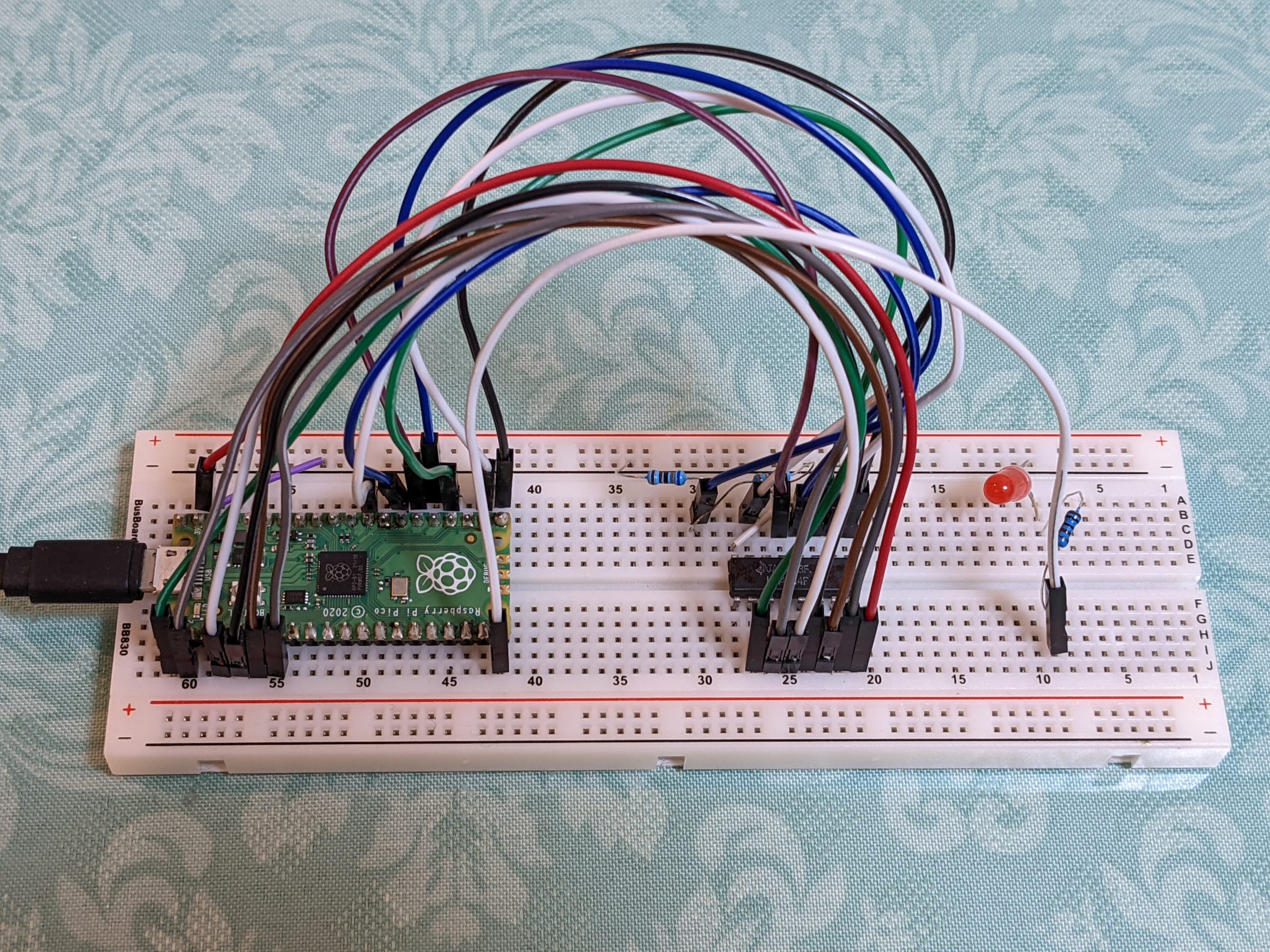
The Raspberry Pi Pico has a lot more pins than the Arduino Nano, which means that we can connect everything in a very straight and orderly manner. The pins on the left of the IC are connected to pins on the left of the Pico, and the pins on the right of the IC are connected to pins on the right of the Pico, and there are no cross connections. That’s a huge plus, and (as in our case) if you’ve got just one pin that requires level shifting, I’m not sure I’d choose the Arduino Nano if I already knew and owned both. Adjust the #defines at the top if you want to connect things differently.
Also, the Pico could theoretically allow much faster testing than the Nano, but my test is pretty slow, especially when using USB serial output. I also added a couple of delays to be super sure we don’t go out of spec. As the library only has millisecond and microsecond delays, I added a NOP-based delay (which probably delays things much more than required).
Note that this code won’t do anything the first ~10 seconds, this delay gives the host computer time to identify the USB serial device (should appear as /dev/ttyACM0). If you then execute, e.g., ‘minicom -D /dev/ttyACM0’ you should be able to see output as the test progresses. It’s also possible to see whether the test passed by looking at the onboard LED — fast blinking means error, slow blinking means success. If you prefer running tests using the LED, I suggest you do the following:
- Comment out the sleep_ms(10000); call
- Remove ‘#define println printf’, add ‘#define println(…) ;’ instead
- Set MAX_ERRORS to 0 (or remove the if (++error > MAX_ERRORS) logic entirely)
(The MAX_ERRORS logic causes the program to keep running after the first 20 errors, if you don’t want that, feel free to remove.)
There are three constants that control how refreshing works, REFRESH_EVERY_N_WRITES, REFRESH_EVERY_N_READS, and N_REFRESHES. If you want to test if your memory is refreshed correctly for a longer time, adjust N_REFRESHES.
To compile, copy the above files into a new directory, create a ‘build’ subdirectory and cd to it, run cmake and make:
mkdir build
cd build
cmake ../ -DCMAKE_BUILD_TYPE=Debug
make -j4
# hold BOOTSEL button while plugging in Pico USB
cp 4164_test.uf2 /media/.../RPI-RP2/