Cloning an old (extremely difficult) puzzle game made by the company that probably invented Sokoban

Link to game for impatient readers: https://blog.qiqitori.com/tnt_bomb_bomb/
シンキングラビットのTNTボムボムのJavaScript版です。どうぞお遊びください。
以下は英語しかありません。(´・ω・`)

I like Sokoban. A while ago, I saw someone play a Sokoban-like game called T.N.T. Bomb Bomb on a Sharp MZ-1500. I wanted it and almost immediately headed to the internets to find a disk image or ROM or whatever of it. And while I could find references and YouTube videos, I couldn’t find anything playable. (Note 1: me not being able to find the ROM doesn’t mean that it really doesn’t exist, of course. In fact, maybe this isn’t the first clone of these levels either. Note 2: it is likely that this copy of the game will be properly dumped in the near future.)

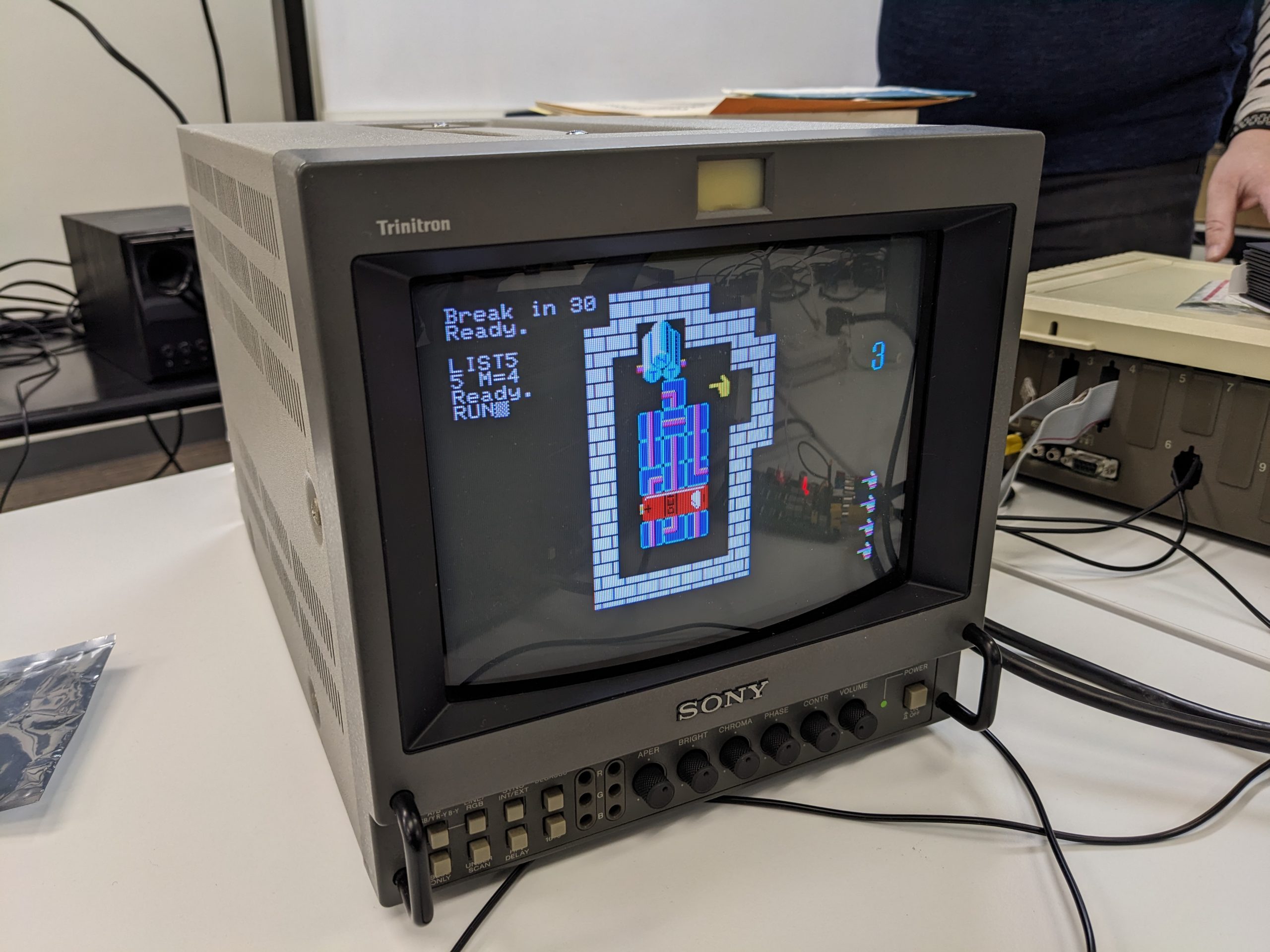
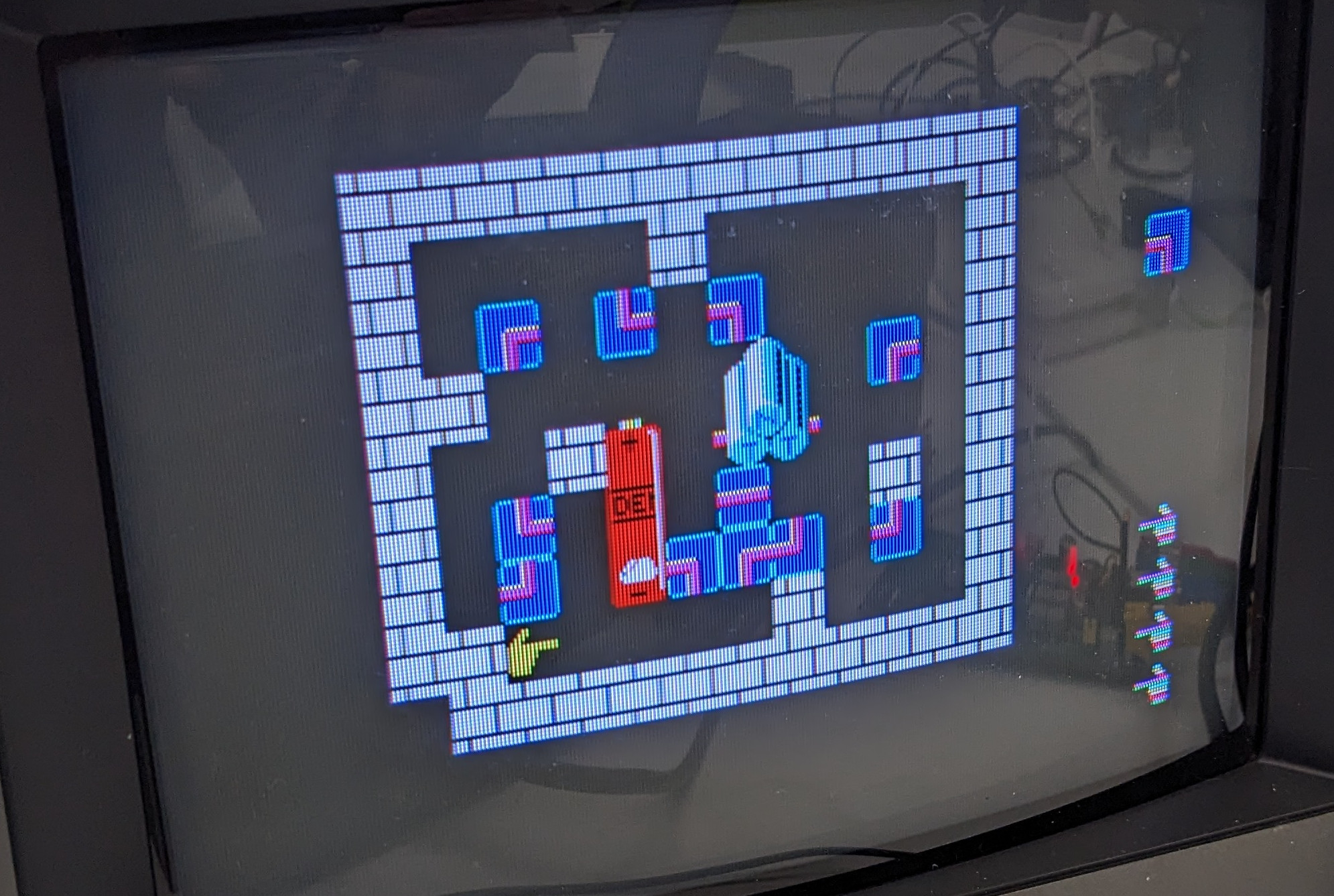
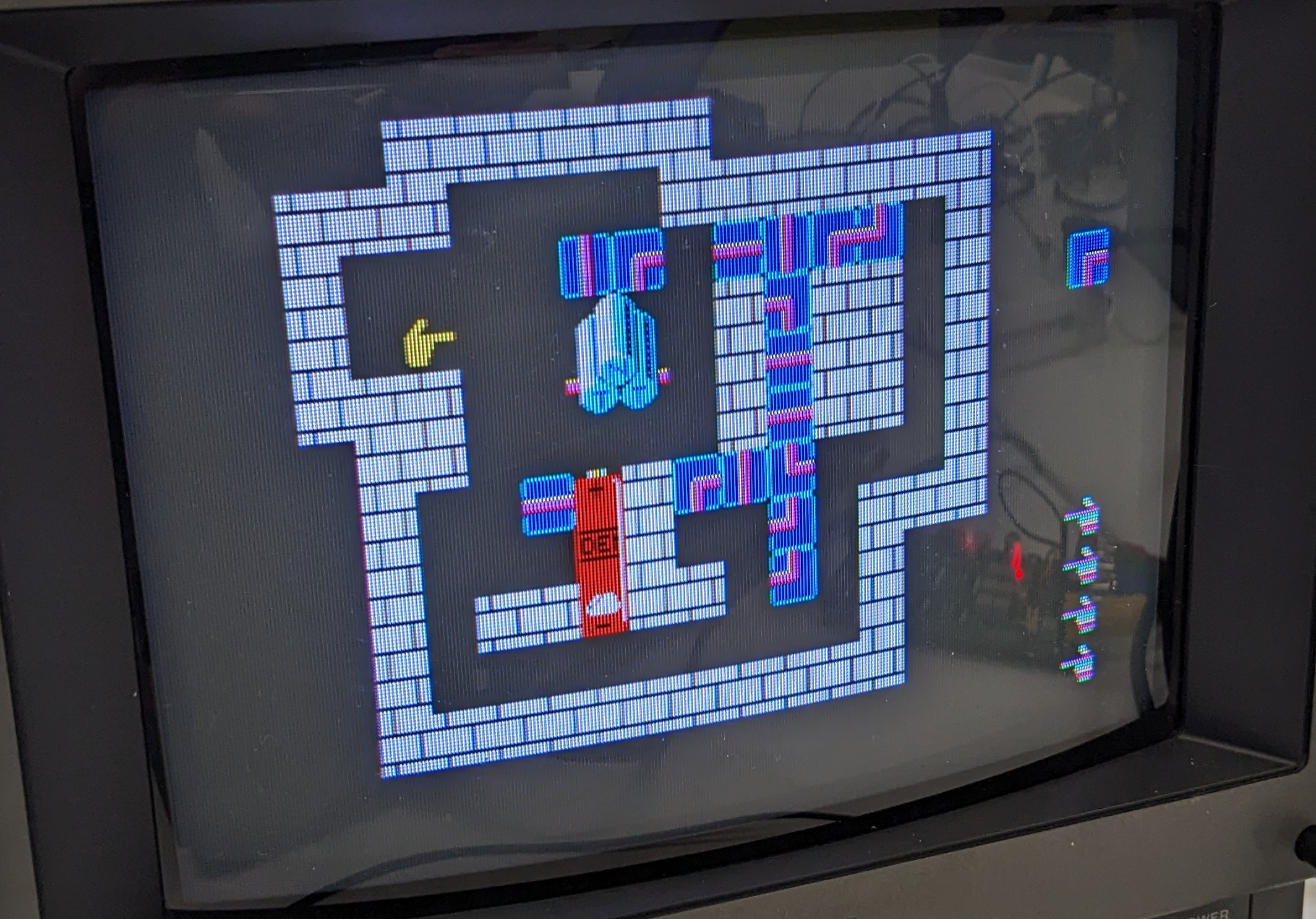
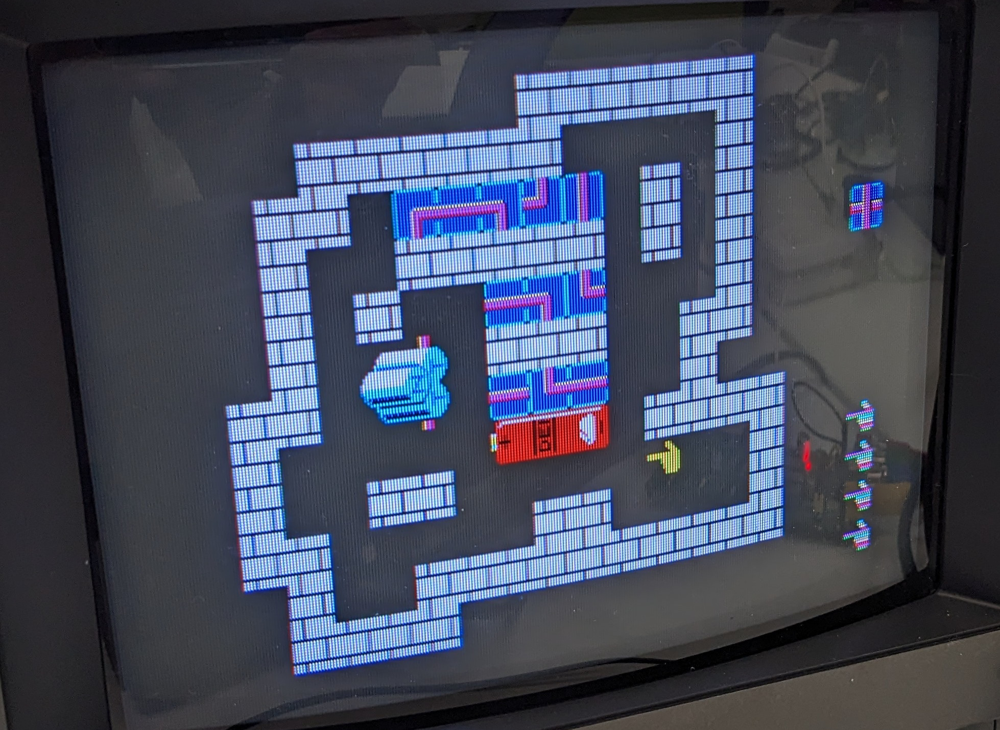
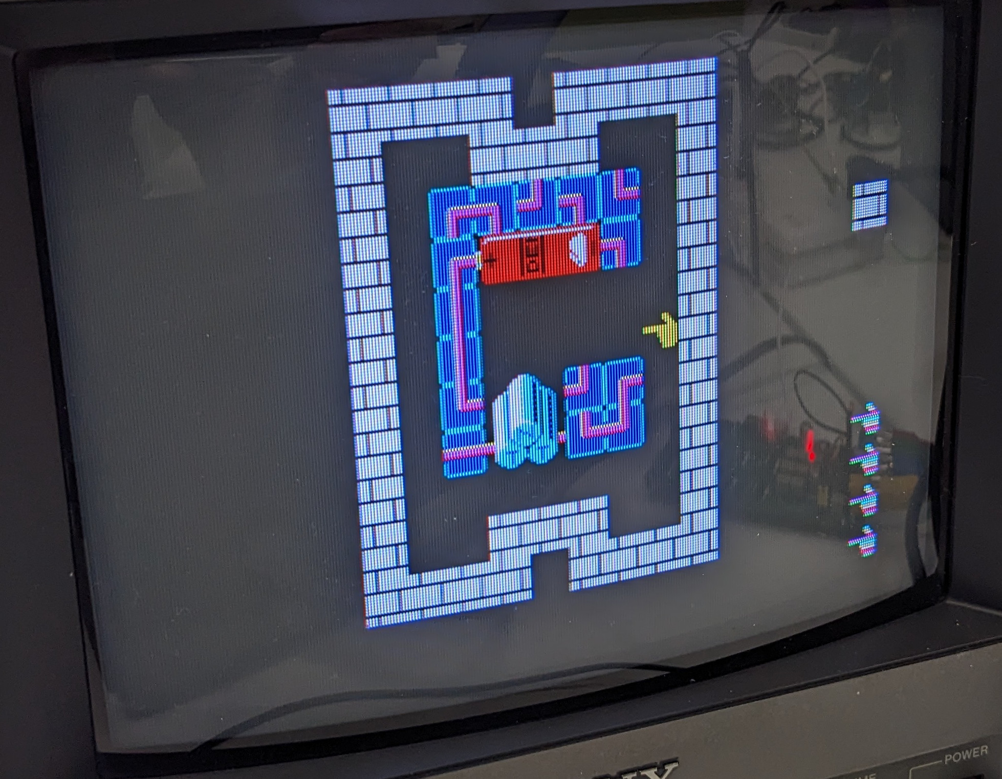
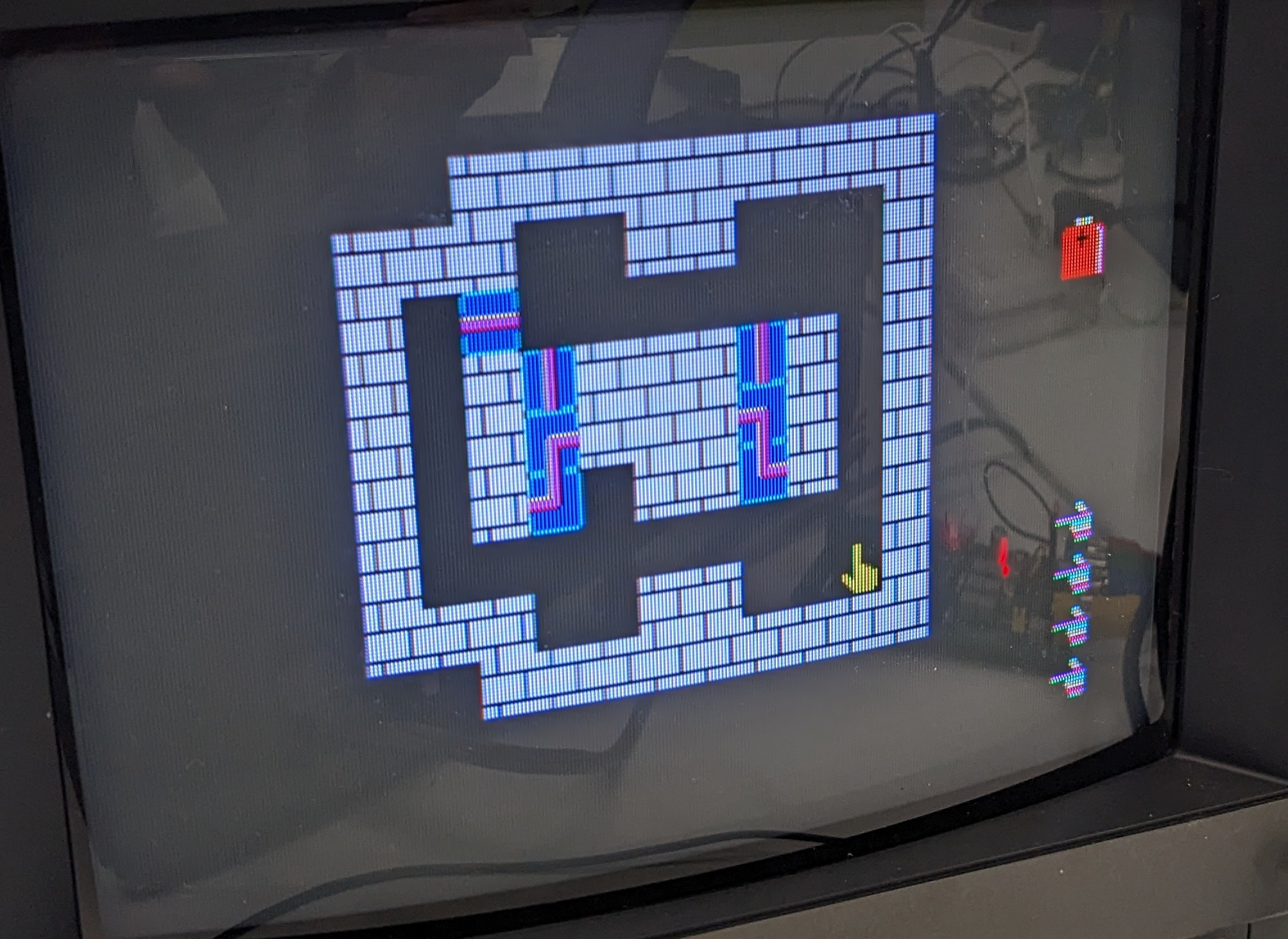
Fortunately, the game is partially implemented in BASIC. Which means you could just press Shift+Break and type LIST whenever you wanted! Then you could very easily modify variables and type RUN and play with extra lives or whatever. In my case, I just wanted a picture of every level, so I added a line (line 5) to specify the level to show, hit RUN, and took a picture. Here’s an example:

Hitting enter in this state will render level 4.

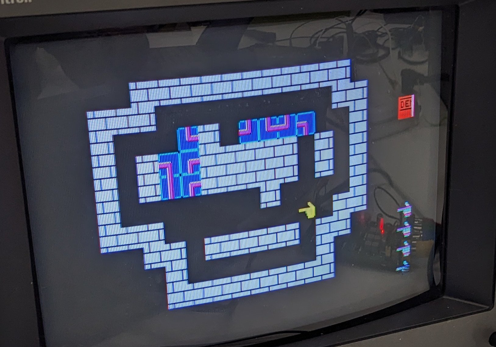
(As you can see, the graphics remain on screen after breaking, and sometimes the listing is difficult to see because of this. The graphics can be cleared by executing INIT “CRT:I” in BASIC, but that will cause rendering of the next level to fail.)

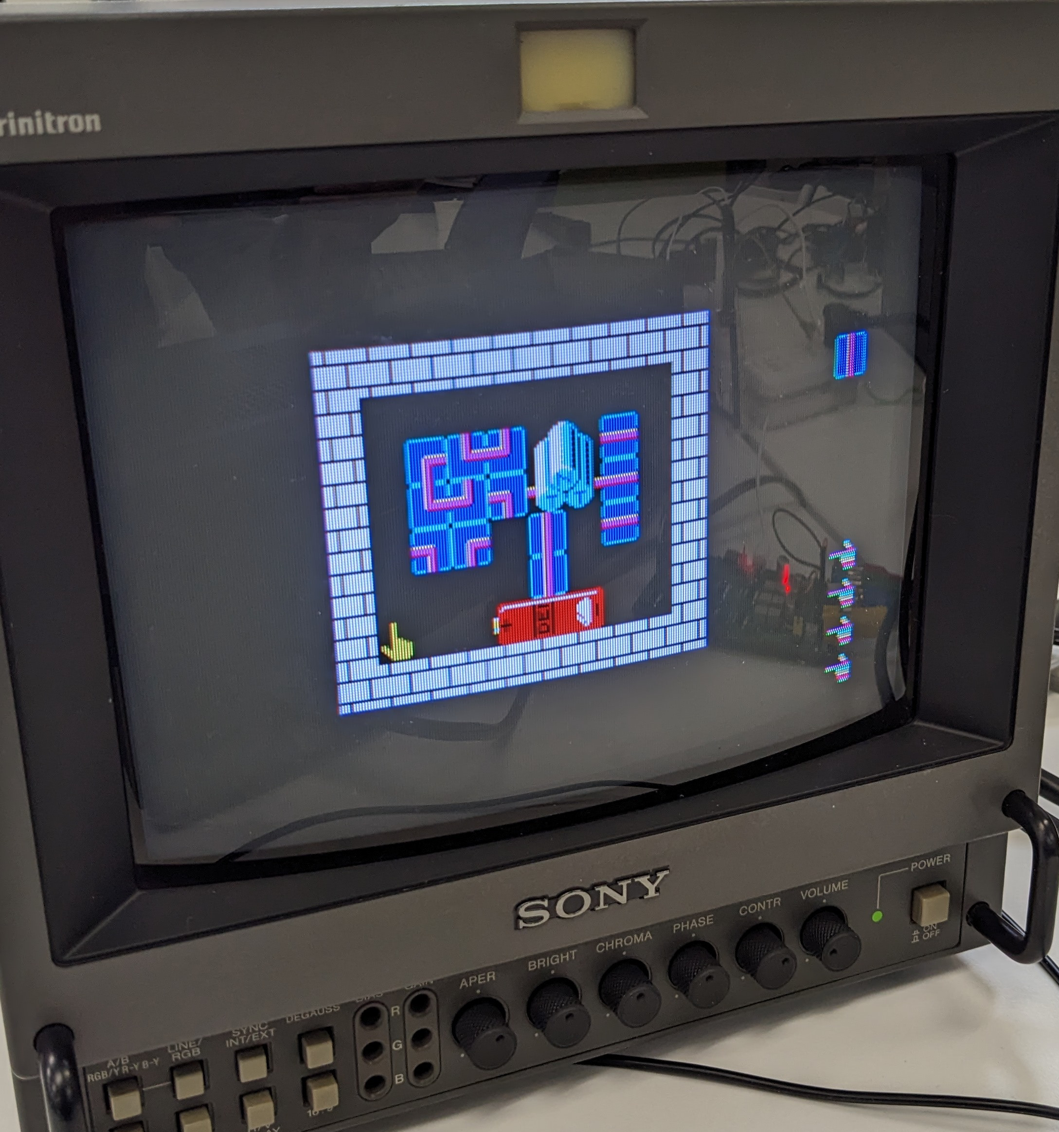
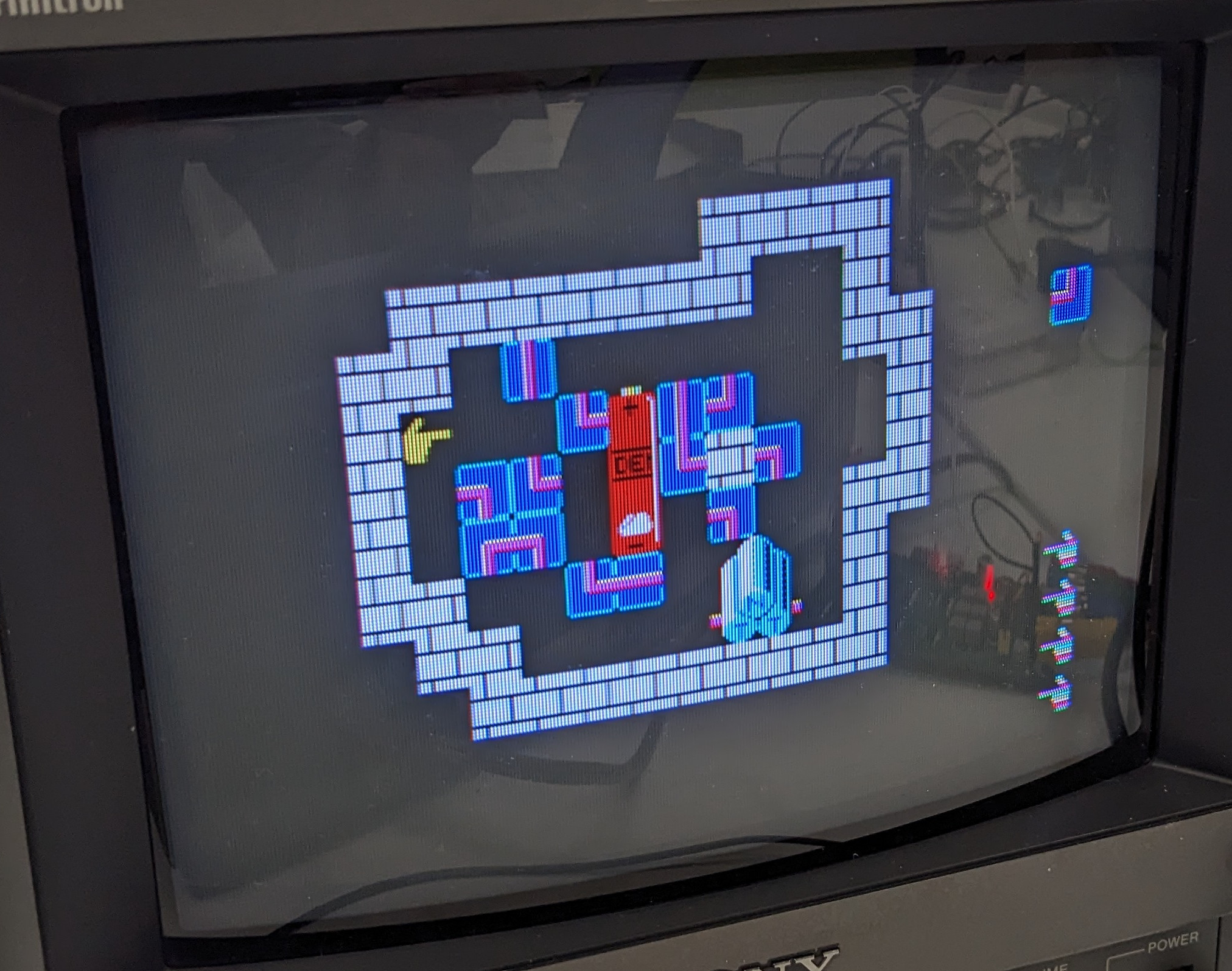
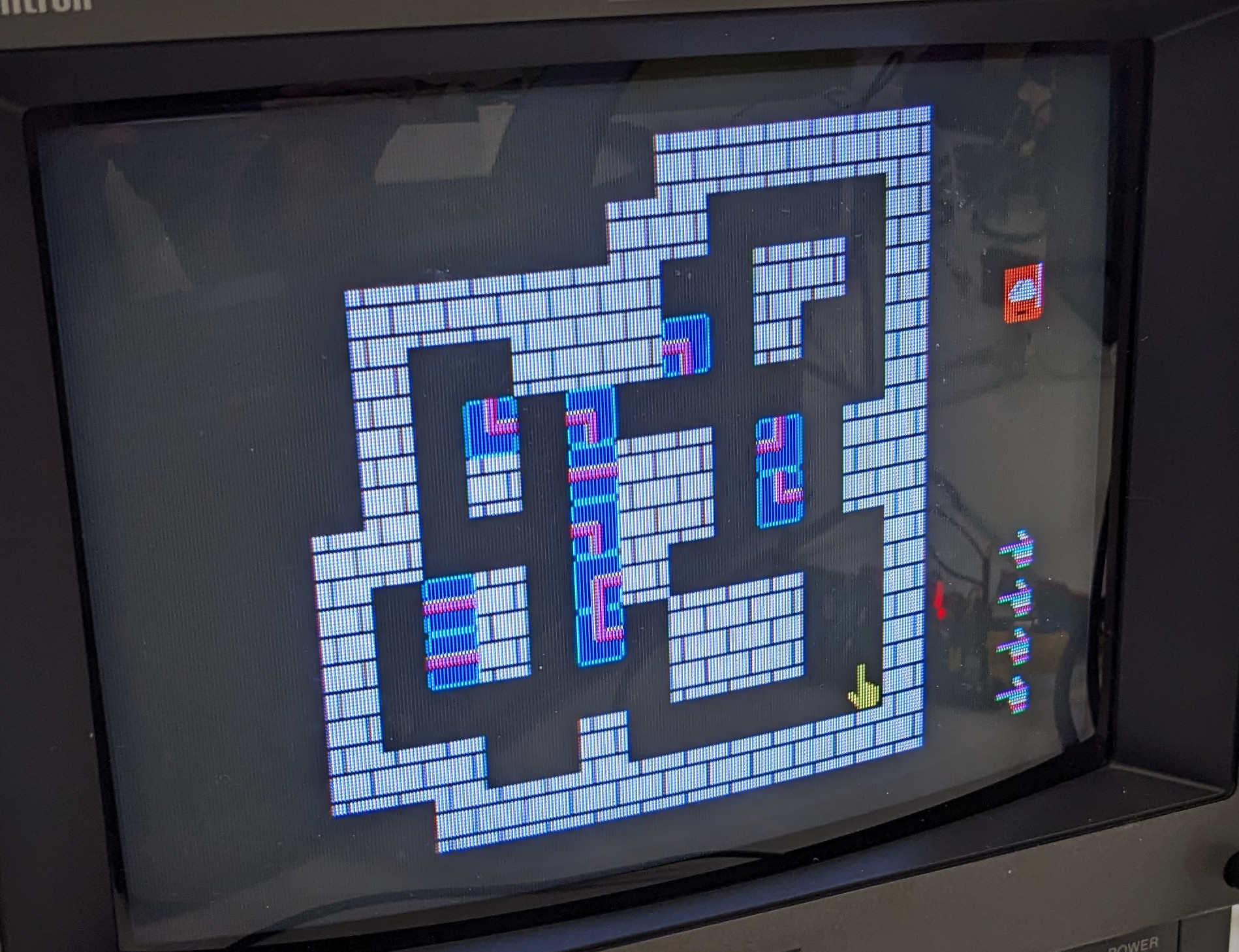
It looked like I got correct views of levels 1-10, and I have added these into my JavaScript clone of the game. Levels 11-20, on the other hand, instead of displaying the level number, displayed a game tile (a wire or part of the battery) inside the upper-right corner of the screen. I have therefore not added these levels to my implementation.

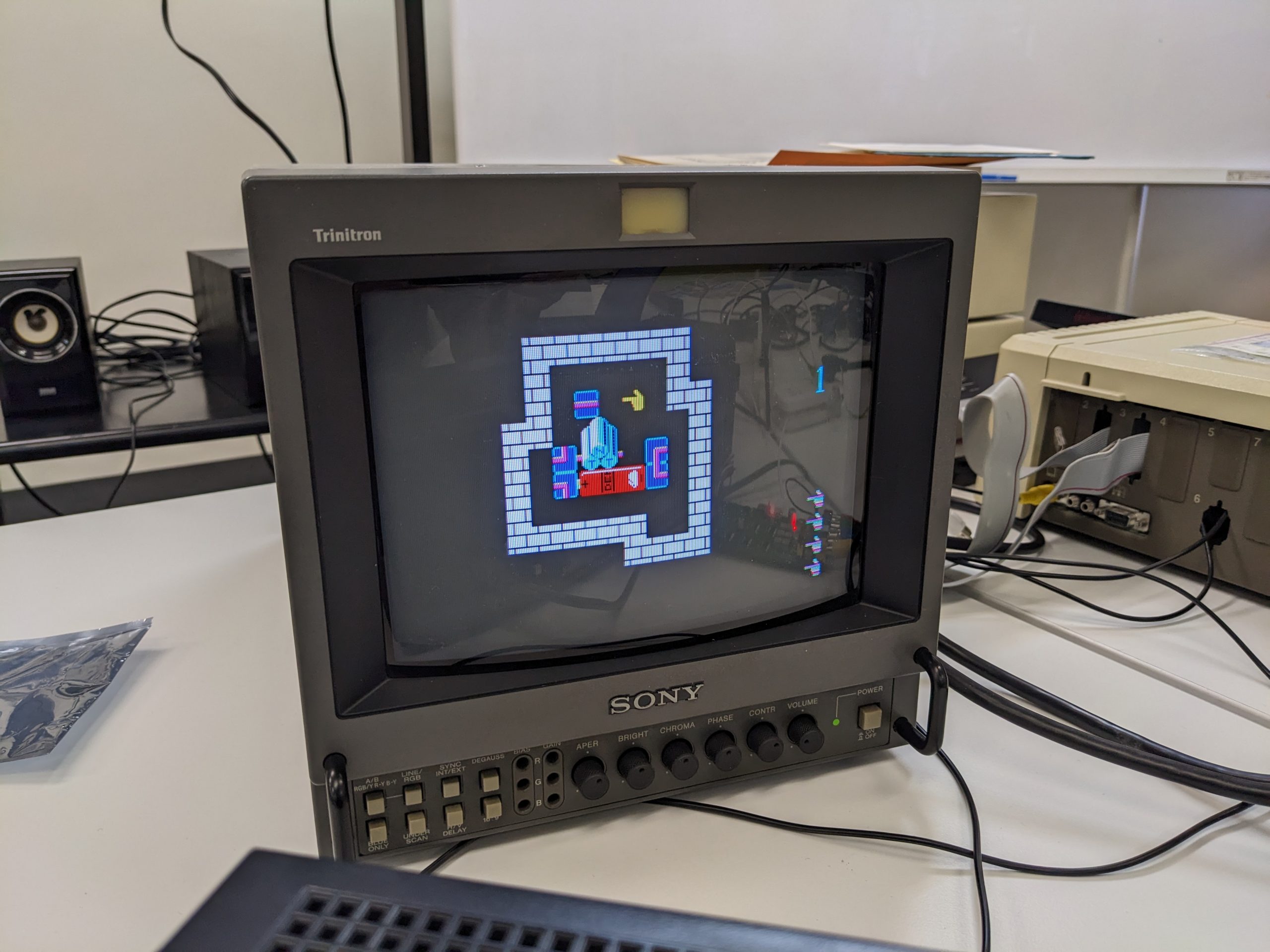
Level 1, original game

My very analog way of copying levels into my clone: 1) look at picture like the one above, 2) type out an array like this:

[
    [ 0, 1, 1, 1, 1, 1, 1, 1, 0, 0 ],
    [ 0, 1, 0, 0, 0, 0, 0, 1, 0, 0 ],
    [ 0, 1, 0, 0, 0, 0, 0, 1, 1, 0 ],
    [ 1, 1, 0, 10, 11, 0, 0, 0, 1, 0 ],
    [ 1, 0, 32, 12, 13, 20, 31, 0, 1, 0 ],
    [ 1, 0, 33, 40, 41, 42, 30, 53, 1, 0 ],
    [ 1, 0, 0, 0, 0, 0, 0, 0, 1, 0 ],
    [ 1, 1, 1, 1, 1, 1, 0, 0, 1, 0 ],
    [ 0, 0, 0, 0, 0, 1, 1, 1, 1, 0 ],
    [ 0, 0, 0, 0, 0, 0, 0, 0, 0, 0 ]
]

(In reality I added the commas after the fact, using a single find and replace operation. I think it took an hour or two for 10 levels.)

The original game has a concept of “lives”, but I don’t think this is a valuable concept in a Sokoban-like game. So I didn’t port that over. In fact, I added functionality to make it easy to go right back to a point you were at before noticing the smell of brain fart. The game is fiendishly difficult in my opinion, I don’t think it’s necessary to make it any more difficult. In fact, if they hadn’t made it so damn difficult, maybe it would be up there with Sokoban and other famous puzzle games from the 1980s.

By the way, I’ve only solved level 1. It was super hard. Update 2023/03/01: And level 2 and 3! It probably took longer to solve level 1 than implementing the basic game logic. No guarantees that levels 2 3 4 and beyond are solvable. If you solve anything beyond level 2 3 4, please send me your sequence strings. I’ll verify them and add a note here or maybe in the game that the level has been shown to be solvable. :)

Making games like this is pretty straightforward, but:

There is one part in my implementation of this game that I think is slightly interesting. Since I do not know the solutions to the puzzles (and there may even be puzzles with multiple solutions), I wrote a small recursive function (trace_wire_path) that traces the electric path and returns true if it leads to the bomb (it starts tracing at a battery terminal). It’s not optimized at all, and I didn’t bother cleaning up the code after getting it to work for the first time (my gut feeling says that it should be easy to replace a lot of the if-thens with lookup tables), but this kind of stuff doesn’t occur too often in regular day-to-day programming, so I thought it was kind of fun. (Though it all depends on what you do for a living, I guess?) Let me know if there’s some corner case where it didn’t work for you. ;)

// for simplicity we always trace from the battery
function trace_wire_path(x, y, dir_x, dir_y) {
    // if tile at x, y is inside ELEMENTS_COMPATIBLE_WITH_POS_DIRX array
    var tile_to_check = levels[current_level][y][x];

    // is this tile compatible with the previous tile?
    if ((dir_x == 1) &&
        (ELEMENTS_COMPATIBLE_WITH_POS_DIRX.indexOf(tile_to_check) == -1))
        return false;
    else if ((dir_x == -1) &&
             (ELEMENTS_COMPATIBLE_WITH_NEG_DIRX.indexOf(tile_to_check) == -1))
        return false;
    else if ((dir_y == 1) &&
             (ELEMENTS_COMPATIBLE_WITH_POS_DIRY.indexOf(tile_to_check) == -1))
        return false;
    else if ((dir_y == -1) &&
             (ELEMENTS_COMPATIBLE_WITH_NEG_DIRY.indexOf(tile_to_check) == -1))
        return false;

    // are we done? (we already know we must be on the right side)
    if ((tile_to_check == TNT_BOTTOM_LEFT) ||
        (tile_to_check == TNT_BOTTOM_RIGHT))
        return true;

    // what's our new direction?
    if ((tile_to_check == HORIZONTAL_WIRE) ||
        (tile_to_check == VERT_WIRE)) {
        new_dir_x = dir_x;
        new_dir_y = dir_y;
    } else if ((tile_to_check == CORNER_WIRE_NW) ||
                (tile_to_check == CORNER_WIRE_SW) ||
                (tile_to_check == CORNER_WIRE_NE) ||
                (tile_to_check == CORNER_WIRE_SE)) {
        if (dir_x) { // dir_x is 1 or -1
            new_dir_x = 0;
            if ((tile_to_check == CORNER_WIRE_NW) ||
                (tile_to_check == CORNER_WIRE_NE))
                new_dir_y = -1; // up
            else if ((tile_to_check == CORNER_WIRE_SW) ||
                     (tile_to_check == CORNER_WIRE_SE))
                new_dir_y = 1; // down
        } else { // dir_x is 0
            new_dir_y = 0;
            if ((tile_to_check == CORNER_WIRE_NW) ||
                (tile_to_check == CORNER_WIRE_SW))
                new_dir_x = -1;
            else if ((tile_to_check == CORNER_WIRE_NE) ||
                     (tile_to_check == CORNER_WIRE_SE))
                new_dir_x = 1;
        }
    }

    // recurse
    return trace_wire_path(x+new_dir_x, y+new_dir_y, new_dir_x, new_dir_y);
}

Performance

It shouldn’t be a big deal to leave this game open in a tab somewhere. Virtually no CPU and not a lot of memory should be in use when nothing is happening. about:performance snapshot with the game just sitting there, waiting for user input:

No quantifiable energy impact; memory is low too.

In case anyone wants pictures of levels 11-20, which I haven’t included in my clone because they looked a bit suspicious:

11
12
13
14
15
16
17
18
19
20

Yeah, I don’t quite get why the battery isn’t inside the playfield, and there’s no TNT either… If anyone wants to convert these levels into my format, patches are welcome. :)

Copyrights

Copyright status of my clone: I recreated the original graphics in Inkscape. I do not claim any copyright on the graphics. As they are recreated somewhat faithfully, the graphics probably are technically pirated and not copyrightable. The code may or may not be copyrightable. If it is, let’s say it’s GPLv3 for now. However, I disclaim all copyright after release + 15 years.

Lowering the footprint of JT51 (YM2151 Verilog clone) to work on smaller FPGAs, specifically the ICE40UP5K (Part 1? WIP? Progress diary?) / UPduino mini-tutorial

Update 2023/03/09

I will upload the changes necessary to run the JT51 as a drop-in replacement of a real YM2151 relatively soon. Things aren’t 100% ironed out yet.

Update 2023/03/06

The below update states that there are errors in jt51_phrom and jt51_exprom.v, but these errors were minor and have been fixed. However, the fixed jt51_phrom.v doesn’t appear to have a large effect on the final number of LUT4s used. It looks like the mistake I had originally made (a race condition-type of mistake) was responsible for the majority of the savings. Boo.

Here’s a short sound recording with the mistake left in:

And here’s a short sound recording with the mistake ironed out:

In addition, the changes to jt51_sh.v mentioned in the below update might suffer from some problems too. So far I have only managed to run with jt51_sh8 enabled, so I have no way to compare the unmodified jt51_sh implementation to my modified implementation, but I also tried adding jt51_sh10 for another shift register, and that made things sound rather weird. It’s currently not clear to me why that is the case.

Important update 2023/03/01

I finally managed to test the modified code. Do not use it, there are probably errors in it. Using the modified sine tables (jt51_phrom.v) causes everything to sound noisy. Using the modified exprom.v messes something up, but the effect is rather subtle.

Instead, you can save on LUTs by modifying jt51_sh.v as follows. This is the original code:

module jt51_sh #(parameter width=5, stages=32, rstval=1'b0 ) (
    input                           rst,
    input                           clk,
    input                           cen,
    input       [width-1:0]         din,
    output      [width-1:0]         drop
);

reg [stages-1:0] bits[width-1:0];

genvar i;
generate
    for (i=0; i < width; i=i+1) begin: bit_shifter
        always @(posedge clk, posedge rst) begin
            if(rst)
                bits[i] <= {stages{rstval}};
            else if(cen)
                bits[i] <= {bits[i][stages-2:0], din[i]};
        end
        assign drop[i] = bits[i][stages-1];
    end
endgenerate

endmodule

It looks like the logic yosys synthesizes from this code is inefficient. I haven’t looked too much into it, but writing this code out (and removing one of the channels, etc.) causes yosys to synthesize more efficient code. As you can see, this code uses parameters that affect the way it is generated. I just picked one set of parameters that appeared multiple times, width=14 and stages=8, and that was enough to get the logic to just fit. I.e., I appended the following code inside the same file:

module jt51_sh8 #(parameter rstval=1'b0 ) (
    input                           rst,
    input                           clk,
    input                           cen,
    input       [13:0]         din,
    output      [13:0]         drop
);

reg [7:0] bits[13:0];

// jt51_sh #( .width(14), .stages(8)) prev1_buffer(
// reg [7:0] bits[13:0]

genvar i;
// generate
//     for (i=0; i < 14; i=i+1) begin: bit_shifter
//         always @(posedge clk, posedge rst) begin
//             if(rst)
//                 bits[i] <= {8{rstval}};
//             else if(cen)
//                 bits[i] <= {bits[i][6:0], din[i]};
//         end
//         assign drop[i] = bits[i][7];
//     end
// endgenerate
        always @(posedge clk, posedge rst) begin
            if(rst) begin
                bits[0] <= {8{rstval}};
                bits[1] <= {8{rstval}};
                bits[2] <= {8{rstval}};
                bits[3] <= {8{rstval}};
                bits[4] <= {8{rstval}};
                bits[5] <= {8{rstval}};
                bits[6] <= {8{rstval}};
                bits[7] <= {8{rstval}};
                bits[8] <= {8{rstval}};
                bits[9] <= {8{rstval}};
                bits[10] <= {8{rstval}};
                bits[11] <= {8{rstval}};
                bits[12] <= {8{rstval}};
                bits[13] <= {8{rstval}};
            end
            else if(cen) begin
                bits[0] <= {bits[0][6:0], din[0]};
                bits[1] <= {bits[1][6:0], din[1]};
                bits[2] <= {bits[2][6:0], din[2]};
                bits[3] <= {bits[3][6:0], din[3]};
                bits[4] <= {bits[4][6:0], din[4]};
                bits[5] <= {bits[5][6:0], din[5]};
                bits[6] <= {bits[6][6:0], din[6]};
                bits[7] <= {bits[7][6:0], din[7]};
                bits[8] <= {bits[8][6:0], din[8]};
                bits[9] <= {bits[9][6:0], din[9]};
                bits[10] <= {bits[10][6:0], din[10]};
                bits[11] <= {bits[11][6:0], din[11]};
                bits[12] <= {bits[12][6:0], din[12]};
                bits[13] <= {bits[13][6:0], din[13]};
            end
        end
        assign drop[0] = bits[0][7];
        assign drop[1] = bits[0][7];
        assign drop[2] = bits[0][7];
        assign drop[3] = bits[0][7];
        assign drop[4] = bits[0][7];
        assign drop[5] = bits[0][7];
        assign drop[6] = bits[0][7];
        assign drop[7] = bits[0][7];
        assign drop[8] = bits[0][7];
        assign drop[9] = bits[0][7];
        assign drop[10] = bits[0][7];
        assign drop[11] = bits[0][7];
        assign drop[12] = bits[0][7];
        assign drop[13] = bits[0][7];
endmodule

And adjusted jt51_op.v to use jt51_sh8 instead of jt51_sh for prev1_buffer, prevprev1_buffer, and prev2_buffer.

Original post follows:

Quick summary

I took JT51 (https://github.com/jotego/jt51) and shrunk it down a little. I got it down to just barely fit. There are some lookup tables that are processed down by a couple hundred LUT4s, I made the lookup tables contain the already processed values instead. We’re now using slightly more RAM.

How we got here

I am currently debugging a YM2151-based device, the Yamaha SFG-01 sound module for MSX PCs. There is… wonky audio when two notes are played at once on the attached keyboard. I started off by emulating the YM3012 DAC on a Raspberry Pi Pico. More on that in a future post. More on the whole repair in a future post, in fact. My plan was to run the original YM2151 and the FPGA version side-by-side (with the exact same inputs) and to compare the audio outputs. However, after I already did most things detailed in this post, I realized that plan probably wasn’t going to work, as (if I read the datasheet correctly) the YM2151 generates interrupts which probably have to be acknowledged, and the data bus is bidirectional, and actually does get read out by the CPU occasionally. So the original chip and the FPGA would have to work in 100% perfect sync, and who knows how achievable that is.

I have two FPGA boards, and they’re both exactly the same, UPduino v3.0. I bought these back in 2020 or so, expecting I’d maybe come up with a project at some point. They were cheaper back then! I paid 43.20 USD + 6 USD shipping for 2! So per device, in JPY at that time: 21.6 * 103 = 2225 JPY. Currently, the price is $30 per device, and USD/JPY is 133.8. 30 * 133.8 = 4014 JPY, so almost double. Yikes.

Only have an ICE40UP3K? Allegedly, if you use the open-source toolchain, it’ll have exactly the same amount of LUT4s available as an ICE40UP5K. Apparently it’s just the official IDE enforcing an artificial limit?

So all I’d done up to this point was: I installed the open-source toolchain, changed the speed of the LED blinking example, re-flashed, and got some satisfaction that it all worked. Let’s start from that point. I think the official tutorials should get you there (except for the speed change maybe).

Also: important: I haven’t tested my revised Verilog yet. That’s something for part 2 (not done/written yet).

Going beyond the rgb_blink example

This is the first time I’m compiling feral Verilog code for this board, so I took notes along the way. This blog post is just what I’d written down, just polished a little. First of all, make sure you can compile and flash the rgb_blink example. Follow the documentation, at the very least https://upduino.readthedocs.io/en/latest/getting_started/tool_installation.html and https://upduino.readthedocs.io/en/latest/tutorials/blink_led.html.

Then, git clone https://github.com/jotego/jt51. Copy UPduino-v3.0/RTL/common from the toolchain to jt51/ and UPduino-v3.0/RTL/blink_led/Makefile to jt51/hdl/. Perhaps cd to jt51/hdl and modify the Makefile as follows.

Note: Makefiles consist of rules laying out how to build a certain file. Rule blocks start like this: “filename: dependencies”. The dependencies are filenames. There is only one rule in our Makefile that directly depends on .v files:

rgb_blink.json: rgb_blink.v

Instead of rgb_blink.v, we’ll replace that by all the jt51_….v files we have in jt51/hdl:

jt51_acc.v jt51_csr_ch.v jt51_csr_op.v jt51_eg.v jt51_exp2lin.v jt51_exprom.v jt51_kon.v jt51_lfo.v jt51_lin2exp.v jt51_mmr.v jt51_mod.v jt51_noise_lfsr.v jt51_noise.v jt51_op.v jt51_pg.v jt51_phinc_rom.v jt51_phrom.v jt51_pm.v jt51_reg.v jt51_sh.v jt51_timers.v jt51.v

Then also change the vosys command to synthesize from these .v files instead of rgb_blink.v:

yosys -q -p "synth_ice40 -json rgb_blink.json" jt51_acc.v jt51_csr_ch.v jt51_csr_op.v jt51_eg.v jt51_exp2lin.v jt51_exprom.v jt51_kon.v jt51_lfo.v jt51_lin2exp.v jt51_mmr.v jt51_mod.v jt51_noise_lfsr.v jt51_noise.v jt51_op.v jt51_pg.v jt51_phinc_rom.v jt51_phrom.v jt51_pm.v jt51_reg.v jt51_sh.v jt51_timers.v jt51.v

And finally, let’s change all names from “rgb_blink” to “jt51” using search and replace: “rgb_blink” -> “jt51”. You should end up with a Makefile like this:

# Makefile to build UPduino v3.0 rgb_blink.v  with icestorm toolchain
# Original Makefile is taken from: 
# https://github.com/tomverbeure/upduino/tree/master/blink
# On Linux, copy the included upduinov3.rules to /etc/udev/rules.d/ so that we don't have
# to use sudo to flash the bit file.
# Thanks to thanhtranhd for making changes to thsi makefile.

rgb_blink.bin: rgb_blink.asc
	icepack rgb_blink.asc rgb_blink.bin

rgb_blink.asc: rgb_blink.json ../common/upduino.pcf
	nextpnr-ice40 --up5k --package sg48 --json rgb_blink.json --pcf ../common/upduino.pcf --asc rgb_blink.asc   # run place and route

rgb_blink.json: rgb_blink.v
	yosys -q -p "synth_ice40 -json rgb_blink.json" rgb_blink.v

.PHONY: flash
flash:
	iceprog -d i:0x0403:0x6014 rgb_blink.bin

.PHONY: clean
clean:
	$(RM) -f rgb_blink.json rgb_blink.asc rgb_blink.bin

Make sure you have tab characters, not space characters in the rule block indentation. (Trap for young players.) Make sure you also copied the common/ directory as instructed above. Then, execute “make”. If you get the following error:

$ make
nextpnr-ice40 --up5k --package sg48 --json jt51.json --pcf ../common/upduino.pcf --asc jt51.asc   # run place and route
/bin/sh: 1: nextpnr-ice40: not found
make: *** [Makefile:12: jt51.asc] Error 127

That means you need nextpnr-ice40 in your PATH. Figure out the path, and then execute:

PATH=$PATH:/path/to/directory/containing/nextpnr-ice40

Next, you should get the following error:

$ make
nextpnr-ice40 --up5k --package sg48 --json jt51.json --pcf ../common/upduino.pcf --asc jt51.asc   # run place and route
ERROR: IO 'xright[15]' is unconstrained in PCF (override this error with --pcf-allow-unconstrained)
ERROR: Loading PCF failed.
0 warnings, 2 errors
make: *** [Makefile:12: jt51.asc] Error 255

For now, override this error as instructed, by changing the nextpnr-ice40 command in the Makefile as follows:

nextpnr-ice40 --up5k --package sg48 --json jt51.json --pcf ../common/upduino.pcf --asc jt51.asc --pcf-allow-unconstrained

At this point we’ll finally get some actually interesting error output.

As-is, the project doesn’t fit on the ICE40

...
Info: Device utilisation:
Info:            ICESTORM_LC:  6680/ 5280   126%
Info:           ICESTORM_RAM:     6/   30    20%
Info:                  SB_IO:    91/   96    94%
Info:                  SB_GB:     8/    8   100%
Info:           ICESTORM_PLL:     0/    1     0%
Info:            SB_WARMBOOT:     0/    1     0%
Info:           ICESTORM_DSP:     0/    8     0%
Info:         ICESTORM_HFOSC:     0/    1     0%
Info:         ICESTORM_LFOSC:     0/    1     0%
Info:                 SB_I2C:     0/    2     0%
Info:                 SB_SPI:     0/    2     0%
Info:                 IO_I3C:     0/    2     0%
Info:            SB_LEDDA_IP:     0/    1     0%
Info:            SB_RGBA_DRV:     0/    1     0%
Info:         ICESTORM_SPRAM:     0/    4     0%

Info: Placed 0 cells based on constraints.
ERROR: Unable to place cell '$abc$113462$auto$blifparse.cc:492:parse_blif$114175_LC', no BELs remaining to implement cell type 'ICESTORM_LC'
91 warnings, 1 error
make: *** [Makefile:13: jt51.asc] Error 255

Okay, first things first. How old is our toolchain?

$ yosys -V
Yosys 0.8 (git sha1 5706e90)

Let’s see, the newest version of yosys, at the time of this writing, is… 0.26. Wait what? Ah, it looks like a smaller number, but is probably intended to be a larger number. It appears that my version is from 2018. Likely, I’d just installed it from Debian’s repositories. Let’s try building yosys from Git so we can upgrade from 0.8 to 0.26. It would like to build using clang by default, but you can build using gcc too. You also need tcl8.6-dev (or probably other versions work fine too).

$ git clone https://github.com/YosysHQ/yosys
$ cd yosys
$ make
/bin/sh: 1: clang: not found
[  0%] Building kernel/version_4c334b905.cc
[  0%] Building kernel/version_4c334b905.o
/bin/sh: 1: clang: not found
make: *** [Makefile:754: kernel/version_4c334b905.o] Error 12
$ make config-gcc
...
In file included from kernel/calc.cc:24:
./kernel/yosys.h:81:12: fatal error: tcl.h: No such file or directory
 #  include <tcl.h>
...
$ sudo apt-get install tcl8.6-dev
...
$ make config-gcc
...
$ # success

And if we try synthesizing again now, we do get a significant improvement. (Also synthesis time is faster I think.) But we are not quite there yet:

Info: Device utilisation:
Info:            ICESTORM_LC:  5836/ 5280   110%
Info:           ICESTORM_RAM:     3/   30    10%
Info:                  SB_IO:    91/   96    94%
Info:                  SB_GB:     8/    8   100%
Info:           ICESTORM_PLL:     0/    1     0%
Info:            SB_WARMBOOT:     0/    1     0%
Info:           ICESTORM_DSP:     0/    8     0%
Info:         ICESTORM_HFOSC:     0/    1     0%
Info:         ICESTORM_LFOSC:     0/    1     0%
Info:                 SB_I2C:     0/    2     0%
Info:                 SB_SPI:     0/    2     0%
Info:                 IO_I3C:     0/    2     0%
Info:            SB_LEDDA_IP:     0/    1     0%
Info:            SB_RGBA_DRV:     0/    1     0%
Info:         ICESTORM_SPRAM:     0/    4     0%

Shrinking the footprint by changing yosys options (using DSP cells)

110% isn’t too far from where we need to be, so let’s investigate if we can do anything to reduce our FPGA footprint. First of all, there are three files that include the word ‘rom’, which may have a significant effect on our footprint. But it looks like our toolchain is clever — it actually uses ICESTORM_RAM to implement the ROM. (Replacing the entire case/endcase block in the rather large jt51_phinc_rom.v file with a single statement reduced the LC count by 2-3%, and ICESTORM_RAM from 10% to 0%.)

Next, we forget about yosys for a second, and attempt to synthesize this using the official toolchain from Lattice, IceCube2. You’ll need an account and follow a link to generate a license file. You need to enter a MAC address to bind the license to a certain computer. (Or maybe a computer with a certain network adapter.)

IceCube2’s synthesis finishes in a few seconds, and only uses 11 logic cells. Hmm, so efficient! Or more likely, something’s weird. And yes, indeed it’s getting confused and thinks that jt51_noise_lfsr.v is the main file. Apparently, this file’s modules aren’t actually used anywhere. So we get rid of that file (and also get rid of it in our Makefile above) and re-synthesize. Synthesis finishes successfully, and apparently uses 1698 LUTs. Hmm, really? (No, but let me go off a quick tangent first.)

Okay, let’s assume for a second that yosys is much, much worse than IceCube2. It’s time to google for something like ‘yosys vs icecube2’. A person on the EEVblog forums says, “The IceCube2 generates smaller and faster design (most visible with larger designs) than the IceStorm does, it can infer ie. multipliers with built-in DSP modules (UP5k) etc. The IceStorm is less effective, and infers ie. multipliers in fabric (you have to instantiate the modules/primitives manually).” Hmm, interesting. Well, it turns out you can enable the DSP modules in yosys using the -dsp option, so we modify the Makefile as follows:

yosys -q -p "synth_ice40 -dsp -json jt51.json" jt51_acc.v jt51_csr_ch.v jt51_csr_op.v jt51_eg.v jt51_exp2lin.v jt51_exprom.v jt51_kon.v jt51_lfo.v jt51_lin2exp.v jt51_mmr.v jt51_mod.v jt51_noise.v jt51_op.v jt51_pg.v jt51_phinc_rom.v jt51_phrom.v jt51_pm.v jt51_reg.v jt51_sh.v jt51_timers.v jt51.v

That reduces our LUT count by ~2% percent. Every percent counts, but we’re not quite there yet. Looking at https://github.com/YosysHQ/yosys/blob/master/techlibs/ice40/synth_ice40.cc, we see a few more options we could try, e.g., -spram, -noabc, -abc2, -abc9 (experimental), -flowmap (experimental).

-noabc brings us back up to 120%. -flowmap also increases the number of logic cells to a similar number. -abc2 eliminates 19 logic cells vs. just -abc, but that’s not a lot, and our percentage doesn’t change. -abc9 doesn’t yield much of an improvement either. Hmm, looks like we’ve exhausted some of the lower hanging fruit. Anyway, let’s take another closer look at the official toolchain’s output. When your eyes get a little more used to its output you actually notice that it says:

Cell usage:
GND             39 uses
SB_CARRY        366 uses
SB_DFF          22 uses
SB_DFFE         276 uses
SB_DFFER        2709 uses
SB_DFFES        747 uses
SB_DFFESR       8 uses
SB_DFFESS       10 uses
SB_DFFR         29 uses
SB_DFFS         1 use
SB_DFFSR        23 uses
SB_GB           3 uses
SB_RAM1024x4    3 uses
VCC             39 uses
SB_MAC16        2 uses
    MULTONLY    1 use
    MULTADD     1 use
SB_LUT4         1698 uses

Hey. 1698 LUTs, but 3825 DFFs, and the P&R Flow tool confirms this:

Number of LUTs      :   1698
Number of DFFs      :   3825
Number of Carrys    :   366

These DFFs also use up LUTs, so the total number of LUTs used is 5523, which is actually extremely close to yosys, and also too much. (Note that I already edited the Verilog a little bit at this point, so the number on an unmodified repository would be a little higher.)

Let’s remove the -q option from yosynth’s synth_ice40 command in the Makefile, and take a look at the output close to the summary that we looked at before. Scrolling way past a lot of verbose output, we get a summary like the following, and can see that yosys is indeed very close.

Info: Packing constants..
Info: Packing IOs..
Info: Packing LUT-FFs..
Info:     1462 LCs used as LUT4 only
Info:      515 LCs used as LUT4 and DFF
Info: Packing non-LUT FFs..
Info:     3367 LCs used as DFF only
Info: Packing carries..
Info:      184 LCs used as CARRY only
Info: Packing indirect carry+LUT pairs...
Info:       63 LUTs merged into carry LCs

Shrinking the footprint by removing features

Next, we could try and cut down on features in order to reduce the required number of logic cells. First of all, I nuked the entire right channel (“right” and “xright”) by commenting out a couple lines in jt51.v and jt51_acc.v. That shaved off about 2%. I kept “xleft” but also got rid of the converted “left”. That means we no longer need to compile jt51_exp2lin.v, which seems to save 9 LUTs.

Shrinking the footprint by trading LUTs for RAM

A cursory (liar liar pants on fire) glance over the code revealed an opportunity to potentially save a more significant number of LUTs. In jt51_op.v, we refer to a sine table (which is in jt_phrom.v) and concatenate certain bits from this table. In the following snippet, the sine table is already in the sta_XI register:

case( phaselo_XI[7:6] )
    2'b00: stb = { 10'b0, sta_XI[29], sta_XI[25], 2'b0, sta_XI[18], 
        sta_XI[14], 1'b0, sta_XI[7] , sta_XI[3] };
    2'b01: stb = { 6'b0 , sta_XI[37], sta_XI[34], 2'b0, sta_XI[28], 
        sta_XI[24], 2'b0, sta_XI[17], sta_XI[13], sta_XI[10], sta_XI[6], sta_XI[2] };
    2'b10: stb = { 2'b0, sta_XI[43], sta_XI[41], 2'b0, sta_XI[36],
        sta_XI[33], 2'b0, sta_XI[27], sta_XI[23], 1'b0, sta_XI[20],
        sta_XI[16], sta_XI[12], sta_XI[9], sta_XI[5], sta_XI[1] };
    2'b11: stb = {
            sta_XI[45], sta_XI[44], sta_XI[42], sta_XI[40]
        , sta_XI[39], sta_XI[38], sta_XI[35], sta_XI[32]
        , sta_XI[31], sta_XI[30], sta_XI[26], sta_XI[22]
        , sta_XI[21], sta_XI[19], sta_XI[15], sta_XI[11]
        , sta_XI[8], sta_XI[4], sta_XI[0] };
    default: stb = 19'dx;

If you are new to Verilog, numbers often look like this: <total bit width>'<letter indicating number format, e.g., b for binary><number>. The array indices refer to bit numbers. E.g., sta_XI[38] is bit 38 in sta_XI, counting from 0. “case” is like a switch statement in C. So up here, we do something like:

switch(bits 7 and 6 of phaselo_XI) {
    case 0: ...;
    case 1: ...;
    case 2: ...;
    case 3: ...;
    default: ...;
}

(The “default” clause is extraneous, but doesn’t cause harm.)

The sine table is fairly large, at 32 entries of 46 bits. In the above code snippet, we pick (to me, super random) bits from the table and also insert constant 0s and 1s here and there. E.g., the first line reads in plain words: ten 0s, followed by sinetable[i][29], followed by sinetable[i][25], followed by two 0s, etc. The sine table isn’t used anywhere else.

Our opportunity is: instead of generating a circuit to combine bits from the sinetable together, we can just rewrite the sine lookup table to already contain what we call stb above. It doesn’t matter if our table ends up a little larger (it could be up to four times larger), because as mentioned above, RAM is used to store these tables. But our table isn’t that much larger, really. Before we had 32×46=1472 bits, now we have a three-dimensional array of dimensions 4x32x19=2432 bits, not even twice as large.

This optimization takes us to 5363/5280 (101%), which means we’re almost done! (If we use four two-dimensional arrays and a case block, the savings are much less pronounced, 104%.) Of course, there is no free lunch: we now use more RAM: ICESTORM_RAM 5/30 (16%). Before it was 3/30 (10%). But we still have a lot of RAM left.

Rewriting the table by hand presumably gets old quickly, so I wrote a short Perl script to do it. (Luckily, it can sometimes be very easy to transform Verilog source code to Perl using find and replace with regular expressions.)

#!/usr/bin/perl

$sta_XI = [[0, 0, 0, 1, 1, 0, 0, 0, 0, 0, 1, 0, 0, 1, 0, 0, 0, 1, 0, 0, 0, 1, 0, 0, 0, 0, 1, 0, 1, 0, 1, 0, 1, 0, 1, 0, 1, 0, 0, 1, 0, 1, 0, 0, 1, 0],
    [0, 0, 0, 1, 1, 0, 0, 0, 0, 0, 1, 1, 0, 1, 0, 0, 0, 0, 0, 1, 0, 0, 0, 0, 0, 0, 1, 0, 0, 1, 0, 0, 0, 1, 0, 0, 1, 1, 0, 1, 0, 0, 0, 0, 0, 1],
    [0, 0, 0, 1, 1, 0, 0, 0, 0, 0, 1, 1, 0, 1, 0, 0, 0, 0, 0, 1, 0, 0, 1, 1, 0, 0, 1, 0, 0, 0, 1, 0, 1, 1, 0, 0, 1, 1, 0, 1, 1, 0, 0, 0, 0, 0],
    [0, 0, 0, 1, 1, 1, 0, 0, 0, 0, 0, 1, 0, 0, 0, 0, 0, 0, 0, 0, 0, 0, 1, 1, 0, 0, 1, 0, 1, 1, 0, 0, 0, 1, 0, 0, 1, 1, 0, 1, 1, 1, 0, 0, 1, 0],
    [0, 0, 0, 1, 1, 1, 0, 0, 0, 0, 0, 1, 0, 0, 0, 0, 0, 0, 1, 1, 0, 0, 0, 0, 0, 0, 1, 0, 1, 1, 1, 0, 1, 0, 0, 0, 1, 1, 0, 1, 1, 0, 1, 0, 0, 1],
    [0, 0, 0, 1, 1, 1, 0, 0, 0, 0, 0, 1, 0, 1, 0, 0, 0, 0, 1, 0, 0, 1, 1, 0, 0, 0, 1, 0, 0, 0, 0, 0, 0, 0, 1, 0, 1, 1, 0, 1, 1, 1, 1, 0, 1, 0],
    [0, 0, 0, 1, 1, 1, 0, 0, 0, 0, 0, 1, 0, 1, 0, 0, 0, 0, 1, 1, 0, 1, 1, 0, 0, 0, 1, 0, 0, 1, 0, 0, 1, 1, 0, 0, 1, 1, 0, 1, 0, 1, 1, 0, 1, 0],
    [0, 0, 0, 1, 1, 1, 0, 0, 0, 0, 0, 1, 1, 1, 0, 0, 0, 0, 0, 1, 0, 1, 0, 1, 0, 0, 1, 0, 1, 1, 1, 0, 0, 0, 1, 0, 1, 1, 1, 1, 1, 1, 1, 1, 0, 0],
    [0, 0, 0, 1, 1, 1, 0, 0, 0, 0, 1, 1, 1, 0, 0, 0, 0, 0, 0, 0, 0, 1, 1, 1, 0, 0, 1, 0, 1, 0, 1, 1, 1, 0, 0, 0, 1, 1, 0, 1, 1, 1, 0, 1, 1, 1],
    [0, 0, 0, 1, 1, 1, 0, 0, 0, 0, 1, 1, 1, 0, 0, 0, 0, 1, 0, 1, 0, 0, 1, 1, 1, 0, 0, 0, 0, 1, 1, 1, 0, 1, 0, 1, 1, 0, 1, 0, 1, 0, 0, 1, 1, 0],
    [0, 0, 0, 1, 1, 1, 0, 0, 0, 0, 1, 1, 1, 1, 0, 0, 0, 1, 1, 0, 0, 0, 0, 1, 1, 0, 0, 0, 1, 1, 1, 1, 0, 0, 0, 0, 1, 0, 0, 1, 1, 1, 1, 0, 1, 0],
    [0, 0, 0, 1, 1, 1, 0, 0, 0, 0, 1, 1, 1, 1, 0, 0, 0, 1, 1, 1, 0, 0, 1, 1, 1, 0, 0, 1, 1, 0, 1, 0, 1, 1, 0, 0, 1, 0, 0, 1, 1, 1, 0, 1, 1, 1],
    [0, 1, 0, 0, 1, 0, 0, 0, 0, 1, 0, 1, 0, 0, 0, 0, 0, 1, 0, 0, 0, 1, 0, 1, 1, 0, 0, 1, 0, 0, 1, 0, 0, 0, 1, 1, 1, 0, 1, 0, 1, 1, 0, 1, 1, 1],
    [0, 1, 0, 0, 1, 0, 0, 0, 0, 1, 0, 1, 0, 1, 0, 0, 0, 1, 0, 0, 0, 1, 0, 0, 1, 0, 0, 1, 1, 1, 0, 0, 0, 1, 1, 1, 1, 1, 0, 0, 1, 0, 1, 0, 1, 0],
    [0, 1, 0, 0, 1, 0, 0, 0, 0, 1, 0, 1, 0, 1, 0, 0, 0, 1, 0, 1, 0, 1, 1, 0, 1, 1, 0, 1, 1, 1, 1, 1, 1, 0, 1, 0, 0, 1, 0, 1, 0, 0, 0, 1, 1, 0],
    [0, 1, 0, 0, 1, 0, 0, 0, 1, 1, 1, 0, 0, 0, 0, 0, 0, 0, 1, 0, 0, 0, 0, 1, 1, 0, 0, 1, 0, 1, 0, 1, 1, 0, 1, 0, 1, 1, 0, 1, 1, 1, 1, 0, 0, 1],
    [0, 1, 0, 0, 1, 0, 0, 0, 1, 1, 1, 0, 0, 1, 0, 0, 0, 0, 1, 0, 0, 0, 1, 0, 1, 0, 1, 1, 1, 0, 0, 1, 0, 1, 0, 0, 1, 0, 1, 1, 1, 0, 1, 1, 1, 1],
    [0, 1, 0, 0, 1, 0, 0, 0, 1, 1, 1, 0, 1, 1, 0, 0, 0, 0, 0, 1, 1, 1, 0, 1, 1, 0, 1, 0, 0, 0, 0, 0, 0, 1, 0, 1, 1, 0, 1, 0, 1, 1, 0, 0, 0, 1],
    [0, 1, 0, 0, 1, 1, 0, 0, 1, 1, 0, 0, 1, 0, 0, 0, 0, 0, 0, 1, 1, 1, 1, 0, 1, 0, 1, 0, 0, 0, 0, 0, 1, 0, 1, 1, 1, 0, 1, 0, 1, 1, 1, 1, 1, 1],
    [0, 1, 0, 0, 1, 1, 0, 0, 1, 1, 0, 0, 1, 1, 0, 0, 0, 0, 1, 0, 1, 1, 0, 1, 1, 1, 1, 0, 1, 0, 1, 1, 1, 0, 1, 1, 0, 1, 1, 0, 0, 0, 0, 0, 0, 1],
    [0, 1, 0, 0, 1, 1, 0, 0, 1, 1, 1, 0, 1, 0, 0, 0, 0, 1, 1, 0, 1, 0, 1, 1, 1, 0, 1, 1, 0, 0, 1, 0, 1, 0, 0, 0, 1, 1, 0, 1, 1, 1, 0, 0, 0, 1],
    [0, 1, 0, 0, 1, 1, 0, 0, 1, 1, 1, 0, 1, 1, 0, 1, 0, 1, 1, 0, 1, 0, 1, 1, 0, 1, 0, 1, 1, 1, 1, 0, 0, 1, 0, 1, 0, 1, 0, 0, 0, 0, 1, 1, 1, 1],
    [0, 1, 1, 1, 0, 0, 0, 0, 1, 0, 0, 0, 0, 0, 0, 1, 0, 1, 0, 1, 1, 1, 0, 0, 0, 1, 0, 1, 0, 1, 0, 1, 0, 1, 0, 1, 0, 1, 1, 0, 0, 1, 0, 1, 1, 1],
    [0, 1, 1, 1, 0, 0, 0, 0, 1, 0, 0, 0, 0, 1, 0, 1, 0, 1, 0, 1, 1, 1, 1, 1, 0, 1, 1, 1, 1, 1, 0, 1, 0, 1, 0, 1, 0, 0, 1, 0, 1, 1, 1, 0, 1, 1],
    [0, 1, 1, 1, 0, 0, 0, 0, 1, 0, 1, 1, 0, 1, 0, 1, 1, 0, 1, 0, 0, 0, 1, 0, 1, 1, 0, 0, 0, 0, 1, 0, 0, 0, 0, 1, 0, 0, 0, 0, 0, 1, 1, 0, 0, 1],
    [0, 1, 1, 1, 0, 1, 0, 0, 1, 0, 0, 1, 1, 0, 0, 1, 1, 0, 0, 1, 0, 0, 0, 1, 1, 1, 1, 0, 1, 0, 0, 1, 0, 0, 0, 1, 0, 0, 1, 0, 0, 1, 0, 0, 1, 0],
    [0, 1, 1, 1, 0, 1, 0, 0, 1, 0, 1, 1, 1, 0, 1, 0, 1, 0, 0, 1, 0, 1, 1, 0, 0, 1, 0, 1, 0, 0, 0, 0, 0, 0, 1, 1, 0, 1, 0, 0, 1, 0, 0, 0, 1, 1],
    [1, 0, 1, 0, 0, 0, 0, 0, 1, 0, 0, 1, 1, 0, 1, 0, 1, 0, 1, 1, 0, 1, 0, 1, 1, 1, 0, 1, 1, 0, 0, 0, 0, 1, 1, 1, 0, 0, 1, 0, 0, 1, 1, 0, 1, 0],
    [1, 0, 1, 0, 0, 0, 0, 0, 1, 0, 1, 1, 1, 1, 1, 1, 1, 1, 1, 1, 0, 0, 1, 0, 0, 1, 1, 1, 0, 1, 0, 1, 0, 0, 0, 1, 0, 0, 0, 0, 1, 1, 1, 0, 0, 1],
    [1, 0, 1, 0, 0, 1, 0, 1, 1, 1, 1, 1, 0, 1, 0, 0, 1, 1, 0, 0, 1, 0, 0, 0, 1, 1, 0, 0, 1, 1, 1, 0, 0, 1, 0, 1, 0, 1, 1, 0, 1, 0, 0, 0, 0, 0],
    [1, 0, 1, 1, 0, 1, 0, 1, 1, 1, 0, 1, 0, 0, 1, 1, 1, 1, 1, 0, 1, 1, 0, 1, 1, 1, 1, 0, 0, 0, 0, 1, 0, 0, 1, 1, 0, 0, 1, 0, 1, 0, 0, 0, 0, 1],
    [1, 1, 1, 0, 0, 1, 1, 0, 1, 1, 1, 1, 0, 0, 0, 1, 1, 1, 1, 0, 1, 1, 1, 0, 0, 1, 1, 1, 1, 0, 0, 0, 0, 1, 1, 1, 0, 1, 1, 0, 1, 0, 0, 1, 1, 1]];

for $i (0..31) {
    $stb->[0][$i] = [ (0)x10, $sta_XI->[$i][29], $sta_XI->[$i][25], (0)x2, $sta_XI->[$i][18], 
            $sta_XI->[$i][14], 0, $sta_XI->[$i][7] , $sta_XI->[$i][3] ];
    $stb->[1][$i] = [ (0)x6, $sta_XI->[$i][37], $sta_XI->[$i][34], (0)x2, $sta_XI->[$i][28], 
            $sta_XI->[$i][24], (0)x2, $sta_XI->[$i][17], $sta_XI->[$i][13], $sta_XI->[$i][10], $sta_XI->[$i][6], $sta_XI->[$i][2] ];
    $stb->[2][$i] = [ (0)x2, $sta_XI->[$i][43], $sta_XI->[$i][41], (0)x2, $sta_XI->[$i][36],
            $sta_XI->[$i][33], (0)x2, $sta_XI->[$i][27], $sta_XI->[$i][23], 0, $sta_XI->[$i][20],
            $sta_XI->[$i][16], $sta_XI->[$i][12], $sta_XI->[$i][9], $sta_XI->[$i][5], $sta_XI->[$i][1] ];
    $stb->[3][$i] = [$sta_XI->[$i][45], $sta_XI->[$i][44], $sta_XI->[$i][42], $sta_XI->[$i][40],
            $sta_XI->[$i][39], $sta_XI->[$i][38], $sta_XI->[$i][35], $sta_XI->[$i][32],
            $sta_XI->[$i][31], $sta_XI->[$i][30], $sta_XI->[$i][26], $sta_XI->[$i][22],
            $sta_XI->[$i][21], $sta_XI->[$i][19], $sta_XI->[$i][15], $sta_XI->[$i][11],
            $sta_XI->[$i][8], $sta_XI->[$i][4], $sta_XI->[$i][0] ];
}

for $j (0..3) {
    for $i (0..31) {
        print "stb[$j]\[5'd$i] = 19'b";
        for $k (0..18) {
            print $stb->[$j][$i][$k];
        }
        print ";\n"
    }
}

We could actually go even further; looking a little further ahead, stb is only used to fill in stf and stg:

    stf = { stb[18:15], stb[12:11], stb[8:7], stb[4:3], stb[0] };
    // Gated value to sum; bit 14 is indeed used twice
    if( phaselo_XI[0] )
        stg = { 2'b0, stb[14], stb[14:13], stb[10:9], stb[6:5], stb[2:1] };
    else
        stg = 11'd0;

Which means we could change our lookup table once more and directly read out stf and stg. However, scrolling down a little further in the same file, we see the same kind of pattern in the code doing the post-processing for jt51_exprom, so let’s tackle that one instead. Changing jt51_exprom to directly return etf and etg gets us: 5196/ 5280 (98%). Yay!

Now, if we wanted to make a drop-in replacement for an actual YM2151 chip, we’d have to serialize sound output. JT51 outputs xleft/xright/left/right using 16 IO pins each. (We don’t even have enough IO pins on our FPGA.) But the actual YM2151 uses four pins: clock, SH1, SH2, and SO. SO is the serialized representation of left/right, synced with clock. SH1 is high if SO is currently outputting left, SH2 is high is if SO is currently outputting right. In order to implement that, we need a few more LUTs.

Anyway, that was a rather long-winded explanation. Below is the code. I also have it on https://github.com/qiqitori/jt51. Note that the code hasn’t been tested yet at the time of this writing.

Revised jt51_phrom.v (still GPLv3 or later but the copyright header is a little too big for this space):

module jt51_phrom
(
	input [4:0] addr,
	input clk,
	input cen,
	input [1:0] phaselo_XI_76,
	output reg [18:0] ph,
);
	reg [18:0] stb[3:0][31:0];
	initial
	begin
		stb[0][5'd0] = 19'b0000000000000000001;
		stb[0][5'd1] = 19'b0000000000100000001;
		stb[0][5'd2] = 19'b0000000000000000001;
		stb[0][5'd3] = 19'b0000000000100000001;
		stb[0][5'd4] = 19'b0000000000100010001;
		stb[0][5'd5] = 19'b0000000000000010001;
		stb[0][5'd6] = 19'b0000000000100010001;
		stb[0][5'd7] = 19'b0000000000100000001;
		stb[0][5'd8] = 19'b0000000000000000001;
		stb[0][5'd9] = 19'b0000000000100000001;
		stb[0][5'd10] = 19'b0000000000100010001;
		stb[0][5'd11] = 19'b0000000000000010001;
		stb[0][5'd12] = 19'b0000000000000000000;
		stb[0][5'd13] = 19'b0000000000100000000;
		stb[0][5'd14] = 19'b0000000000110000000;
		stb[0][5'd15] = 19'b0000000000100010000;
		stb[0][5'd16] = 19'b0000000000000010000;
		stb[0][5'd17] = 19'b0000000000000000000;
		stb[0][5'd18] = 19'b0000000000000000000;
		stb[0][5'd19] = 19'b0000000000010010000;
		stb[0][5'd20] = 19'b0000000000000010000;
		stb[0][5'd21] = 19'b0000000000110010000;
		stb[0][5'd22] = 19'b0000000000110000001;
		stb[0][5'd23] = 19'b0000000000110000001;
		stb[0][5'd24] = 19'b0000000000010010001;
		stb[0][5'd25] = 19'b0000000000010000001;
		stb[0][5'd26] = 19'b0000000000010001001;
		stb[0][5'd27] = 19'b0000000000010011000;
		stb[0][5'd28] = 19'b0000000000110011000;
		stb[0][5'd29] = 19'b0000000000110000010;
		stb[0][5'd30] = 19'b0000000000010011011;
		stb[0][5'd31] = 19'b0000000000010010000;

		stb[1][5'd0] = 19'b0000000100100011100;
		stb[1][5'd1] = 19'b0000001000000001100;
		stb[1][5'd2] = 19'b0000001000000001100;
		stb[1][5'd3] = 19'b0000001000100000000;
		stb[1][5'd4] = 19'b0000001000100000000;
		stb[1][5'd5] = 19'b0000001100000001000;
		stb[1][5'd6] = 19'b0000001000000001000;
		stb[1][5'd7] = 19'b0000001100100001000;
		stb[1][5'd8] = 19'b0000001000100000100;
		stb[1][5'd9] = 19'b0000000000010010100;
		stb[1][5'd10] = 19'b0000000000110011100;
		stb[1][5'd11] = 19'b0000000000110011100;
		stb[1][5'd12] = 19'b0000000100010010000;
		stb[1][5'd13] = 19'b0000001100110011000;
		stb[1][5'd14] = 19'b0000001100110011000;
		stb[1][5'd15] = 19'b0000001100010000100;
		stb[1][5'd16] = 19'b0000000000110001100;
		stb[1][5'd17] = 19'b0000000000010001100;
		stb[1][5'd18] = 19'b0000000100010000000;
		stb[1][5'd19] = 19'b0000001100110001000;
		stb[1][5'd20] = 19'b0000001000010010100;
		stb[1][5'd21] = 19'b0000001000100011100;
		stb[1][5'd22] = 19'b0000001000000010001;
		stb[1][5'd23] = 19'b0000000000100011001;
		stb[1][5'd24] = 19'b0000000000010001101;
		stb[1][5'd25] = 19'b0000000000110000001;
		stb[1][5'd26] = 19'b0000001100000000101;
		stb[1][5'd27] = 19'b0000000100110000001;
		stb[1][5'd28] = 19'b0000000000000011101;
		stb[1][5'd29] = 19'b0000001000110011101;
		stb[1][5'd30] = 19'b0000000100010010001;
		stb[1][5'd31] = 19'b0000001100100010111;

		stb[2][5'd0] = 19'b0001001000000000000;
		stb[2][5'd1] = 19'b0000001100000000000;
		stb[2][5'd2] = 19'b0000001100010000000;
		stb[2][5'd3] = 19'b0001001100010000010;
		stb[2][5'd4] = 19'b0000001000000000010;
		stb[2][5'd5] = 19'b0001001000000000010;
		stb[2][5'd6] = 19'b0001001100000000010;
		stb[2][5'd7] = 19'b0011001000010001010;
		stb[2][5'd8] = 19'b0011001000010001010;
		stb[2][5'd9] = 19'b0010001100010001010;
		stb[2][5'd10] = 19'b0001001000010001010;
		stb[2][5'd11] = 19'b0011001100110001010;
		stb[2][5'd12] = 19'b0011001000110000101;
		stb[2][5'd13] = 19'b0000001100100000101;
		stb[2][5'd14] = 19'b0010000000100000101;
		stb[2][5'd15] = 19'b0001001000110000101;
		stb[2][5'd16] = 19'b0010001100100000101;
		stb[2][5'd17] = 19'b0001001100010101101;
		stb[2][5'd18] = 19'b0011001000000101111;
		stb[2][5'd19] = 19'b0000000000010101111;
		stb[2][5'd20] = 19'b0001001000110101111;
		stb[2][5'd21] = 19'b0010000100110101111;
		stb[2][5'd22] = 19'b0011000100100100001;
		stb[2][5'd23] = 19'b0001000100110100001;
		stb[2][5'd24] = 19'b0001000000000010001;
		stb[2][5'd25] = 19'b0001000000010011011;
		stb[2][5'd26] = 19'b0000000000100011011;
		stb[2][5'd27] = 19'b0001000100110011000;
		stb[2][5'd28] = 19'b0001000000100011000;
		stb[2][5'd29] = 19'b0000000100000110110;
		stb[2][5'd30] = 19'b0000000000010110110;
		stb[2][5'd31] = 19'b0010000100100110111;

		stb[3][5'd0] = 19'b0100100101101000010;
		stb[3][5'd1] = 19'b1000100000100101010;
		stb[3][5'd2] = 19'b0001100101110101010;
		stb[3][5'd3] = 19'b0101100000110001010;
		stb[3][5'd4] = 19'b1011100101100101010;
		stb[3][5'd5] = 19'b0111100000111001010;
		stb[3][5'd6] = 19'b0110100100111101010;
		stb[3][5'd7] = 19'b0011110001101101010;
		stb[3][5'd8] = 19'b1101100111111001010;
		stb[3][5'd9] = 19'b0101011011010101010;
		stb[3][5'd10] = 19'b0111100011000001010;
		stb[3][5'd11] = 19'b1101100101010101010;
		stb[3][5'd12] = 19'b1101011001001001010;
		stb[3][5'd13] = 19'b0111001000001001010;
		stb[3][5'd14] = 19'b0100100111011101010;
		stb[3][5'd15] = 19'b1011100110000000110;
		stb[3][5'd16] = 19'b1111110010110000110;
		stb[3][5'd17] = 19'b1001011000101100110;
		stb[3][5'd18] = 19'b1111011100111100110;
		stb[3][5'd19] = 19'b1000011111101000110;
		stb[3][5'd20] = 19'b1001100101110000110;
		stb[3][5'd21] = 19'b1110001001010010110;
		stb[3][5'd22] = 19'b1100011010001110100;
		stb[3][5'd23] = 19'b1111011010111110100;
		stb[3][5'd24] = 19'b1010001001010011100;
		stb[3][5'd25] = 19'b0100011010100111100;
		stb[3][5'd26] = 19'b1101001000011101100;
		stb[3][5'd27] = 19'b0110011000001101101;
		stb[3][5'd28] = 19'b1011001010110111101;
		stb[3][5'd29] = 19'b0001011001000001101;
		stb[3][5'd30] = 19'b1001011010101011101;
		stb[3][5'd31] = 19'b1101011000111011101;
	end

	always @(posedge clk)
		addr_latched <= addr;

	always @(*)
		ph <= stb[phaselo_XI_76][clk ? addr : addr_latched]; // addr_latched might be stale on clk edge
endmodule

Update 2023/03/06: fixed inaccurate conversion. Bold lines mark changes from last time.

In jt_op.v, replace the original jt51_phrom “call” as follows:

jt51_phrom u_phrom(
    .clk    ( clk       ),
    .cen    ( cen       ),
    .addr   ( aux_X[5:1]),
    .phaselo_XI_76 ( phaselo_XI[7:6] ),
    .ph     ( stb    )
);

And jt51_exprom.v, also GPL 3 or later but header removed for brevity.

module jt51_exprom
(
    input [4:0]         addr,
    input               clk,
    input               cen,
    input [1:0]         totalatten_XII_76,
    output reg [9:0]        etf,
    output reg [2:0]        etg
);
    reg [9:0] explut_etf[31:0];
    reg [2:0] explut_etg[31:0];
    initial
    begin
        explut_etf[0][5'd0] = 10'b1110110111;
        explut_etf[0][5'd1] = 10'b1110101011;
        explut_etf[0][5'd2] = 10'b1110011101;
        explut_etf[0][5'd3] = 10'b1110000101;
        explut_etf[0][5'd4] = 10'b1110100001;
        explut_etf[0][5'd5] = 10'b1110110110;
        explut_etf[0][5'd6] = 10'b1001001010;
        explut_etf[0][5'd7] = 10'b1110011100;
        explut_etf[0][5'd8] = 10'b1110000100;
        explut_etf[0][5'd9] = 10'b1110010000;
        explut_etf[0][5'd10] = 10'b1110110111;
        explut_etf[0][5'd11] = 10'b1110101011;
        explut_etf[0][5'd12] = 10'b1110111101;
        explut_etf[0][5'd13] = 10'b1110100101;
        explut_etf[0][5'd14] = 10'b1110110001;
        explut_etf[0][5'd15] = 10'b1110101110;
        explut_etf[0][5'd16] = 10'b1110111010;
        explut_etf[0][5'd17] = 10'b1110100010;
        explut_etf[0][5'd18] = 10'b1110110100;
        explut_etf[0][5'd19] = 10'b1110101000;
        explut_etf[0][5'd20] = 10'b1110111111;
        explut_etf[0][5'd21] = 10'b1110100111;
        explut_etf[0][5'd22] = 10'b1110110011;
        explut_etf[0][5'd23] = 10'b1110101101;
        explut_etf[0][5'd24] = 10'b1010000101;
        explut_etf[0][5'd25] = 10'b1110010001;
        explut_etf[0][5'd26] = 10'b1110001110;
        explut_etf[0][5'd27] = 10'b1110011010;
        explut_etf[0][5'd28] = 10'b1110100010;
        explut_etf[0][5'd29] = 10'b1110110100;
        explut_etf[0][5'd30] = 10'b1010011000;
        explut_etf[0][5'd31] = 10'b1110000000;
        explut_etf[1][5'd0] = 10'b0010000010;
        explut_etf[1][5'd1] = 10'b1101001100;
        explut_etf[1][5'd2] = 10'b0011000100;
        explut_etf[1][5'd3] = 10'b0011001000;
        explut_etf[1][5'd4] = 10'b0011000000;
        explut_etf[1][5'd5] = 10'b0010101111;
        explut_etf[1][5'd6] = 10'b0010100111;
        explut_etf[1][5'd7] = 10'b0011101011;
        explut_etf[1][5'd8] = 10'b0011100011;
        explut_etf[1][5'd9] = 10'b0010011101;
        explut_etf[1][5'd10] = 10'b0010010101;
        explut_etf[1][5'd11] = 10'b0011011001;
        explut_etf[1][5'd12] = 10'b1100110001;
        explut_etf[1][5'd13] = 10'b0010111110;
        explut_etf[1][5'd14] = 10'b0011110110;
        explut_etf[1][5'd15] = 10'b0010000110;
        explut_etf[1][5'd16] = 10'b1101001010;
        explut_etf[1][5'd17] = 10'b1100100010;
        explut_etf[1][5'd18] = 10'b1101101100;
        explut_etf[1][5'd19] = 10'b1100010100;
        explut_etf[1][5'd20] = 10'b0010011000;
        explut_etf[1][5'd21] = 10'b1100110000;
        explut_etf[1][5'd22] = 10'b1101111111;
        explut_etf[1][5'd23] = 10'b1100001111;
        explut_etf[1][5'd24] = 10'b1101000111;
        explut_etf[1][5'd25] = 10'b1100101011;
        explut_etf[1][5'd26] = 10'b0011100011;
        explut_etf[1][5'd27] = 10'b0010011101;
        explut_etf[1][5'd28] = 10'b1100110101;
        explut_etf[1][5'd29] = 10'b1101111001;
        explut_etf[1][5'd30] = 10'b0010001001;
        explut_etf[1][5'd31] = 10'b1100100001;
        explut_etf[2][5'd0] = 10'b0101000110;
        explut_etf[2][5'd1] = 10'b0100001010;
        explut_etf[2][5'd2] = 10'b0110111100;
        explut_etf[2][5'd3] = 10'b0111010100;
        explut_etf[2][5'd4] = 10'b0110011000;
        explut_etf[2][5'd5] = 10'b0111100000;
        explut_etf[2][5'd6] = 10'b0110101111;
        explut_etf[2][5'd7] = 10'b0111000111;
        explut_etf[2][5'd8] = 10'b0110001011;
        explut_etf[2][5'd9] = 10'b0111111101;
        explut_etf[2][5'd10] = 10'b0101110101;
        explut_etf[2][5'd11] = 10'b0100111001;
        explut_etf[2][5'd12] = 10'b0101010001;
        explut_etf[2][5'd13] = 10'b0110011110;
        explut_etf[2][5'd14] = 10'b0100010110;
        explut_etf[2][5'd15] = 10'b0111101010;
        explut_etf[2][5'd16] = 10'b0101100010;
        explut_etf[2][5'd17] = 10'b0100101100;
        explut_etf[2][5'd18] = 10'b0100100100;
        explut_etf[2][5'd19] = 10'b0111001000;
        explut_etf[2][5'd20] = 10'b0101000000;
        explut_etf[2][5'd21] = 10'b0101001111;
        explut_etf[2][5'd22] = 10'b0010000111;
        explut_etf[2][5'd23] = 10'b0000001011;
        explut_etf[2][5'd24] = 10'b0000000011;
        explut_etf[2][5'd25] = 10'b0000001101;
        explut_etf[2][5'd26] = 10'b0000000101;
        explut_etf[2][5'd27] = 10'b0000001001;
        explut_etf[2][5'd28] = 10'b0000000001;
        explut_etf[2][5'd29] = 10'b0000001110;
        explut_etf[2][5'd30] = 10'b0000000110;
        explut_etf[2][5'd31] = 10'b0000001010;
        explut_etf[3][5'd0] = 10'b0010101011;
        explut_etf[3][5'd1] = 10'b0010010101;
        explut_etf[3][5'd2] = 10'b0010111110;
        explut_etf[3][5'd3] = 10'b0001001010;
        explut_etf[3][5'd4] = 10'b0001100100;
        explut_etf[3][5'd5] = 10'b0010111111;
        explut_etf[3][5'd6] = 10'b0010001011;
        explut_etf[3][5'd7] = 10'b0010100101;
        explut_etf[3][5'd8] = 10'b0010111110;
        explut_etf[3][5'd9] = 10'b0010001010;
        explut_etf[3][5'd10] = 10'b0010010100;
        explut_etf[3][5'd11] = 10'b0010111111;
        explut_etf[3][5'd12] = 10'b0010101011;
        explut_etf[3][5'd13] = 10'b0001010101;
        explut_etf[3][5'd14] = 10'b0010000001;
        explut_etf[3][5'd15] = 10'b0010011010;
        explut_etf[3][5'd16] = 10'b0010001100;
        explut_etf[3][5'd17] = 10'b0010010000;
        explut_etf[3][5'd18] = 10'b0010000111;
        explut_etf[3][5'd19] = 10'b0010011101;
        explut_etf[3][5'd20] = 10'b0010001001;
        explut_etf[3][5'd21] = 10'b0010010110;
        explut_etf[3][5'd22] = 10'b0010000010;
        explut_etf[3][5'd23] = 10'b0010011000;
        explut_etf[3][5'd24] = 10'b0010101111;
        explut_etf[3][5'd25] = 10'b0010110011;
        explut_etf[3][5'd26] = 10'b0010100101;
        explut_etf[3][5'd27] = 10'b0010000001;
        explut_etf[3][5'd28] = 10'b0010011010;
        explut_etf[3][5'd29] = 10'b0010101100;
        explut_etf[3][5'd30] = 10'b0000001000;
        explut_etf[3][5'd31] = 10'b0010010111;
        explut_etg[0][5'd0] = 3'b101;
        explut_etg[0][5'd1] = 3'b101;
        explut_etg[0][5'd2] = 3'b101;
        explut_etg[0][5'd3] = 3'b101;
        explut_etg[0][5'd4] = 3'b101;
        explut_etg[0][5'd5] = 3'b101;
        explut_etg[0][5'd6] = 3'b101;
        explut_etg[0][5'd7] = 3'b101;
        explut_etg[0][5'd8] = 3'b101;
        explut_etg[0][5'd9] = 3'b101;
        explut_etg[0][5'd10] = 3'b110;
        explut_etg[0][5'd11] = 3'b110;
        explut_etg[0][5'd12] = 3'b110;
        explut_etg[0][5'd13] = 3'b110;
        explut_etg[0][5'd14] = 3'b110;
        explut_etg[0][5'd15] = 3'b110;
        explut_etg[0][5'd16] = 3'b110;
        explut_etg[0][5'd17] = 3'b110;
        explut_etg[0][5'd18] = 3'b110;
        explut_etg[0][5'd19] = 3'b110;
        explut_etg[0][5'd20] = 3'b100;
        explut_etg[0][5'd21] = 3'b100;
        explut_etg[0][5'd22] = 3'b100;
        explut_etg[0][5'd23] = 3'b100;
        explut_etg[0][5'd24] = 3'b100;
        explut_etg[0][5'd25] = 3'b100;
        explut_etg[0][5'd26] = 3'b100;
        explut_etg[0][5'd27] = 3'b100;
        explut_etg[0][5'd28] = 3'b100;
        explut_etg[0][5'd29] = 3'b100;
        explut_etg[0][5'd30] = 3'b100;
        explut_etg[0][5'd31] = 3'b100;
        explut_etg[1][5'd0] = 3'b101;
        explut_etg[1][5'd1] = 3'b101;
        explut_etg[1][5'd2] = 3'b101;
        explut_etg[1][5'd3] = 3'b101;
        explut_etg[1][5'd4] = 3'b101;
        explut_etg[1][5'd5] = 3'b100;
        explut_etg[1][5'd6] = 3'b100;
        explut_etg[1][5'd7] = 3'b100;
        explut_etg[1][5'd8] = 3'b100;
        explut_etg[1][5'd9] = 3'b100;
        explut_etg[1][5'd10] = 3'b100;
        explut_etg[1][5'd11] = 3'b100;
        explut_etg[1][5'd12] = 3'b100;
        explut_etg[1][5'd13] = 3'b100;
        explut_etg[1][5'd14] = 3'b100;
        explut_etg[1][5'd15] = 3'b100;
        explut_etg[1][5'd16] = 3'b100;
        explut_etg[1][5'd17] = 3'b100;
        explut_etg[1][5'd18] = 3'b100;
        explut_etg[1][5'd19] = 3'b100;
        explut_etg[1][5'd20] = 3'b100;
        explut_etg[1][5'd21] = 3'b100;
        explut_etg[1][5'd22] = 3'b101;
        explut_etg[1][5'd23] = 3'b101;
        explut_etg[1][5'd24] = 3'b101;
        explut_etg[1][5'd25] = 3'b101;
        explut_etg[1][5'd26] = 3'b101;
        explut_etg[1][5'd27] = 3'b101;
        explut_etg[1][5'd28] = 3'b101;
        explut_etg[1][5'd29] = 3'b101;
        explut_etg[1][5'd30] = 3'b101;
        explut_etg[1][5'd31] = 3'b101;
        explut_etg[2][5'd0] = 3'b101;
        explut_etg[2][5'd1] = 3'b101;
        explut_etg[2][5'd2] = 3'b101;
        explut_etg[2][5'd3] = 3'b101;
        explut_etg[2][5'd4] = 3'b101;
        explut_etg[2][5'd5] = 3'b101;
        explut_etg[2][5'd6] = 3'b001;
        explut_etg[2][5'd7] = 3'b001;
        explut_etg[2][5'd8] = 3'b001;
        explut_etg[2][5'd9] = 3'b001;
        explut_etg[2][5'd10] = 3'b001;
        explut_etg[2][5'd11] = 3'b001;
        explut_etg[2][5'd12] = 3'b001;
        explut_etg[2][5'd13] = 3'b001;
        explut_etg[2][5'd14] = 3'b001;
        explut_etg[2][5'd15] = 3'b001;
        explut_etg[2][5'd16] = 3'b001;
        explut_etg[2][5'd17] = 3'b001;
        explut_etg[2][5'd18] = 3'b001;
        explut_etg[2][5'd19] = 3'b001;
        explut_etg[2][5'd20] = 3'b001;
        explut_etg[2][5'd21] = 3'b110;
        explut_etg[2][5'd22] = 3'b110;
        explut_etg[2][5'd23] = 3'b110;
        explut_etg[2][5'd24] = 3'b110;
        explut_etg[2][5'd25] = 3'b110;
        explut_etg[2][5'd26] = 3'b110;
        explut_etg[2][5'd27] = 3'b110;
        explut_etg[2][5'd28] = 3'b110;
        explut_etg[2][5'd29] = 3'b110;
        explut_etg[2][5'd30] = 3'b110;
        explut_etg[2][5'd31] = 3'b110;
        explut_etg[3][5'd0] = 3'b111;
        explut_etg[3][5'd1] = 3'b111;
        explut_etg[3][5'd2] = 3'b111;
        explut_etg[3][5'd3] = 3'b111;
        explut_etg[3][5'd4] = 3'b111;
        explut_etg[3][5'd5] = 3'b011;
        explut_etg[3][5'd6] = 3'b011;
        explut_etg[3][5'd7] = 3'b011;
        explut_etg[3][5'd8] = 3'b011;
        explut_etg[3][5'd9] = 3'b011;
        explut_etg[3][5'd10] = 3'b011;
        explut_etg[3][5'd11] = 3'b101;
        explut_etg[3][5'd12] = 3'b101;
        explut_etg[3][5'd13] = 3'b101;
        explut_etg[3][5'd14] = 3'b101;
        explut_etg[3][5'd15] = 3'b101;
        explut_etg[3][5'd16] = 3'b101;
        explut_etg[3][5'd17] = 3'b101;
        explut_etg[3][5'd18] = 3'b001;
        explut_etg[3][5'd19] = 3'b001;
        explut_etg[3][5'd20] = 3'b001;
        explut_etg[3][5'd21] = 3'b001;
        explut_etg[3][5'd22] = 3'b001;
        explut_etg[3][5'd23] = 3'b001;
        explut_etg[3][5'd24] = 3'b110;
        explut_etg[3][5'd25] = 3'b110;
        explut_etg[3][5'd26] = 3'b110;
        explut_etg[3][5'd27] = 3'b110;
        explut_etg[3][5'd28] = 3'b110;
        explut_etg[3][5'd29] = 3'b110;
        explut_etg[3][5'd30] = 3'b110;
        explut_etg[3][5'd31] = 3'b010;
    end

//    always @ (posedge clk) if(cen) begin
//        etf <= explut_etf[totalatten_XII_76][addr];
//        etg <= explut_etg[totalatten_XII_76][addr];
//    end
    always @ (posedge clk) // only update addr on clock edge
        addr_latched <= addr;

    always @(*) begin // allow etf and etg updates whenever totalatten_XII_76 changes
        etf <= explut_etf[totalatten_XII_76][clk ? addr : addr_latched]; // addr_latched might be stale on clk edge
        etg <= explut_etg[totalatten_XII_76][clk ? addr : addr_latched]; // addr_latched might be stale on clk edge
    end

endmodule

Update 2023/03/06: bold lines. Need to keep always conditions intact.

And the original jt51_exprom call as follows:

reg  [ 9:0] etf;
reg  [ 2:0] etg;

jt51_exprom u_exprom(
    .clk    ( clk           ),
    .cen    ( cen           ),
    .addr   ( atten_internal_XI[5:1] ),
    .totalatten_XII_76 ( totalatten_XII[7:6] ),
    .etf    ( etf ),
    .etg    ( etg )
);

And the Perl script to generate the exprom table:

#!/usr/bin/perl

use Data::Dumper;

$exp_XII = [ [ 1, 1, 1, 1, 1, 0, 1, 0, 1, 0, 1, 1, 0, 1, 0, 1, 1, 0, 0, 0, 1, 0, 1, 1, 0, 1, 0, 0, 0, 0, 0, 1, 0, 0, 1, 0, 1, 1, 1, 0, 1, 1, 0, 1, 1 ],
    [ 1, 1, 1, 1, 0, 1, 0, 1, 0, 0, 1, 1, 0, 1, 0, 1, 0, 1, 0, 0, 0, 0, 1, 1, 0, 0, 1, 1, 0, 0, 1, 0, 1, 1, 1, 0, 1, 1, 0, 1, 0, 1, 0, 1, 1 ],
    [ 1, 1, 1, 0, 1, 1, 1, 1, 1, 0, 1, 1, 0, 1, 0, 0, 1, 1, 1, 1, 0, 1, 1, 1, 0, 0, 1, 0, 0, 0, 1, 1, 0, 0, 1, 0, 1, 0, 1, 1, 1, 0, 0, 1, 1 ],
    [ 1, 1, 1, 0, 1, 0, 1, 0, 0, 1, 0, 1, 0, 1, 0, 0, 1, 0, 1, 0, 1, 1, 1, 1, 0, 0, 0, 1, 0, 0, 1, 1, 0, 0, 1, 0, 1, 0, 1, 0, 0, 0, 0, 1, 1 ],
    [ 1, 1, 1, 0, 0, 1, 0, 0, 1, 1, 0, 1, 0, 1, 0, 0, 0, 1, 1, 0, 0, 1, 1, 1, 0, 0, 0, 0, 0, 0, 1, 1, 0, 0, 1, 0, 1, 0, 0, 0, 0, 1, 0, 1, 1 ],
    [ 1, 1, 0, 1, 1, 1, 1, 1, 1, 0, 1, 1, 0, 1, 0, 0, 0, 0, 0, 1, 1, 1, 1, 0, 1, 1, 1, 1, 0, 1, 0, 1, 0, 0, 1, 0, 0, 1, 1, 0, 1, 1, 0, 1, 1 ],
    [ 1, 1, 0, 1, 1, 0, 1, 0, 0, 0, 1, 1, 0, 0, 1, 1, 1, 1, 0, 1, 0, 1, 1, 0, 1, 1, 1, 0, 0, 1, 0, 1, 0, 0, 1, 0, 0, 1, 0, 1, 0, 0, 1, 0, 0 ],
    [ 1, 1, 0, 1, 0, 1, 0, 0, 1, 0, 1, 1, 0, 0, 1, 1, 1, 0, 0, 0, 1, 1, 1, 0, 1, 1, 0, 1, 0, 1, 1, 1, 0, 0, 1, 0, 0, 0, 1, 1, 1, 0, 0, 1, 1 ],
    [ 1, 1, 0, 0, 1, 1, 1, 1, 1, 0, 1, 1, 0, 0, 1, 1, 0, 1, 0, 0, 0, 1, 1, 0, 1, 1, 0, 0, 0, 1, 1, 1, 0, 0, 1, 0, 0, 0, 1, 0, 0, 0, 0, 1, 1 ],
    [ 1, 1, 0, 0, 1, 0, 1, 0, 0, 0, 1, 1, 0, 0, 1, 0, 1, 1, 1, 1, 1, 1, 1, 0, 1, 0, 1, 1, 1, 0, 0, 1, 0, 0, 1, 0, 0, 0, 0, 0, 1, 0, 0, 1, 1 ],
    [ 1, 1, 0, 0, 0, 1, 0, 1, 0, 0, 1, 1, 0, 0, 1, 0, 1, 0, 1, 1, 1, 0, 1, 0, 1, 0, 1, 0, 1, 0, 0, 1, 0, 0, 0, 1, 1, 1, 1, 0, 1, 1, 0, 1, 1 ],
    [ 1, 0, 1, 1, 1, 1, 1, 1, 1, 0, 1, 1, 0, 0, 1, 0, 0, 1, 1, 1, 0, 0, 1, 0, 1, 0, 0, 1, 1, 0, 1, 1, 0, 0, 0, 1, 1, 1, 0, 1, 0, 1, 0, 1, 1 ],
    [ 1, 0, 1, 1, 1, 0, 1, 0, 1, 0, 1, 1, 0, 0, 1, 0, 0, 0, 1, 0, 1, 0, 1, 0, 1, 0, 0, 0, 1, 1, 0, 0, 1, 1, 0, 1, 1, 0, 1, 1, 1, 1, 0, 1, 1 ],
    [ 1, 0, 1, 1, 0, 1, 0, 1, 0, 1, 0, 1, 0, 0, 0, 1, 1, 1, 1, 0, 0, 1, 1, 0, 0, 1, 1, 1, 1, 1, 0, 1, 0, 0, 0, 1, 1, 0, 1, 0, 0, 1, 0, 1, 1 ],
    [ 1, 0, 1, 1, 0, 0, 0, 0, 0, 0, 1, 1, 0, 0, 0, 1, 1, 0, 1, 0, 0, 0, 1, 0, 0, 1, 1, 0, 1, 1, 1, 1, 0, 0, 0, 1, 1, 0, 0, 0, 1, 1, 0, 1, 1 ],
    [ 1, 0, 1, 0, 1, 0, 1, 1, 0, 0, 1, 1, 0, 0, 0, 1, 0, 1, 0, 1, 1, 1, 1, 0, 0, 1, 1, 0, 0, 0, 0, 1, 0, 0, 0, 1, 0, 1, 1, 1, 0, 1, 0, 1, 1 ],
    [ 1, 0, 1, 0, 0, 1, 1, 0, 0, 0, 1, 1, 0, 0, 0, 1, 0, 0, 0, 1, 1, 0, 1, 0, 0, 1, 0, 1, 0, 0, 1, 0, 1, 1, 0, 1, 0, 1, 0, 1, 1, 1, 0, 1, 1 ],
    [ 1, 0, 1, 0, 0, 0, 0, 1, 0, 0, 1, 1, 0, 0, 0, 0, 1, 1, 0, 1, 0, 0, 1, 0, 0, 1, 0, 0, 0, 1, 0, 0, 1, 1, 0, 1, 0, 1, 0, 0, 0, 1, 0, 1, 1 ],
    [ 1, 0, 0, 1, 1, 1, 0, 0, 0, 0, 1, 1, 0, 0, 0, 0, 1, 0, 0, 1, 0, 0, 1, 0, 0, 0, 1, 1, 0, 1, 1, 0, 1, 1, 0, 1, 0, 0, 1, 0, 1, 1, 0, 1, 1 ],
    [ 1, 0, 0, 1, 0, 1, 1, 1, 0, 0, 1, 1, 0, 0, 0, 0, 0, 1, 0, 0, 1, 1, 1, 0, 0, 0, 1, 0, 1, 0, 0, 0, 1, 1, 0, 1, 0, 0, 0, 1, 0, 1, 0, 1, 1 ],
    [ 1, 0, 0, 1, 0, 0, 1, 0, 0, 0, 1, 1, 0, 0, 0, 0, 0, 0, 0, 0, 1, 0, 1, 0, 0, 0, 0, 1, 1, 0, 0, 1, 0, 0, 0, 0, 1, 1, 1, 1, 1, 1, 0, 1, 1 ],
    [ 1, 0, 0, 0, 1, 1, 0, 1, 0, 0, 1, 0, 1, 1, 1, 1, 1, 1, 0, 0, 1, 0, 1, 0, 0, 0, 0, 0, 1, 1, 0, 0, 1, 1, 0, 0, 1, 1, 1, 0, 0, 1, 0, 1, 1 ],
    [ 1, 0, 0, 0, 1, 0, 0, 0, 0, 0, 1, 0, 1, 1, 1, 1, 1, 0, 0, 0, 0, 1, 0, 1, 1, 1, 1, 1, 1, 1, 1, 0, 1, 1, 0, 0, 1, 1, 0, 0, 1, 1, 0, 1, 1 ],
    [ 1, 0, 0, 0, 0, 0, 1, 1, 0, 0, 1, 0, 1, 1, 1, 1, 0, 1, 0, 0, 0, 0, 0, 1, 1, 1, 1, 1, 0, 0, 0, 0, 1, 1, 0, 0, 1, 0, 1, 1, 0, 1, 0, 1, 1 ],
    [ 0, 1, 1, 1, 1, 1, 1, 0, 1, 0, 1, 0, 1, 1, 1, 1, 0, 0, 0, 0, 0, 0, 0, 1, 1, 1, 1, 0, 0, 0, 1, 0, 1, 1, 0, 0, 1, 0, 1, 0, 0, 0, 0, 1, 0 ],
    [ 0, 1, 1, 1, 1, 0, 0, 1, 1, 0, 1, 0, 1, 1, 1, 0, 1, 1, 0, 0, 0, 0, 0, 1, 1, 1, 0, 1, 0, 1, 0, 0, 1, 1, 0, 0, 1, 0, 0, 0, 1, 0, 0, 1, 1 ],
    [ 0, 1, 1, 1, 0, 1, 0, 0, 1, 0, 1, 0, 1, 1, 1, 0, 1, 0, 0, 0, 0, 0, 0, 1, 1, 1, 0, 0, 0, 1, 1, 1, 0, 0, 0, 0, 0, 1, 1, 1, 0, 0, 0, 1, 1 ],
    [ 0, 1, 1, 1, 0, 0, 0, 0, 0, 0, 1, 0, 1, 1, 1, 0, 0, 1, 0, 0, 0, 0, 0, 1, 1, 0, 1, 1, 1, 0, 0, 1, 0, 0, 0, 0, 0, 1, 0, 1, 1, 0, 0, 1, 1 ],
    [ 0, 1, 1, 0, 1, 0, 1, 1, 0, 0, 1, 0, 1, 1, 1, 0, 0, 0, 0, 0, 0, 0, 0, 1, 1, 0, 1, 0, 1, 1, 0, 0, 1, 1, 0, 0, 0, 1, 0, 0, 0, 1, 0, 1, 1 ],
    [ 0, 1, 1, 0, 0, 1, 1, 0, 1, 0, 1, 0, 1, 1, 0, 1, 1, 1, 0, 0, 0, 0, 0, 1, 1, 0, 0, 1, 1, 1, 1, 0, 1, 1, 0, 0, 0, 0, 1, 0, 1, 1, 0, 1, 1 ],
    [ 0, 1, 1, 0, 0, 0, 1, 0, 0, 0, 0, 0, 1, 1, 0, 1, 1, 0, 0, 0, 0, 0, 0, 1, 1, 0, 0, 1, 0, 0, 0, 1, 0, 0, 0, 0, 0, 0, 0, 1, 1, 0, 0, 1, 0 ],
    [ 0, 1, 0, 1, 1, 1, 0, 1, 0, 0, 1, 0, 1, 1, 0, 1, 0, 1, 0, 0, 0, 0, 0, 1, 1, 0, 0, 0, 0, 1, 0, 0, 1, 1, 0, 0, 0, 0, 0, 0, 0, 0, 0, 1, 1 ] ];

for $i (0..31) {
    $etf->[0][$i] = [ 1, reverse(@{$exp_XII->[$i]}[36..44]) ];
    $etg->[0][$i] = [ 1, reverse(@{$exp_XII->[$i]}[34..35]) ];

    $etf->[1][$i] = [ reverse(@{$exp_XII->[$i]}[24..33]) ];
    $etg->[1][$i] = [ 1, 0, @{$exp_XII->[$i]}[23] ];

    $etf->[2][$i] = [ 0, reverse(@{$exp_XII->[$i]}[14..22]) ];
    $etg->[2][$i] = [ reverse(@{$exp_XII->[$i]}[11..13]) ];

    $etf->[3][$i] = [ 0, 0, reverse(@{$exp_XII->[$i]}[3..10]) ];
    $etg->[3][$i] = [ reverse(@{$exp_XII->[$i]}[0..2]) ];
}
# original code:
# 2'b00: begin
#         etf = { 1'b1, exp_XII[44:36]  };
#         etg = { 1'b1, exp_XII[35:34] };             
#     end
# 2'b01: begin
#         etf = exp_XII[33:24];
#         etg = { 2'b10, exp_XII[23] };               
#     end
# 2'b10: begin
#         etf = { 1'b0, exp_XII[22:14]  };
#         etg = exp_XII[13:11];               
#     end
# 2'b11: begin
#         etf = { 2'b00, exp_XII[10:3]  };
#         etg = exp_XII[2:0];
#     end

for $j (0..3) {
    for $i (0..31) {
        print "etf[$j]\[5'd$i] = 10'b";
        for $k (0..9) {
            print $etf->[$j][$i][$k];
        }
        print ";\n"
    }
}
for $j (0..3) {
    for $i (0..31) {
        print "etg[$j]\[5'd$i] = 3'b";
        for $k (0..2) {
            print $etg->[$j][$i][$k];
        }
        print ";\n"
    }
}

The exprom code used [44:36], so we need to reverse that using Perl’s array-reversing function, reverse(). The notation used here (reverse(@{$exp_XII->[$i]}[36..44])) is probably one of the reasons why Perl has fallen out of favor. :)

Two Raspberry Pi Picos pretending to be a Z80

Last year, I bought a faulty Hitachi MB-H2 (MSX) in order to gain electronics and repair experience. Using my oscilloscope and two simple 74-series (NOT and AND) logic ICs, I managed to figure out that one of the RAM chips was faulty. I replaced the RAM chip, but it still wouldn’t work. I did one more slightly less reliable oscilloscope-based test and replaced one more chip, and it still wouldn’t work. How many faults can this machine have? Well it turns out that probably only the first RAM chip was broken in the first place, and I just didn’t solder properly. I thought I had checked my connections, but I guess one was border-line. (I have more soldering experience now.)

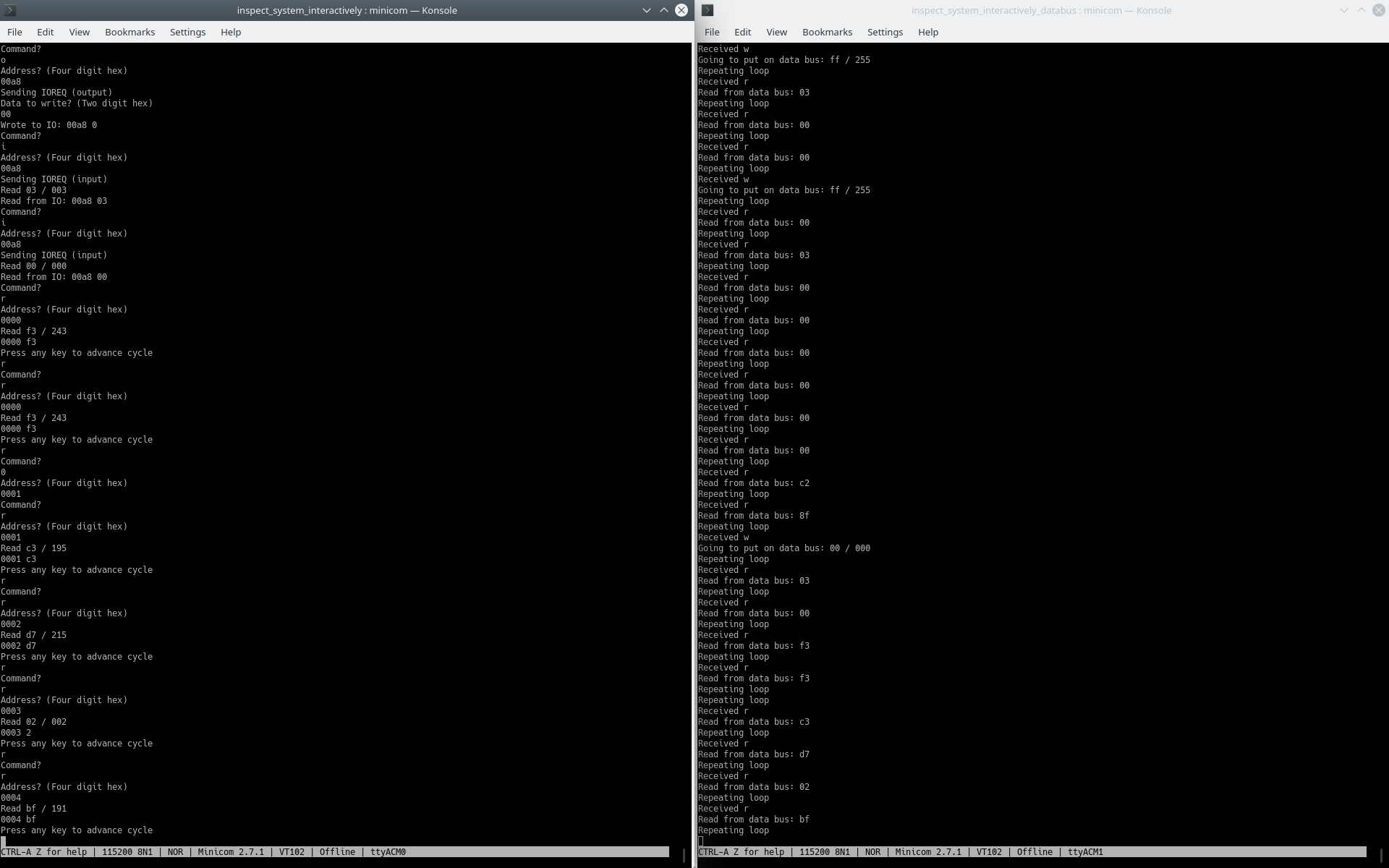
So, suspecting that I had some kind of severe fault, and not having come up with the logic analyzer “idea” yet, and noticing that the CPU was socketed, I decided to take out the CPU and just generate the signals that the CPU would generate myself, using two Raspberry Pi Picos. (Because I needed a lot of pins, not necessarily performance.) One Pico is responsible for the address and control pins, the other for the data pins. As I noticed some time in, Pico 1 should have had the data and control pins, Pico 2 the address pins. Why? Timing matters with the data pins, but for address pins you can be super slow and it’ll be fine. It still worked out in the end.

Pico 1 controls Pico 2 via UART. A host computer (yes, you, Mr. ThinkPad) controls Pico 1 via serial. Then some idiot (yes, me) types in commands into a serial terminal, and Pico 1 does the idiot’s bidding. The following commands are recognized:

  • i, for IOREQ input
  • o, for IOREQ output
  • v, for VRAM manipulation, which I actually couldn’t get to work the way I expected, but it still does something
  • r, for RAM reads
  • w, for RAM writes (and a simple readback to make sure the RAM stores stuff)
  • W, for RAM writes with RAM refresh (and a readback after every refresh). You can specify the amount of writes between refreshes and stuff.
  • s, sync UART (flushes out all characters stuck in the UART read buffer)
  • 0: ask Pico 2 to set data bus to 0
  • u: ask Pico 2 to unset data bus (i.e., to set bus direction from: GPIO_OUT to: GPIO_IN)

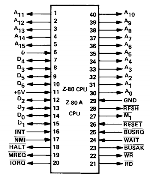
So, how does it work? How does the Z80 work? Let’s have a look at the Z80 pinout:

The A pins are the address pins. The D pins are the data pins. So if you want to write 0 to address 0, all those pins will be 0. In addition, RD will be high, and WR will be low, because we are writing. (Yes, 0 means “active” and 1 means “inactive”.) In addition, we are writing to memory, not to IO space. So IORQ is 1 and MREQ is 0. (Also M1 goes from 1 to 0 too, but I don’t remember the details there.) If we instead want to talk to hardware, we need to know the hardware address and set IORQ to 0 instead of MREQ. On the Z80, only A0 to A7 matter for IO addresses. Well, that’s the gist of it.

With a crude thing like this, we can:

  • Dump the main ROM and check that the contents are correct
  • Check if memory works
  • Check if the sound chip works
  • Check if the video chip works
  • Check if the IO controller works
    • We can turn the tape motor on and off
    • We can map memory
    • Etc.?
  • (Provided the connection from CPU to the above peripherals is working)

I was able to check all of the above. Note that in the highly unlikely event that you decide to run any of this on your MSX machine, note that memory mapping is a bit different from machine to machine. (Which is important, otherwise RAM expansions wouldn’t work, right?)

So here are some examples of commands I’d paste into my terminal:

# Turn off tape motor (which is on by default IIRC?), map memory, maybe some other stuff (I got these by running the MB-H2 in openmsx and checking the earliest 'in's and 'out's in openmsx-debugger, also see below screenshot)
# Execute this before executing anything else!
o00ab82o00aa50o00a800o00a850o00a8a0o00a8f0

# Read first 16 bytes of ROM
r0000rr0001rr0002rr0003rr0004rr0005rr0006rr0007rr0008rr0009rr000arr000brr000crr000drr000err000frr0010r

# Read bits 0, 1, 2, 3, 4, 5, 6, 7, 8, 9, 10, 11, 12, 13, 14, and 15 (counting bits from 0) (if you get the right result here you'll know that your connections are good)
r0001rr0002rr0004rr0008rr0010rr0020rr0040rr0080rr0100rr0200rr0400rr0800rr1000rr2000rr4000rr8000r

# Expected result of above command for MB-H2:
sed -n -e '2p' -e '3p' -e '5p' -e '9p' -e '17p' -e '33p' -e '65p' -e '129p' -e '257p' -e '513p' -e '1025p' -e '2049p' -e '4097p' -e '8193p' -e '16385p' 32k_v2.hex
c3
d7
bf
c3
c3
c3
13
06
ee
2a
e5
32
a4
00
e5
head -n 1 16k_v2.hex
41

# Set background colors:
o00990fo009987 # white background
o00990eo009987 # gray
o00990do009987 # magenta
o00990co009987 # dark green
o00990bo009987 # light yellow
o00990ao009987 # dark yellow
o009909o009987 # light red
o009908o009987 # medium red
o009907o009987 # cyan
o009906o009987 # dark red
o009905o009987 # light blue
o009904o009987 # dark blue
o009903o009987 # light green
o009902o009987 # medium green
o009901o009987 # black

# click sound test:
o00ab0fo00ab0eo00ab0fo00ab0eo00ab0fo00ab0e

# VRAM notes (worked partially, but I think you may need to change the video mode to something else in order to get full VRAM access like this? Never really got it to work as expected. IIRC, the values would stick for a bit, and then go back to 0f or something)
# To read from 0000 to ... (address is auto-incremented, so you only have to set it once):
o009900 # set lower byte of address
o009900 # set upper byte of address (bit 7 and 6 are low to indicate that we want to read)
i0098 # read from 0000
i0098 # read from 0001
i0098 # read from 0002
i0098 # read from 0003
...
# bunched into a single line:
o009900o009900i0098i0098i0098i0098
# To write ff to 0000-... (address is auto-incremented, so you only have to set it once):
o009900 # set lower byte of address
o009940 # set upper byte of address (bit 7 is low and bit 6 is high to indicate that we want to write)
o0098ff # set data register to ff to write to 0000
o0098ff # set data register to ff to write to 0001
o0098ff # set data register to ff to write to 0002
o0098ff # set data register to ff to write to 0003
...
# bunched into a single line:
o009900o009940o0098ffo0098ffo0098ff

What’s a good story without pictures?

openmsx-debugger early in the boot process (looking for RAM)
Serial terminal for Pico 1 (left) and Pico 2 (right) (Pico 2’s output is just debug output, and doesn’t accept commands from this serial connection)
I put a 40-pin socket in the existing 40-pin socket, and directly clipped in breadboard jumper wire. It worked, but wasn’t fun. I still stuck with this setup. Note: maybe half the wires pictured here are actually part of the computer. Yes, this computer has many, many wires inside.
BTW, just one Pico here because I thought it’d be worth something with just a couple bits on the data bus. But yeah, that wasn’t very fun.
Now running with two Raspberry Pi Picos. At first I tried using an automatic level shifter, but that didn’t work. Possibly because the data bus’ idle voltage (when everything is at high impedance) is at around 2V. I think I even saw a datasheet somewhere recommending doing that, maybe the 4164 RAM?
And here’s a tiny minicom script cycling through the background colors (see below)
sleep 5
send o009900o009980\c
send o009903o009981\c
send o009900o009987\c
sleep 1
send o009901o009987\c
sleep 1
send o009902o009987\c
sleep 1
send o009903o009987\c
sleep 1
send o009904o009987\c
sleep 1
send o009905o009987\c
sleep 1
send o009906o009987\c
sleep 1
send o009907o009987\c
sleep 1
send o009908o009987\c
sleep 1
send o009909o009987\c
sleep 1
send o00990ao009987\c
sleep 1
send o00990bo009987\c
sleep 1
send o00990co009987\c
sleep 1
send o00990do009987\c
sleep 1
send o00990eo009987\c
sleep 1
send o00990fo009987\c

The code

Danger: do not submit code to code beauty contests.

The code consists of two separate projects, in CMake terms. One is for Pico 1, the other is for Pico 2. First of all the CMakeLists.txt files are as follows:

Pico 1 (create a directory called e.g. inspect_system_interactively and in there, create a file called CMakeLists.txt with the following contents):

cmake_minimum_required(VERSION 3.12)

# Pull in SDK (must be before project)
include(pico_sdk_import.cmake)

project(pico_examples C CXX ASM)
set(CMAKE_C_STANDARD 11)
set(CMAKE_CXX_STANDARD 17)

if (PICO_SDK_VERSION_STRING VERSION_LESS "1.3.0")
    message(FATAL_ERROR "Raspberry Pi Pico SDK version 1.3.0 (or later) required. Your version is ${PICO_SDK_VERSION_STRING}")
endif()

set(PICO_EXAMPLES_PATH ${PROJECT_SOURCE_DIR})

# Initialize the SDK
pico_sdk_init()

include(example_auto_set_url.cmake)

add_compile_options(-Wall -Wextra
        -Wno-format          # int != int32_t as far as the compiler is concerned because gcc has int32_t as long int
        -Wno-unused-function # we have some for the docs that aren't called
        -Wno-maybe-uninitialized
        -O3
        )

add_executable(inspect_system_interactively
        inspect_system_interactively.c
        )

# pull in common dependencies
target_link_libraries(inspect_system_interactively pico_stdlib)

# enable usb output, disable uart output
pico_enable_stdio_usb(inspect_system_interactively 1)
pico_enable_stdio_uart(inspect_system_interactively 0)

# create map/bin/hex file etc.
pico_add_extra_outputs(inspect_system_interactively)

# add url via pico_set_program_url
example_auto_set_url(inspect_system_interactively)

Pico 2 (my directory name is inspect_system_interactively_databus):

cmake_minimum_required(VERSION 3.12)

# Pull in SDK (must be before project)
include(pico_sdk_import.cmake)

project(pico_examples C CXX ASM)
set(CMAKE_C_STANDARD 11)
set(CMAKE_CXX_STANDARD 17)

if (PICO_SDK_VERSION_STRING VERSION_LESS "1.3.0")
    message(FATAL_ERROR "Raspberry Pi Pico SDK version 1.3.0 (or later) required. Your version is ${PICO_SDK_VERSION_STRING}")
endif()

set(PICO_EXAMPLES_PATH ${PROJECT_SOURCE_DIR})

# Initialize the SDK
pico_sdk_init()

include(example_auto_set_url.cmake)

add_compile_options(-Wall -Wextra
        -Wno-format          # int != int32_t as far as the compiler is concerned because gcc has int32_t as long int
        -Wno-unused-function # we have some for the docs that aren't called
        -Wno-maybe-uninitialized
        -O3
        )

add_executable(inspect_system_interactively_databus
        inspect_system_interactively_databus.c
        )

# pull in common dependencies
target_link_libraries(inspect_system_interactively_databus pico_stdlib)

# enable usb output, disable uart output
pico_enable_stdio_usb(inspect_system_interactively_databus 1)
pico_enable_stdio_uart(inspect_system_interactively_databus 0)

# create map/bin/hex file etc.
pico_add_extra_outputs(inspect_system_interactively_databus)

# add url via pico_set_program_url
example_auto_set_url(inspect_system_interactively_databus)

You can get the referenced pico_sdk_import.cmake and example_auto_set_url.cmake files from the pico-examples repository (https://github.com/raspberrypi/pico-examples.git).

Next, you need to place the C files into the corresponding directories. Then you just need to execute two commands, “cmake .” followed by “make”, in both directories.

inspect_system_interactively/inspect_system_interactively.c:

#include <stdio.h>
#include "pico/stdlib.h"

#define A11          0
#define A12          1
#define A13          2
#define A14          3
#define A15          4

#define A10         28
#define A9          27
#define A8          26
#define A7          22
#define A6          21
#define A5          20
#define A4          19
#define A3          18
#define A2          17
#define A1          15
#define A0          14

#define MREQ        16 /* active-low */
#define M1          13 /* active-low, we should probably set this and un-set when we're done reading */
#define RFSH        12 /* active-low and we won't be refreshing at all; tie to +5; could also feed inverted MREQ_RD if things don't work otherwise <-- chose to do this */
#define RD           5 /* active-low */
#define WR           6 /* active-low */
#define IOREQ        7 /* active-low */
/* #define HALT        active-low but shouldn't be a problem to keep this floating */

#define UART1_TX     8
#define UART1_RX     9
// #define BAUD    345600
#define BAUD    460800

#define READ_BACK_SIGNAL 10
#define READ_BACK_SIGNAL_ACK 11

#define HIGH         1
#define LOW          0

#ifndef PICO_DEFAULT_LED_PIN
#error blink requires a board with a regular LED
#endif

#define STATUS_LED PICO_DEFAULT_LED_PIN
// #define STATUS_LED 15

#define BUS_SIZE 16

// #define SLOW_PERF 1

const unsigned int a_bus[BUS_SIZE] = {
  A0, A1, A2, A3, A4, A5, A6, A7, A8, A9, A10, A11, A12, A13, A14, A15
};

#define println printf
// #define printf(...) ;

inline void nop(void) {
    __asm__ __volatile__("nop\t\n");
}

void setup() {
    gpio_init(A0);
    gpio_init(A1);
    gpio_init(A2);
    gpio_init(A3);
    gpio_init(A4);
    gpio_init(A5);
    gpio_init(A6);
    gpio_init(A7);
    gpio_init(A8);
    gpio_init(A9);
    gpio_init(A10);
    gpio_init(A11);
    gpio_init(A12);
    gpio_init(A13);
    gpio_init(A14);
    gpio_init(A15);
    gpio_init(MREQ);
    gpio_init(IOREQ);
    gpio_init(RD);
    gpio_init(WR);
    gpio_init(M1);
    gpio_init(RFSH);
    gpio_init(STATUS_LED);
    gpio_init(READ_BACK_SIGNAL);
    gpio_init(READ_BACK_SIGNAL_ACK);

    /* Not 100% sure if the default is LOW for all pins so let's set this early and once more after gpio_set_dir to be 100% sure */
    gpio_put(A0, LOW);
    gpio_put(A1, LOW);
    gpio_put(A2, LOW);
    gpio_put(A3, LOW);
    gpio_put(A4, LOW);
    gpio_put(A5, LOW);
    gpio_put(A6, LOW);
    gpio_put(A7, LOW);
    gpio_put(A8, LOW);
    gpio_put(A9, LOW);
    gpio_put(A10, LOW);
    gpio_put(A11, LOW);
    gpio_put(A12, LOW);
    gpio_put(A13, LOW);
    gpio_put(A14, LOW);
    gpio_put(A15, LOW);
    gpio_put(MREQ, HIGH);
    gpio_put(IOREQ, HIGH);
    gpio_put(RD, HIGH);
    gpio_put(WR, HIGH);
    gpio_put(M1, HIGH);
    gpio_put(RFSH, HIGH);
    gpio_put(READ_BACK_SIGNAL, LOW);

    gpio_set_dir(A0, GPIO_OUT);
    gpio_set_dir(A1, GPIO_OUT);
    gpio_set_dir(A2, GPIO_OUT);
    gpio_set_dir(A3, GPIO_OUT);
    gpio_set_dir(A4, GPIO_OUT);
    gpio_set_dir(A5, GPIO_OUT);
    gpio_set_dir(A6, GPIO_OUT);
    gpio_set_dir(A7, GPIO_OUT);
    gpio_set_dir(A8, GPIO_OUT);
    gpio_set_dir(A9, GPIO_OUT);
    gpio_set_dir(A10, GPIO_OUT);
    gpio_set_dir(A11, GPIO_OUT);
    gpio_set_dir(A12, GPIO_OUT);
    gpio_set_dir(A13, GPIO_OUT);
    gpio_set_dir(A14, GPIO_OUT);
    gpio_set_dir(A15, GPIO_OUT);
    gpio_set_dir(MREQ, GPIO_OUT);
    gpio_set_dir(IOREQ, GPIO_OUT);
    gpio_set_dir(RD, GPIO_OUT);
    gpio_set_dir(WR, GPIO_OUT);
    gpio_set_dir(M1, GPIO_OUT);
    gpio_set_dir(RFSH, GPIO_OUT);
    gpio_set_dir(STATUS_LED, GPIO_OUT);
    gpio_set_dir(READ_BACK_SIGNAL, GPIO_OUT);
    gpio_set_dir(READ_BACK_SIGNAL_ACK, GPIO_IN);

    gpio_put(A0, LOW);
    gpio_put(A1, LOW);
    gpio_put(A2, LOW);
    gpio_put(A3, LOW);
    gpio_put(A4, LOW);
    gpio_put(A5, LOW);
    gpio_put(A6, LOW);
    gpio_put(A7, LOW);
    gpio_put(A8, LOW);
    gpio_put(A9, LOW);
    gpio_put(A10, LOW);
    gpio_put(A11, LOW);
    gpio_put(A12, LOW);
    gpio_put(A13, LOW);
    gpio_put(A14, LOW);
    gpio_put(A15, LOW);
    gpio_put(MREQ, HIGH);
    gpio_put(IOREQ, HIGH);
    gpio_put(RD, HIGH);
    gpio_put(WR, HIGH);
    gpio_put(M1, HIGH);
    gpio_put(RFSH, HIGH);
    gpio_put(READ_BACK_SIGNAL, LOW);

    gpio_set_function(UART1_TX, GPIO_FUNC_UART);
    gpio_set_function(UART1_RX, GPIO_FUNC_UART);
}

void set_bus(uint16_t address) {
    int i;
    /* Write lowest bit into lowest address line first, then next-lowest bit, etc. */
    for (i = 0; i < BUS_SIZE; i++) {
        gpio_put(a_bus[i], address & 1);
        address >>= 1;
    }
}

bool uart_read_data_bus(bool data_bus_is_already_set, uint32_t *recv_data) {
    char buf[3] = { 0 };

    if (!data_bus_is_already_set) {
#ifdef SLOW_PERF 
        gpio_put(STATUS_LED, HIGH);
#endif
        uart_putc_raw(uart1, 'r');
    }
    uart_read_blocking(uart1, (uint8_t*)buf, sizeof(buf)-1);
    if (!data_bus_is_already_set) {
#ifdef SLOW_PERF
        while (uart_is_readable(uart1)) {
            printf("Read one more unexpected byte: %02x\n", uart_getc(uart1));
        }
        gpio_put(STATUS_LED, LOW);
#endif
    }
//     printf("Read something: %x %x\n", buf[0], buf[1]);
    if (!sscanf((char*)buf, "%02x", recv_data)) {
//         printf("Communication error?\n");
        return false;
    }
#ifdef SLOW_PERF
    else {
        printf("Read %02x / %03d\n", *recv_data, *recv_data);
    }
#endif
    return true;
}

void uart_write_data_bus(bool io, uint8_t send_data) {
    char buf[3] = { 0 };
    sprintf(buf, "%02x", send_data);
    gpio_put(STATUS_LED, HIGH);
    uart_putc_raw(uart1, io ? 'o' : 'w');
    uart_puts(uart1, buf);
    gpio_put(STATUS_LED, LOW);
}

uint32_t get_address_from_stdin() {
    char stdin_buf[5] = { 0 };
    uint32_t address = 0;
    stdin_buf[0] = getchar();
    stdin_buf[1] = getchar();
    stdin_buf[2] = getchar();
    stdin_buf[3] = getchar();
    sscanf(stdin_buf, "%04x", &address);
    printf("\n");
    return address;
}

uint32_t get_data_from_stdin() {
    char stdin_buf[5] = { 0 };
    uint32_t data = 0;
    printf("Data to write? (Two digit hex)\n");
    stdin_buf[0] = getchar();
    stdin_buf[1] = getchar();
    stdin_buf[2] = 0;
    sscanf(stdin_buf, "%02x", &data);
    printf("\n");
    return data;
}

void refresh_dram() {
    uint16_t row_address, temp;
    int i;
    set_bus(0);
    for (row_address = 0; row_address < 256; row_address++) {
        temp = row_address;
        for (i = 0; i < 8; i++) {
            gpio_put(a_bus[i], temp & 1);
            temp >>= 1;
        }
        gpio_put(RFSH, LOW);
        gpio_put(MREQ, LOW);
        // Need to wait at least 150 ns, 20 * (1000/133) ~= 150. In reality this probably works out to be more than 150 ns
        nop();
        nop();
        nop();
        nop();
        nop();

        nop();
        nop();
        nop();
        nop();
        nop();

        nop();
        nop();
        nop();
        nop();
        nop();

        nop();
        nop();
        nop();
        nop();
        nop();
        gpio_put(MREQ, HIGH);
        gpio_put(RFSH, HIGH);
        // Need to delay at least 100 ns, which we'll probably already be doing by setting up the bus with the next address, but let's add some NOPs anyway and then measure
        nop();
        nop();
        nop();
        nop();
        nop();

        nop();
        nop();
        nop();
        nop();
        nop();
    }
}

void write_vram_address(bool is_write, uint8_t high_byte, uint8_t low_byte) {
    if (is_write) {
        high_byte |= 0x40;
    }
    set_bus(0x99);

    uart_write_data_bus(true, low_byte);
    uart_getc(uart1); // Slave takes time to actually set data bus, let's wait for an 'f' char to indicate this op is done
    gpio_put(IOREQ, LOW);
    gpio_put(WR, LOW);
    sleep_ms(1);
    gpio_put(WR, HIGH);
    gpio_put(IOREQ, HIGH);

    uart_write_data_bus(true, high_byte);
    uart_getc(uart1); // Slave takes time to actually set data bus, let's wait for an 'f' char to indicate this op is done
    gpio_put(IOREQ, LOW);
    gpio_put(WR, LOW);
    sleep_ms(1);
    gpio_put(WR, HIGH);
    gpio_put(IOREQ, HIGH);
}

int main() {
//     char stdin_buf[5] = { 0 };
    uint32_t address = 0, end_address = 0;
    int i = 0;
    uint32_t j = 0, k = 0;
    char command = 0;
    uint32_t data = 0;
    uint32_t read_val = 0;
    char data_bus_ready = 0;
    uint32_t n_refresh_cycles = 0, n_writes_until_refresh = 0, only_write_first_time = 0;
    uint8_t high_byte = 0, low_byte = 0;
    int n_vram_writes = 0;
//     bool status = 0;

    stdio_init_all();
    setup();
    uart_init(uart1, BAUD);
    
    /* play with the LED so we can see that the program is about to start */
    for (i = 0; i < 5; i++) {
        gpio_put(STATUS_LED, HIGH);
        sleep_ms(500);
        gpio_put(STATUS_LED, LOW);
        sleep_ms(500);
    }
    sleep_ms(4000);

    printf("Ready\n");

    while (true) {
        read_val = 0;
    
        printf("Command?\n");
        command = getchar();
        printf("\nAddress? (Four digit hex)\n");
        address = get_address_from_stdin();
        switch (command) {
            case 'i':
                printf("Sending IOREQ (input)\n");
                set_bus(address);
                gpio_put(IOREQ, LOW);
                gpio_put(RD, LOW);
                if (!uart_read_data_bus(false, &read_val)) {
                    printf("RECV ERR\n");
                }
                gpio_put(RD, HIGH);
                gpio_put(IOREQ, HIGH);
                printf("Read from IO: %04x %02x\n", address, read_val);
                break;
            case 'o':
                printf("Sending IOREQ (output)\n");
                data = get_data_from_stdin();
                set_bus(address);
                uart_write_data_bus(true, data);
                uart_getc(uart1); // Slave takes time to actually set data bus, let's wait for an 'f' char to indicate this op is done
                gpio_put(IOREQ, LOW);
                gpio_put(WR, LOW);
                sleep_ms(1);
                gpio_put(WR, HIGH);
                gpio_put(IOREQ, HIGH);
                printf("Wrote to IO: %04x %1x\n", address, data);
                break;
            case 'v':
                low_byte = address & 0xff;
                high_byte = (address & 0x3f00) >> 8;
                printf("Number of writes? (Four digit hex)\n");
                n_vram_writes = get_address_from_stdin();
                data = get_data_from_stdin();

                write_vram_address(true, high_byte, low_byte);
                set_bus(0x98);
                uart_write_data_bus(true, data);
                uart_getc(uart1); // Slave takes time to actually set data bus, let's wait for an 'f' char to indicate this op is done
                for (i = 0; i < n_vram_writes; i++) {
                    gpio_put(IOREQ, LOW);
                    gpio_put(WR, LOW);
                    sleep_ms(1); // use VRAM_IO_DELAY macro?
                    gpio_put(WR, HIGH);
                    gpio_put(IOREQ, HIGH);
                }

                write_vram_address(false, high_byte, low_byte);
                set_bus(0x98);
                for (i = 0; i < n_vram_writes; i++) {
                    gpio_put(IOREQ, LOW);
                    gpio_put(RD, LOW);
                    uart_read_data_bus(false, &read_val);
                    gpio_put(RD, HIGH);
                    gpio_put(IOREQ, HIGH);
                    if (read_val != data) {
                        printf("Mismatch at VRAM address %04x: read %02x expected %02x\n", address+i, read_val, data);
                    }
                }
                break;
            case 'r':
                set_bus(address);
                gpio_put(MREQ, LOW);
                gpio_put(RD, LOW);
                gpio_put(M1, LOW);
//                 sleep_ms(1);
                if (!uart_read_data_bus(false, &read_val)) {
                    printf("RECV ERR\n");
//                     return 1;
                }

                printf("%04x %1x\n", address, read_val);
                printf("Press any key to advance cycle\n");
                getchar();
                printf("\n");
                sleep_ms(1);
                gpio_put(M1, HIGH);
                gpio_put(RD, HIGH);
                gpio_put(MREQ, HIGH);
                gpio_put(RFSH, LOW);
                sleep_ms(1);
                gpio_put(RFSH, HIGH);
                break;
            case 'w':
            case 'W':
                printf("End address? (Four digit hex, 0000 for 1-byte write)\n");
                end_address = get_address_from_stdin();
                if (end_address < address) {
                    end_address = address;
                }
                data = get_data_from_stdin();
                if (command == 'W') {
                    printf("Number of refresh cycles? (Four digit hex)\n");
                    n_refresh_cycles = get_data_from_stdin(); // use get_address_from_stdin to actually get four bytes
                    printf("Refresh every n writes? (Four digit hex)\n");
                    n_writes_until_refresh = get_data_from_stdin();
                    printf("Only write first time? (0000: no, 0001: yes)\n");
                    only_write_first_time = get_data_from_stdin();
                } else {
                    n_refresh_cycles = 1;
                }
                for (k = 0; k < n_refresh_cycles; k++) {
                    for (j = address; j <= end_address; j++) {
                        set_bus(j);
                        if (k == 0 || !only_write_first_time) {
                            uart_write_data_bus(false, data);
                            data_bus_ready = uart_getc(uart1);
                            if (data_bus_ready == 'f') { // Slave takes time to actually set data bus, let's wait for an 'f' char to indicate this op is done
                                printf("Got 'f'\n");
                            } else {
                                printf("Warning: got '%c' (%02x) instead of 'f'\n", data_bus_ready, data_bus_ready);
                            }
                            gpio_put(WR, LOW);
                            gpio_put(MREQ, LOW);
#define SLEEP_US_DURING_WRITE 3 // was 1
                            sleep_us(SLEEP_US_DURING_WRITE); // should be ~219 ns without this. that's okay generally speaking.
                            gpio_put(WR, HIGH);
                            gpio_put(MREQ, HIGH);
                        }

                        // S command has to take longer than RAM cycle time. should be okay.
                        uart_putc_raw(uart1, 'S'); // force data bus to gpio_in, and stand by for read
                        data_bus_ready = uart_getc(uart1); // gpio_in is done, slave is standing by

                        gpio_put(RD, LOW);
                        gpio_put(MREQ, LOW);
                        // perhaps our timing is just a bit tight? let's add a small delay
                        // much better but still not that great, let's do 1 us
#define SLEEP_US_DURING_READ_BACK 1 // was 1
                        sleep_us(SLEEP_US_DURING_READ_BACK);
                        gpio_put(READ_BACK_SIGNAL, HIGH);
                        while (!gpio_get(READ_BACK_SIGNAL_ACK)) {}

                        gpio_put(READ_BACK_SIGNAL, LOW);
                        gpio_put(RD, HIGH);
                        gpio_put(MREQ, HIGH);

                        if (!uart_read_data_bus(true, &read_val)) {
                            printf("RECV ERR\n");
                        }
                        printf("Wrote %04x and read back: %04x %1x\n", data, j, read_val);
                        if (command == 'W') {
                            if ((j-address) % n_writes_until_refresh == 0) {
                                refresh_dram();
                            }
                        }
                    }
                }
                break;
            case 's': // sync uart
                while (uart_is_readable(uart1)) {
                    printf("%c", uart_getc(uart1));
                }
                printf("\n");
                break;
            case '0':
                uart_putc_raw(uart1, '0');
                break;
            case 'u':
                uart_putc_raw(uart1, 'u');
                break;
            default:
                printf("Unknown command: \"%c\"\n", command);
        }
    }

    while (true) {
        gpio_put(STATUS_LED, HIGH);
        sleep_ms(1000);
        gpio_put(STATUS_LED, LOW);
        sleep_ms(1000);
    }
}

inspect_system_interactively_databus/inspect_system_interactively_databus.c:

#include <stdio.h>
#include "pico/stdlib.h"

#define D7           7
#define D6           6
#define D5           5
#define D4           4
#define D3           3
#define D2           2
#define D1           1
#define D0           0

#define UART1_TX     8
#define UART1_RX     9
// #define BAUD    345600
#define BAUD    460800

#define READ_BACK_SIGNAL 28
#define READ_BACK_SIGNAL_ACK 27

#define HIGH         1
#define LOW          0

#ifndef PICO_DEFAULT_LED_PIN
#error blink requires a board with a regular LED
#endif

#define STATUS_LED PICO_DEFAULT_LED_PIN
// #define STATUS_LED 15

#define println printf
// #define println(...) ;

inline void nop(void) {
    __asm__ __volatile__("nop\t\n");
}

void setup() {
    gpio_init(D0);
    gpio_init(D1);
    gpio_init(D2);
    gpio_init(D3);
    gpio_init(D4);
    gpio_init(D5);
    gpio_init(D6);
    gpio_init(D7);

    gpio_init(STATUS_LED);
    gpio_init(READ_BACK_SIGNAL);
    gpio_init(READ_BACK_SIGNAL_ACK);
    
    gpio_set_dir(D0, GPIO_IN);
    gpio_set_dir(D1, GPIO_IN);
    gpio_set_dir(D2, GPIO_IN);
    gpio_set_dir(D3, GPIO_IN);
    gpio_set_dir(D4, GPIO_IN);
    gpio_set_dir(D5, GPIO_IN);
    gpio_set_dir(D6, GPIO_IN);
    gpio_set_dir(D7, GPIO_IN);
    gpio_set_dir(STATUS_LED, GPIO_OUT);
    gpio_set_dir(READ_BACK_SIGNAL, GPIO_IN);
    gpio_set_dir(READ_BACK_SIGNAL_ACK, GPIO_OUT);

    gpio_put(READ_BACK_SIGNAL_ACK, LOW);

    gpio_set_function(UART1_TX, GPIO_FUNC_UART);
    gpio_set_function(UART1_RX, GPIO_FUNC_UART);
}

#define DATA_BUS_SIZE 8

const unsigned int d_bus[DATA_BUS_SIZE] = {
  D0, D1, D2, D3, D4, D5, D6, D7
};

void set_data_bus_dir(uint32_t dir) {
    gpio_set_dir(D0, dir);
    gpio_set_dir(D1, dir);
    gpio_set_dir(D2, dir);
    gpio_set_dir(D3, dir);
    gpio_set_dir(D4, dir);
    gpio_set_dir(D5, dir);
    gpio_set_dir(D6, dir);
    gpio_set_dir(D7, dir);
}

void set_data_bus(uint8_t data) {
    int i;
    set_data_bus_dir(GPIO_OUT);
    /* Write lowest bit into lowest address line first, then next-lowest bit, etc. */
    for (i = 0; i < DATA_BUS_SIZE; i++) {
        gpio_put(d_bus[i], data & 1);
        data >>= 1;
    }
}

void get_data_bus(uint8_t *data) {
    int i;
    *data = 0;
    /* Write lowest bit into lowest address line first, then next-lowest bit, etc. */
    for (i = 0; i < DATA_BUS_SIZE; i++) {
        *data |= (gpio_get(d_bus[i]) << i);
    }
}

int main() {
    uint32_t recv_data = 0;
    uint8_t recv_data8 = 0;
    char c;
    uint8_t buf[3] = { 0 };
    setup();
    stdio_init_all();
    uart_init(uart1, BAUD); // 115200);

    while(true) {
        printf("Repeating loop\n");
        gpio_put(STATUS_LED, HIGH);
        c = uart_getc(uart1);
        gpio_put(STATUS_LED, LOW);
        switch (c) {
            case 'w':
            case 'o':
                printf("Received w\n");
                uart_read_blocking(uart1, buf, sizeof(buf)-1);
                if (!sscanf((char*)buf, "%02x", &recv_data)) {
                    printf("Communication error?\n");
                } else {
                    printf("Going to put on data bus: %02x / %03d\n", recv_data, recv_data);
                }
                set_data_bus(recv_data);
                uart_putc_raw(uart1, 'f'); // indicate that we're done setting the bus
                break;
            case 'u': // unset data bus
            case 'S': // unset data bus and then stand by for read
                set_data_bus_dir(GPIO_IN);
                uart_putc_raw(uart1, 'f');
                if (c == 'S') { // stand by for read
                    // UART communication turned out to be a bit slow so we sacrificed one more pin just to get a signal when to read the bus
                    while (!gpio_get(READ_BACK_SIGNAL)) {} // wait for read signal
                    nop();
                    nop();
                    nop();
                    nop();
                    nop();
                    nop();
                    nop();
                    nop();
                    nop();
                    nop();
                    get_data_bus(&recv_data8);
                    gpio_put(READ_BACK_SIGNAL_ACK, HIGH);
                    recv_data = recv_data8;
                    sprintf((char*)buf, "%02x", recv_data);
                    printf("Read from data bus: %s\n", (char*)buf);
                    uart_puts(uart1, (char*)buf);
                    gpio_put(READ_BACK_SIGNAL_ACK, LOW);
                }
                break;
            case 'r':
                printf("Received r\n");
                set_data_bus_dir(GPIO_IN);
                get_data_bus(&recv_data8);
                recv_data = recv_data8;
                sprintf((char*)buf, "%02x", recv_data);
                printf("Read from data bus: %s\n", (char*)buf);
                uart_puts(uart1, (char*)buf);
                break;
            case '0': /* set data bus to 0 */
                set_data_bus(0);
                break;
            default:
                printf("Unexpected command char\n");
        }
    }
}

I’ll consider putting this on my Github account at some point. Code license is public domain.