(I do not recommend watching this demo on a smartphone. It’s quite flashy and exacerbated my headache. Also, the WebMSX code will ask you to go fullscreen, but I don’t think you can start the demo without going fullscreen and then back again.)
In part 1, we constructed a 48 KB ROM to play a tune called “Popsa 2”. We didn’t apply any real compression algorithms but implemented a set of scripts to find repeated sections in a binary file and added an instruction to the .psg file format to “call” repeated sections. Using real compression algorithms we could achieve much better compression, and each tune would just occupy a couple KBs. Using our method, we _just_ manage to fit the tune into a single cartridge. Popsa 2 fit into 48 KB, and the tune we’re going to do today is going to require a 64 KB ROM. If the previous track didn’t quite do it for you, I think it might be worth giving this one a chance. It’s a very complex piece of wonder-inducing music in my opinion. (Press the power button and in the menu that pops up, choose “Power” to boot the ROM.)
64 KB ROMs still require a header at 0x4000 or 0x8000. This means that we need to add a header and some entrypoint code to set up the slots right in the middle of our data. That’s inconvenient, but I didn’t feel like changing the structure of the program, so I just added one check each at the beginning and end of the main loop to see if the HL register has gone above a certain value. If yes: before the main loop, it adds an offset; after the main loop, it subtracts the same offset again. This way, we don’t have to do anything too complex when jumping to a previous section of the track.
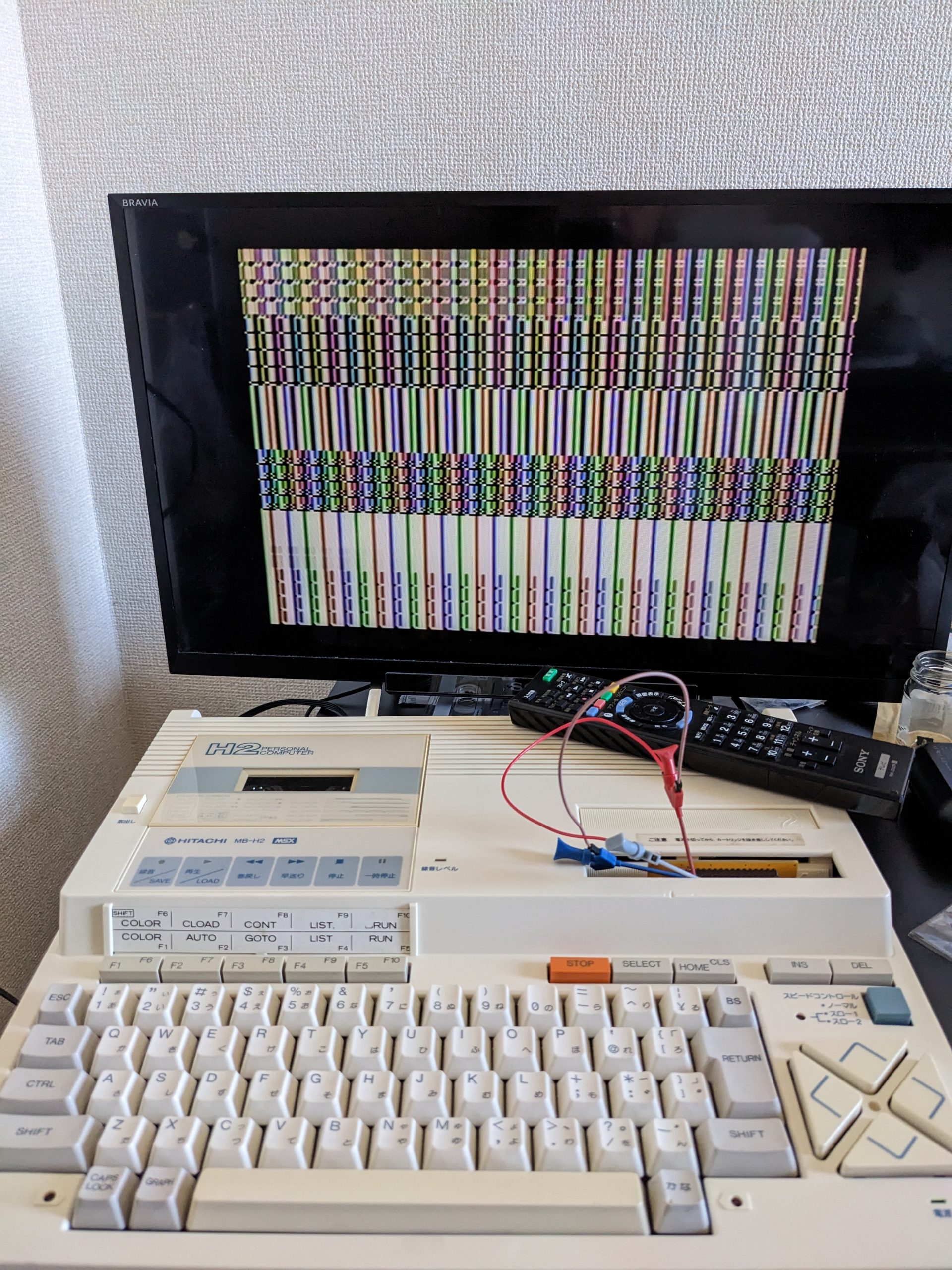
In part 1, I mentioned a problem in WebMSX that prevented the 48 KB ROM from working. 64 KB ROMs are not affected by this problem. The WebMSX player at the top of this article page plays the ROM linked to above. The ROM also works on real hardware (the Hitachi MB-H2 MSX1 I repaired a while ago).
Aside: disabling WebMSX’ auto-scroll
In the unlikely event that you have read this blog’s front page sometime in the last few months, you might have noticed that it scrolled automatically to this WebMSX player, even though this post is now very much not the newest post on this blog! I only noticed this a short while ago and decided to fix it, because it’s quite annoying. The below code snippets are taken from the WebMSX commit with the tag “v6.0.4”. Older or newer versions may look different.
All you need to do is remove the “this.focus()” line in the powerOn function in CanvasDisplay.js:
    this.powerOn = function() {
        this.setDefaults();
        updateLogo();
        document.documentElement.classList.add("wmsx-started");
        setPageVisibilityHandling();
        this.focus(); // <-- this is the line you need to remove or comment out
        if (WMSXFullScreenSetup.shouldStartInFullScreen()) {
            setFullscreenState(true);
            if (FULLSCREEN_MODE !== 2 & isMobileDevice) setEnterFullscreenByAPIOnFirstTouch();       // Not if mode = 2 (Windowed)
        }
    };
If you prefer to just edit the minified version, search for the call to setPageVisibilityHandling() and then edit out the “this.focus(),” bit.
This article is somewhat technical. If you just want to listen to a chip tune on WebMSX, maybe go for part 2 instead.
In previous articles I explored the YM2151 and the VGM file format. In this article, we’ll go back a generation and listen to some tunes written for the DSG (doorbell sound generator) PSG (programmable sound generator, i.e., the General Instruments AY-3-8910, or compatibly, Yamaha’s YM2149). PSG files (and particularly ASC files) are mainly used for ZX Spectrum chip tunes (I think), but the MSX has the same sound chip so why not play some chip tunes on the MSX?
Well, before we spend time working on something just slightly above PC beeper music… are there even any decent PSG tunes? Well, I’ve found at least one that like, “Popsa 2”, as is included in the below mix (scroll down a bit) on YouTube for example, and some of the commenters on this video seem to like “Illusion”.
Unfortunately, it doesn’t work in WebMSX (after 20 seconds or so). But it works in all three (NTSC) openMSX machines I bothered to test with, and it also works on my real MSX1 (Hitachi MB-H2). To get it to run in WebMSX, you have to “Set ROM format” -> “KonamiSCC”, but even then it’ll crash after a few minutes (vs. 20 seconds for e.g. ASCII8). For some reason it doesn’t let me choose “Normal”. I’m quite sure it would work with that setting if it were available. :p I’ll look into the matter at some point, probably. Looks like WebMSX will require a patch to work. Patch is submitted and will probably make it into the next version.
This machine produces NTSC color artifacts like there is no tomorrow.
Caution: writing to certain PSG registers is unsafe on certain MSX machines. I don’t think my code writes to these registers, but I didn’t make 100% sure. (However, openMSX gives you a warning when it notices unsafe writes, and I didn’t get a warning.)
“Popsa 2” was made in a program called ASC Sound Master. The “.asc” file can be downloaded here: https://zxart.ee/eng/authors/d/dreamer/popsa-2/. These .asc files are pretty small. They can be converted to PSG using ZXTune (https://bitbucket.org/zxtune/zxtune/) (and from PSG they can easily be converted to e.g. VGM, see bottom of this post), but the resulting files are too large to fit on a regular MSX1 cartridge.
ZXTune compilation and conversion:
git clone https://bitbucket.org/zxtune/zxtune.git
cd zxtune
make platform=linux system.zlib=1 -C apps/zxtune123/ -j4

bin/linux/release/zxtune123 --convert mode=psg,filename=foo.psg -- Dreamer\ -\ POPSA-2\ \(1994\).asc
The original .asc file is 3720 bytes. The resulting .psg is 129028 bytes. If you convert that to VGM, the resulting size is 187342 bytes.
The PSG file format
The PSG file format is very similar in concept to the VGM file format, except that only one chip is supported, the PSG. It seems it’s primarily used for ZX Spectrum chip tunes. As only one chip is supported, you don’t need the “command byte” that indicates what chip is to be written to. So you only have pairs of “register address” and “register value to write”.
There’s also a header in the first 16 bytes. The first three bytes are “PSG”, dunno about the rest.
The PSG only has 16 (IIRC) registers, and some of those aren’t even relevant for sound. In other words, the registers 0x10 to 0xff don’t exist and the designers of this file format used that opportunity to fit in a “wait” command at 0xff (one raster scan, so 1/50s or 1/60s depending on whether the system is PAL or NTSC). There’s also a command that waits multiple raster intervals, 0xfe, and a command that ends the tune, 0xfd. Ignoring the header, here are the first few bytes of the Popsa 2 PSG file:
All this means: wait 1 raster interval, then write to registers 00 through 0a with values 41, 05, 0b, 01, …, respectively, wait 1 raster interval, write to registers 02, 03, 07, 09, 0a, with values e0, 00, 38, 0d, 0c, respectively, wait 1 raster interval. (As you can see the 0xff command doesn’t take any parameters.)
Now that we know mostly how this file format works, it’s time to think about how to fit roughly 126 KB of data into my 48 KB cartridge. We could easily use an off-the-shelf compression library, but where’s the fun in that? That’s like… modern programming, ew.
We’ll invent another command for PSG, 0xfc, which takes a two-byte parameter that tells it to jump back somewhere (for a while, and then returns to its original location). We also need to write a program that identifies repetitive sections in the music (of which there are plenty). The former is pretty easy, so let’s talk about the latter program first.
Compute MD5 sums of a 100-byte window for every byte in the file. So we end up with 129028-100=128928 MD5 sums. Easy and fast on modern hardware. See code snippet below.
Check if we even have repeated chunks, e.g. by executing: md5sum chunks/* | awk ‘{print $1}’ | sort -n | uniq -c
We may want to check a couple other window sizes to see if we can get better results. A lower window size means we’ll find more repetition, but we need 3 bytes to encode a jump in our PSG file.
Re-assemble PSG file using a quick-and-dirty and probably somewhat buggy script. (See below.)
The resulting data length is 42158 bytes for the Popsa 2 song.
For task (1) we first convert the PSG file into hex, and later into tokens:
xxd -p Dreamer\ -\ POPSA-2\ \(1994\).psg | sed -r -e 's/(..)/\1 /g' | tr -d '\n' > Dreamer\ -\ POPSA-2\ \(1994\).psg.hex
# Then remove 16-byte header using a standard text editor
Then divide the tokens into chunks using the below script, divide_tokens_into_chunks.sh:
#!/bin/bash

N=100 # sliding window length
mkdir -p chunks_N$N
line_count=$(cat tokens | wc -l)
for ((i=0; i<$((line_count-N)); i++)); do
    tail -n +$i tokens | head -n $N > chunks_N$N/chunk_$i
done
rm chunks_N$N/chunk_0 # same as chunk_1
You know, looking back at this code for the first time in a while, I see there’s a nice off-by-1 error and a nice rm command to fix half of the problem. But the great thing about this being a hobby is that I don’t need to care. :)
Next, we have a Perl script that creates our PSG file. It needs some help though, so we do this first:
(We can’t do md5sum chunks_N100/* because that expands to a tad too many arguments in our case. xargs automatically cuts down the number of arguments to a more reasonable value.) This is the main program. Usage: ./compress_aggressive_but_convert_to_psg.pl < chunks_N100_md5sums > foo.psg
#!/usr/bin/perl

# dependencies:
# chunks_N$N/ (directory)
# chunks_N$10_md5sums (file) # example generation: find chunks_N10/ | xargs md5sum > chunks_N10_md5sums

use strict;
use warnings;
use feature "switch";

my $N = 100;

my $md5s = {};
my @chunks;

my $md5;
my $file;

my $debug_logged = 0;
my $lines = [];
my $current_output_byte_number = 0;
for (my $chunk_number = 0; <>; $chunk_number++) {
    /([a-z0-9]+)\s+([a-zA-Z0-9_\/]+)/;
    $md5 = $1;
    $file = $2;
    if (exists $md5s->{$md5}) {
        # can't call chunks that already contain a call because that call would take us beyond the N token window that we can see from where we are
        # that means it's likely we'd generate wrong code
        # so we'll just move on and maybe we'll find a nicer block

        my $target_chunk_number = $md5s->{$md5}->{chunk_number};
        my $concatted_chunks = join('', @chunks[max(0, $target_chunk_number-$N)..min($#chunks, $target_chunk_number+$N)]);
        if (($concatted_chunks =~ /; call/) or # NOTE "call wait_for_raster" is allowed
            ($chunk_number - $target_chunk_number < $N)) {
            # 1) can't convert due to existing call; nothing to be done here, or
            # 2) we can't call something right behind us
            # DANGER let's head back to the non-exists path
            goto NON_EXIST_PATH;
        } else {
            if (!$md5s->{$md5}->{converted_to_call}) {
                convert_to_callable_sub($target_chunk_number);
                $md5s->{$md5}->{converted_to_call} = 1;
            }
            my $output_byte_number_high = int($md5s->{$md5}->{output_byte_number} / 256);
            my $output_byte_number_low = $md5s->{$md5}->{output_byte_number} % 256;
            $chunks[$chunk_number] = sprintf("fc %02x %02x ; call " . $md5s->{$md5}->{output_byte_number} . " ($md5)\n", $output_byte_number_high, $output_byte_number_low);
            $current_output_byte_number += 3;

            # skip next N-1 rows
            for (0..$N-1) {
                my $foo = <>;
                $chunk_number++;
                $chunks[$chunk_number] = "";
            }
        }
    } else {
        $md5s->{$md5} = {};
        $md5s->{$md5}->{chunk_number} = $chunk_number;
        $md5s->{$md5}->{converted_to_call} = 0;
NON_EXIST_PATH:
        open my $fh, '<', $file or die "Can't open \"$file\": $!";
        my $token = <$fh>;
        close $fh;
        my $asm = convert_to_asm($token);
        $md5s->{$md5}->{output_byte_number} = $current_output_byte_number;
        $current_output_byte_number += (scalar(split(" ", $asm)));
        $chunks[$chunk_number] = $asm;
    }
}

print foreach @chunks;

print "infloop:
    jr infloop\n";

# no changes needed
sub convert_to_callable_sub($) {
    my $block_number = shift;
}

# don't actually do anything here
sub convert_to_asm($) {
    my $string = shift;
    return "$string";
}

sub min($$) {
    my ($a, $b) = @_;
    return $a if ($a < $b);
    return $b;
}
sub max($$) {
    my ($a, $b) = @_;
    return $a if ($a > $b);
    return $b;
}
The output of this program is in hex. Now we just need some assembly code to read the data and put it into the PSG registers. Here’s the core part:
ld hl,psg_begin
main_loop:
    ld a,(hl)
    cp 0xff
    jr z,wait
    cp 0xfe
    jr z,wait_n_times
    cp 0xfd
    jr z,end
    cp 0xfc
    jr z,jump
    jr register_write
inc_loop:
    inc hl
    jr loop

wait:
    call wait_for_raster
    jr inc_loop

register_write:
    ld a,(hl)
    out (0xa0),a
    inc hl
    ld a,(hl)
    out (0xa1),a
    jr inc_loop

wait_for_raster:
    in a,(0x99)
    and 128
    cp 128
    jr nz,wait_for_raster
    ret

psg_begin:
    include "foo.psg"
ds 010000h-$ ; fill rest with 0s
Understanding the above should help understanding the full implementation. (The above doesn’t include the code for the 0xfe, 0xfd, and 0xfc commands.) Note that we can’t use the above wait_for_raster on NTSC machines because the tune assumes 50 Hz. So we’ll instead emulate the 50 Hz interval using a busy loop.
For 0xfd (end of song), we just enter an infinite loop. For 0xfe, we just call wait_for_raster multiple times. For 0xfc, we need to store where we left off, then set hl to the address in the parameter, then execute exactly 100 main loop runs, then set hl back to its previous address and continue as normal.
Here’s the code, which also includes some VRAM writes to visualize the music a little bit. Does it look good? Eh, I dunno. It was an experiment. I changed the registers to be displayed because some registers don’t see updates very often. The overall visuals are a bit noisy, but there is one section that looks good in my opinion, and it’s also the section that I like best in the tune, right at the end. You can clearly see one of the registers changing right in sync with the doorbell sound. (It looks even more in sync in openMSX.)
N: equ 100

org 4000H
db "AB"
dw entry_point
db 00,00,00,00,00,00,00,00,00,00,00,00

SetVdpWrite: macro high low ; from http://map.grauw.nl/articles/vdp_tut.php
    ld a,low
    out (0x99),a
    ld a,high
    add 0x40
    out (0x99),a
endm

vpoke: macro value
    ld a,value
    out (0x98),a
endm

entry_point:
    ; copy cart rom (c000-f000) to ram
    in a,(0a8h)
    and 11000000b ; we want to know which slot is RAM, and AFAIK RAM should be mapped in at 0xc000-0xffff.
    ld c,a ; save value for later
    in a,(0a8h)
    and 00001100b ; we are executing from cartridge ROM at 0x4000~0x7fff, so the 2-bit value for this region is known correct. we just have to make the slots above this one the same value.
    ld b,a ; save a
    rla ; << 1 (now have 000xx000b)
    rla ; << 1 (now have 00xx0000b)
    or b ; | saved b (now have 00xxxx00b)
    rla ; << 1 (now have 0xxxx000b)
    rla ; << 1 (now have xxxx0000b)
    or b ; | saved b (now have xxxxxx00b)
;     ld a,01010100b ; set pages 0: rom 1: rom 2: cart 3: cart
    out (0a8h),a
copy_c000_f000:
    ld hl,0c000h ; start at c000
copy_c000_f000_loop:
    ld a,(hl) ; read from ROM address (hl)
    ld d,a
    in a,(0a8h)
    ld b,a ; store original value
    and 00111111b ; only keep settings for lower three slots
    or c ; add in setting for top slot (saved earlier)
;     ld a,011010100b
    out (0a8h),a ; set port
    ld (hl),d ; store value read from ROM address (hl) to RAM address (also hl of course)
    ld a,b ; load a with original value
    out (0a8h),a ; set port back
    inc hl
    ld a,h
    cp 0f0h
    jp z,other_init ; done with this copy
    jp copy_c000_f000_loop

; entry_point:
;     ld a,0xd4
;     out (0xa8),a ; set slots
other_init:
    ; set ports to bios:cart:cart:ram
    in a,(0a8h)
    and 00111111b ; only keep settings for lower three slots
    or c ; add in setting for top slot (saved earlier)
    out (0a8h),a ; set port
    ; set colors
    ld a,011110000b ; set data to be written into register (white on black)
    out (099h),a
    ld a,010000111b ; set register number (7)
    out (099h),a
    SetVdpWrite 0x20 0x05
    vpoke 0x0f ; set white on black for some part of the screen
    vpoke 0x0f ; set white on black for some other part of the screen
video_init:
    ; put chars /0123456789 into 0x1800-0x1AFF
    SetVdpWrite 0x18 0x00
    ld b,64 ; 64 chars
video_loop_1:
    vpoke 0x2f
    djnz video_loop_1
    ld b,64 ; 64 chars
video_loop_2:
    vpoke 0x2f
    djnz video_loop_2
    ld b,64 ; 64 chars
video_loop_3:
    vpoke 0x33
    djnz video_loop_3
    ld b,64 ; 64 chars
video_loop_4:
    vpoke 0x33
    djnz video_loop_4
    ld b,64 ; 64 chars
video_loop_5:
    vpoke 0x36
    djnz video_loop_5
    ld b,64 ; 64 chars
video_loop_6:
    vpoke 0x36
    djnz video_loop_6
    ld b,64 ; 64 chars
video_loop_7:
    vpoke 0x31
    djnz video_loop_7
    ld b,64 ; 64 chars
video_loop_8:
    vpoke 0x31
    djnz video_loop_8
    ld b,64 ; 64 chars
video_loop_9:
    vpoke 0x35
    djnz video_loop_9
    ld b,64 ; 64 chars
video_loop_10:
    vpoke 0x35
    djnz video_loop_10
    ld b,64 ; 64 chars
video_loop_11:
    vpoke 0x37
    djnz video_loop_11
    ld b,64 ; 64 chars
video_loop_12:
    vpoke 0x37
    djnz video_loop_12
    ld b,64 ; 64 chars

    ld b,0 ; flag to indicate whether we are jumping around at the moment (0 means we aren't) (NOTE: nested jumping isn't supported)
    ld c,0xa0 ; first PSG port
    ld hl,psg_begin
    jr main_loop

loop:
    ld a,b
    cp 0
    jr z,main_loop ; b isn't set so just head back to the loop
    pop af
    dec a
    cp -1
    jr z,restore_hl
    push af ; don't need this on the stack if we go to restore_hl, so place it after the jump
    jr main_loop
restore_hl:
    ld b,0 ; unset flag
    pop hl
    inc hl
    ; and continue executing into loop
main_loop:
    ld a,(hl)
    cp 0xff
    jr z,wait
    cp 0xfe
    jr z,wait_n_times
    cp 0xfd
    jr z,end
    cp 0xfc
    jr z,jump
    jr register_write
inc_loop:
    inc hl
    jr loop

wait:
    call wait_for_raster_50hz_emu
    jr inc_loop

wait_n_times: ; safe to assume that param isn't 0
    push bc
    inc hl
    ld b,(hl)
wait_n_times_loop:
    call wait_for_raster_50hz_emu
    djnz wait_n_times_loop
    pop bc
    jr inc_loop

end:
    jr end ; infinite loop

jump:
    inc hl
    ld d,(hl)
    inc hl
    ld e,(hl)
    push hl
    ld b,1 ; signal that we're calling a previous segment
    ld a,N ; we want to execute N instructions before going back to where we left off
    push af
    ld hl,psg_begin
    add hl,de
    jr loop

register_write:
    ld a,(hl)
    out (c),a

    ; really we only need ld a,(hl) and out (0xa1),a, but let's poke around in the VRAM to make this program slightly less boring
    ; we'll modify the tile definitions of characters /, 0, ..., 9 (8 bytes each starting at 0x178) and just put in the same value we're writing to the PSG register
    or a ; clear carry flag to make rla behave
    ; a = a*8 for vram write address
    rla ; *2
    rla ; *2 (*2*2 == *4)
    rla ; *2 (*2*2*2 == *8)
    ld d,a ; vram write address
    inc hl
    ld a,(hl)
    ld e,a ; vram write value
    out (0xa1),a
    ld a,0x78
    add a,d ; vram address low byte is 0x78 + (psg register)*8

    ; color change code currently commented out because it's not very pleasant to look at
;     ; let's also change some colors when register 5 is written to, which doesn't appear to happen very often
;     ; for register 5 a is 5*8 + 0x78 = 0xa0
;     cp 0xa0
;     jr nz,skip_color_change
;     ld d,a
;     ld a,e
;     out (099h),a
;     ld a,010000111b ; set register number (7)
;     out (099h),a
;     ld a,d
skip_color_change:
    SetVdpWrite 1 a ; vram address high byte is 1 (full address: 0x178)
    vpoke e
    vpoke e
    vpoke e
    vpoke e
    vpoke e
    vpoke e
    vpoke e
    vpoke e

    jr inc_loop

wait_for_raster:
    in a,(0x99)
    and 128
    cp 128
    jr nz,wait_for_raster
    ret

wait_for_raster_50hz_emu:
    ; CPU clock is 3579545 Hz
    ; decrement and loop routine takes 36 instructions per loop run (wait_for_raster_50hz_emu_loop up to (not including) low_0)
    ; (https://www.overtakenbyevents.com/tstates/)
    ; want routine to finish in 1/50 or a second, so:
    ; 3579545/50/36=1988.636111111111, let's very scientifically, er, let's throw out that whole calculation and say 1650 because we have overhead and I have experimentally determined that to sound close enough to the original :p
    ; our overhead varies depending on code path. some rhythm problems are audible, but not _too_ terrible
    ld de,1650
wait_for_raster_50hz_emu_loop:
    dec de
    ld a,e
    cp 0
    jr z,low_0
    jr wait_for_raster_50hz_emu_loop
low_0:
    ld a,d
    cp 0
    jr z,high_low_0
    jr wait_for_raster_50hz_emu_loop
high_low_0:
    ret

psg_begin:
include "foo.psg"

ds 010000h-$
Compiles with z80asm. Other assemblers might need some tweaks.
Bonus: converting PSG files to VGM
This is implemented in straight-forward C. Compilation: cc -o psg2vgm psg2vgm.c Execution: ./psg2vgm Dreamer\ -\ POPSA-2\ \(1994\).psg | xxd -r -p > foo.vgm
The YM3012 IC is a DAC that requires two external op amp circuits and turns a serial digital audio signal consisting of a 10-bit mantissa and 3-bit exponent into an analog signal. (Apparently there is a similar DAC that takes the same input but produces mono output, the YM3014. This would perhaps make this project closer to that one.)
I am currently investigating a fault in an audio module (SFG-01) for certain MSX computers (mostly Yamaha). This audio module is pretty capable and sports a YM2151 FM audio synthesis chip and comes with MIDI input and output ports, a connector for a digital piano keyboard, and software to use the keyboard of course. (I actually never checked if the software is in the module or in the computer.) See this for more information on the SFG-01: https://www.msx.org/wiki/Yamaha_SFG-01.
The fault becomes apparent as soon as two keys are pressed at the same time on the digital piano keyboard. You get a kind of growling/distorted effect. The audio doesn’t sound clean. (Head to the video section below to hear what it sounds like.) My first thought was, that sounds like an analog problem. Aw, I wish. I replaced a couple capacitors without any improvement whatsoever. The removed capacitors all tested fine out-of-circuit, too. A few people said it could be a problem with the op amps. One (relatively) quick way to check if that is the case, is to replace the op amps and try again. But why do it the quick and simple way (with possibly nothing to show at the end) if you can do it the slow and complicated way (with maybe something to show at the end)?
YM3012 pinout
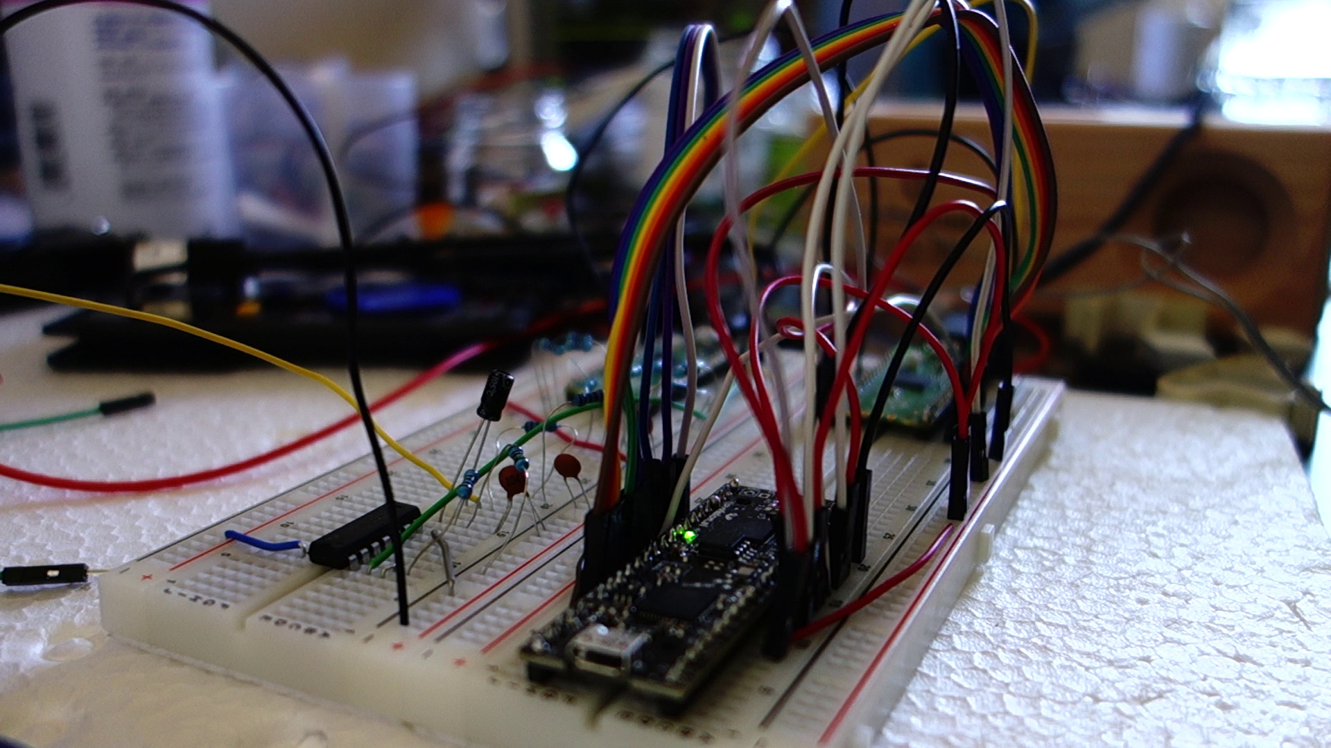
The Raspberry Pi Pico is very good at IO. Not only do we have a lot of pins, but we can read from and write to them very, very fast. However, we aren’t going to go that fast today actually. Neither are we going to be using a lot of pins. In order to build a DAC, we need to read the CLOCK φ1, SD (DATA) and SAM1 and/or SAM2 pins. And then we need output, which in my case is a single pin outputting PWM audio. (It sounds okay, probably not exactly Hi-Fi.) My implementation only reads SAM1 and only outputs a single channel, completely discarding the other channel. It wouldn’t be too hard to get the second channel to work too — the Pico is a dual-core jobby after all, so you could just run the same code on the second core and it’d work. (As there isn’t really a lot of post-processing going on at all, you could most likely even get it to work with just a single core, but I haven’t tried.)
So, in order to test if our DAC, or one of the op amp circuits, or the filter circuits are misbehaving, we just need our Raspberry Pi Pico and check if we’re getting the faulty audio there too. If yes, the DAC is innocent. If no, the DAC or related circuitry would be implicated.
PWM audio
Researching PWM audio on the Pico, I first came across this YouTube video: https://www.youtube.com/watch?v=rwPTpMuvSXg. It turns out, however, that PWM audio is discussed in https://datasheets.raspberrypi.com/rp2040/hardware-design-with-rp2040.pdf, and the creator of the above YouTube video had mostly taken the circuit from there. Basically, you need a medium-sized capacitor to remove the DC bias, some resistors and smaller caps to filter out high-frequency components, and optionally a buffer IC. It’s all right to use a digital buffer IC (I’m using a 74-series logic hex inverter), which then drives the above-mentioned resistors and caps. (The Pico can’t output a lot of current, so I decided to include the buffer, as recommended in the PDF.)
Overview
Since the MSX and its audio module and the keyboard are museum exhibits, and the museum isn’t exactly next door (fortunately not too far away though), I only had limited time to experiment with the original hardware. So what do you do in such a case? Well, I think we all agree that any sane person would immediately head to the internets and check if anyone’s ever implemented the YM2151 (the FM synthesis chip) on an FPGA. (Well, any sane person who owns an unused FPGA. Mine is an UPduino that I bought a couple years ago. They’re actually more expensive now than back then.) As a bonus, if it turns out that the DAC is fine, we should (sometime in the future) be able to hook up our FPGA to the SFG-01 and see if it produces the same weird distorted sound. If it doesn’t, we can be reasonably sure that the YM2151 on the SFG-01 is the one causing the weird sound. (Assuming there are no bad solder joints, etc.)
It turns out that the the YM2151 does indeed exist in the form of Verilog code: https://github.com/jotego/jt51. Amazing! Thank you very much. Impressive. 😳 So all we have to do is:
Put this on our FPGA
Find a way to control the FPGA
Connect the FPGA’s output to our DAC and experiment until it sounds okay
There were many hours spent debugging this. How do you even debug audio that sounds wrong somehow? Well, as with all debugging, you break things up into smaller things that you can actually verify to be correct (or prove incorrect):
Make sure the digital data you are receiving on the Pico is the same as what the FPGA is supposed to be putting on the wire.
Make the FPGA always output the same dummy value. Not the case. The most significant bit is flipped sometimes.
Check if the Pico’s pio_sm_is_rx_fifo_empty() function is lying or something. Yes, looks like it.
Implement a workaround. (More on that later in this post.)
Audio sounds slightly better but overall still crappy.
Forget about the mantissa + exponent algorithms for a second and make the FPGA output straight 16-bit signed PCM.
There’s a hiss but generally speaking it sounds pretty good!
Play around with the PWM audio parameters
Oh wow, the hiss is gone and things sound almost perfect.
Raw PCM audio sounds good, but mantissa + exponent audio still doesn’t.
Make the FPGA output PCM for one sample, and mantissa + exponent of the exact same sample on the next sample.
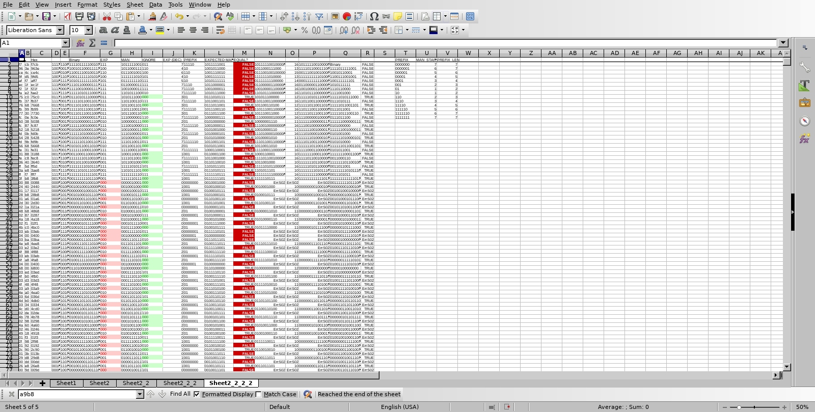
Put a hexdump in a spreadsheet and see if we can spot the problem. The mantissa + exponent samples should be exactly the same (but with some of the lower bits all 0s), but often they’re somewhat different.
Fix some issues that we introduced in the FPGA code
Output changes continuously and must be latched on the first clock cycle of a new sample
reg/wire confusion
Pico DAC’s mantissa + exponent code was slightly wrong too
The thing mentioned in 1-2 could be a bug in the Pico SDK (or documentation). I’ll probably look into that at some point. The workaround consists of reading from the FIFO twice.
Here’s a screenshot of the aforementioned spreadsheet:
The 2d layout, the conditional formatting, VLOOKUP, string processing functions all make it pretty easy to figure stuff out, in my opinion. YMMV. It would have been helpful if LibreOffice’s HEX2BIN could support more than 8 bits, but 8 bits should be enough for anybody, right?
I also used a tiny script (that I’m including below, just for my own convenience for when I need to get back to something related) to convert a hex dump into audio, using xxd and sox:
#!/bin/bash

# assumes a log file generated e.g. like this: minicom -C sample_dump1.log -D /dev/ttyACM0

tail -n +2 $1 > $1.trunc # get rid of hello world debug output
xxd -p -r $1.trunc > $1.trunc.raw
sox -c 1 -r 62000 -t u16 $1.trunc.raw -b 16 -e signed-integer $1.trunc.wav
Pic/audio/video
JT51 running on the UPduino, RaspiPicoVGM running on a Pico (top right) pico_ym3012 running on a Pico (top left)
I obtained a VGM for the YM2151 from this page: https://vgmrips.net/packs/pack/fantasy-zone-ii-dx-sega-system-16c. I chose “10 Years After ~ Cama-Ternya [Demo]”, and converted this from VGM to a header file for use with RaspiPicoVGM using xxd -i. Below is some audio of this VGM being played back using the above pictured setup. Note that it isn’t perfect, most likely due some issues on the FPGA side:
Played on JT51 controlled by RaspiPicoVGM, DAC’d by ym3012_dac
The below video shows the pico_ym3012 connected to the SFG-01 using tiny test clips, fully reproducing the growling/distorted sound that is the source of this whole investigation.
Verilog lessons learned
If you have a `define in one file and an `ifdef in another file, that `ifdef could very well evaluate as true.
Latching is pretty important
Executing always blocks on the correct conditions is pretty important
The synthesis tool won’t always catch wire vs. reg mistakes
Verilator will catch some things that yosys will just interpret in the probably correct way
The code
The code is also available at https://github.com/qiqitori/pico_ym3012/. License is GPLv3 for ten years after release. If there is no update saying something to the contrary, consider it public domain. I have only reproduced the major bits below.
ym3012_dac.c:
#include <stdio.h>

#include "pico/stdlib.h"
#include "pico/multicore.h"
#include "hardware/pio.h"
#include "hardware/uart.h"
#include "hardware/pwm.h"
#include "ym3012_dac.pio.h"
#include "hardware/irq.h"  // interrupts

#define PIN_BASE 0
#define AUDIO_PIN 28

// #define DEBUG 1
// #define JT51 1

#ifdef JT51
#define DESIRED_SAMPLE_RATE 62000 // 4 MHz VGM
#else
#define DESIRED_SAMPLE_RATE 57000 // 315/88 MHz / 2 / 32
#endif

uint16_t samples[110000] = { 0 };
uint16_t last_sample;

int main() {
#ifdef DEBUG
    stdio_init_all();
    sleep_ms(5000);
    printf("Hello world\n");
#endif

    // Init PWM for audio out
    gpio_set_function(AUDIO_PIN, GPIO_FUNC_PWM);
    int audio_pin_slice = pwm_gpio_to_slice_num(AUDIO_PIN);

    // Setup PWM for audio output
    // We run at around 125 MHz. If we set the pwm counter's top value (== wrap value) to 8192 (generally, bigger is better), the pwm counter can reach the top value 15258.7890625 times per second, which would be our effective sample rate. (Calculation: 125000000/8192)
    // However, our target sample rate is larger than that. Let's say if we wanted 44100 Hz: 125000000/44100 = 2834.46712018, so that's the max top value we should set.
    // However, our target sample rate is even larger than that. Let's say we want 60 KHz. Then the max top value is 2083.33333333.
    // In that case, our samples' max loudness should be about half that, 1041.66666667.
    // That's pretty close to 1024. That's good.
    // Let's not hard-code this but calculate based on the desired sample rate.
    // Note that the desired sample rate depends on the VGM tune played.
    uint16_t pwm_wrap = clock_get_hz(clk_sys)/DESIRED_SAMPLE_RATE-24; // TODO: Check if -24 actually improves anything (original intent is to buy microcontroller some time to move to the next sample -- if we don't have enough time, pwm_set_gpio_level might not make it in time and the entire next PWM cycle would be played using the level of the previous sample. I think so anyway.)
    pwm_config config = pwm_get_default_config();
    pwm_config_set_clkdiv(&config, 1.0f);
    pwm_config_set_wrap(&config, pwm_wrap);
    pwm_set_gpio_level(AUDIO_PIN, 0);
//     pwm_set_phase_correct(audio_pin_slice, true); // TODO: maybe test if this changes anything?
    pwm_init(audio_pin_slice, &config, true);

    // Init state machine for PIO
    PIO pio = pio0;
    uint sm = 0;
    uint offset = pio_add_program(pio, &ym3012_dac_program);
    ym3012_dac_init(pio, sm, offset, PIN_BASE);

#ifdef DEBUG
    for (int j = 0; j < 15; j++) {
        for (int i = 0; i < 110000; i++) {
            samples[i] = ym3012_dac_get_sample(pio, sm);
        }
        for (int i = 0; i < 110000; i+=8) {
            printf("%04x %04x %04x %04x %04x %04x %04x %04x\n", samples[i], samples[i+1], samples[i+2], samples[i+3], samples[i+4], samples[i+5], samples[i+6], samples[i+7]);
        }
    }
#else
    while (true) {
        last_sample = ym3012_dac_get_sample(pio, sm); // same as above
//         printf("%04x\n", last_sample);
        last_sample = last_sample >> 5;

        pwm_set_gpio_level(AUDIO_PIN, last_sample);
    }
#endif
}
ym3012_dac.pio:
.program ym3012_dac

; // WARNING you need to switch between JT51/YM2151/PCM code yourself by commenting/uncommenting the relevant PIO code blocks below!

; for man+exp (YM2151):
    set x, 12            ; Preload bit counter, delay until eye of first data bit
    wait 1 pin 1        ; Wait for SAM HIGH // WARNING WARNING WARNING WARNING WARNING WARNING WARNING WARNING change required on JT51: wait 0 pin 1
    wait 0 pin 1        ; Wait for SAM LOW // WARNING WARNING WARNING WARNING WARNING WARNING WARNING WARNING change required on JT51: wait 1 pin 1
    ; ignore first three bits, as specified in data sheet
    wait 1 pin 2        ; Wait for clock HIGH
    wait 0 pin 2        ; Wait for clock LOW
    wait 1 pin 2        ; Wait for clock HIGH
    wait 0 pin 2        ; Wait for clock LOW
    wait 1 pin 2        ; Wait for clock HIGH
bitloop: ; Loop x times
    wait 0 pin 2        ; Wait for clock LOW
    wait 1 pin 2        ; Wait for clock HIGH
    in pins, 1          ; Sample data
    jmp x-- bitloop     ;

; for JT51 linear signed 16-bit PCM:
; for linear s16:
;    set x, 15            ; Preload bit counter
;    wait 0 pin 1        ; Wait for SAM HIGH
;    wait 1 pin 1        ; Wait for SAM LOW
;bitloop: ; Execute following code x+1 times
;    wait 1 pin 2        ; Wait for clock HIGH
;    in pins, 1          ; Sample data
;    wait 0 pin 2        ; Wait for clock LOW
;    jmp x-- bitloop     ;

% c-sdk {
#include "hardware/clocks.h"
#include "hardware/gpio.h"

// #define YM3012_CLK 2000000 // for 4 MHz tunes
#define YM3012_CLK 1790000 // SFG-01 runs at NTSC speed
#define CLK_MULTIPLIER 8 // we need to run faster because we do "wait 1"/"wait 0"s for every transition in PIO code (and have some other extra instructions too)
#define NEGATE_EXP 1
// #define LINEAR_PCM_S16_INPUT 1
// #define DEBUG 1

static inline void ym3012_dac_init(PIO pio, uint sm, uint offset, uint pin_base) {
    pio_sm_set_consecutive_pindirs(pio, sm, pin_base, 3, false);
    pio_gpio_init(pio, pin_base);

    pio_sm_config c = ym3012_dac_program_get_default_config(offset);
    sm_config_set_in_pins(&c, pin_base);
    // Shift existing values to the right when new value comes in
    // The YM3012 receives D0 first, which is the least significant bit
#if LINEAR_PCM_S16_INPUT
    sm_config_set_in_shift(&c, true, true, 16); // signed 16-bit linear, shift to right
#else
    sm_config_set_in_shift(&c, true, true, 13); // man+exp, 10+3 bits, shift to right
#endif
    sm_config_set_fifo_join(&c, PIO_FIFO_JOIN_RX); // appears to be necessary??
    float div = (float)clock_get_hz(clk_sys) / (YM3012_CLK*8); // TODO: 4 * actual clock rate would be nice // "For example, the YM2151 internally divides the clock by 2, and has 32 operators to iterate through. Thus, for a nominal input clock of 3.58MHz, you end up at around a 55.9kHz sample rate." https://github.com/aaronsgiles/ymfm/blob/main/README.md
    sm_config_set_clkdiv(&c, div);

    pio_sm_init(pio, sm, offset, &c);
    pio_sm_set_enabled(pio, sm, true);
}

static inline uint16_t ym3012_dac_get_sample(PIO pio, uint sm) {
    // 10-bit read from the FIFO (data is left-justified)
    uint16_t data_and_exp, data, result, leading_ones;
    uint8_t exp;
    io_rw_32 *rxfifo_shift = (io_rw_32*)&(pio->rxf[sm]);
    while (pio_sm_is_rx_fifo_empty(pio, sm))
        tight_loop_contents();
    uint16_t rxfifo_contents = *rxfifo_shift; // HACK. If we don't read this twice we may get a stale?? value with the last bit sometimes missing. (HOWEVER reading thrice we get something stale again. Though maybe we're just a little late when reading the third time?) (see example below)
#ifdef LINEAR_PCM_S16_INPUT
#ifdef DEBUG
    return (uint16_t)((int16_t)(*rxfifo_shift >> 16)); // don't want that ugly offset when we're debugging
#else
    return (uint16_t)((int16_t)(*rxfifo_shift >> 16)+32768);
#endif // DEBUG
#else // !LINEAR_PCM_S16_INPUT:

    data_and_exp = (uint16_t)(*rxfifo_shift >> 19);

#ifdef NEGATE_EXP // not needed on JT51
    exp = ~((data_and_exp) >> 10) & 0b111; // top 3 bits, negated
#else
    exp = ((data_and_exp >> 10) & 0b111); // top 3 bits
#endif

    data = data_and_exp & 0b1111111111; // lower 10 bits
    if (exp == 0) { // probably doesn't happen on the JT51 at least, and shouldn't happen on YM2151 according to datasheet
        result = 0; // according to jt51_exp2lin.v
    } else {
#ifdef JT51
        result = (data << (exp-1));
        // For signed numbers (first bit of mantissa is 1) we need to sign extend by adding a bunch of ones.
        // The number of ones to be added is: 16 (because uint16_t) - (left_shift_amount (== exp-1) + 10 (mantissa length)).
        // We can create a value with the specified number of leading ones by left shifting a value that is all ones.
        // We need to shift by (16-number_of_desired_leading_ones) (e.g., 0xffff with 16 leading ones can only be achieved by left shifting by 0).
        // 16 - (16-((exp-1)+10)) = 16 - (16 - (exp-1) - 10) = 0 - -(exp-1) - -10 = (exp-1) + 10 = exp + 9
        leading_ones = 0xffff << ((exp-1) + 10);
        if (data & (1<<9)) // test for first bit of mantissa
            result |= leading_ones; // add leading ones
        result = (int16_t)result + 32768;
#else
        result = data << 6;
        result = result / (2<<(exp-1));
#endif
    }

    // related to above HACK:
    // example output of below printf demonstrating the stale output when reading the first and third times
    // first read: 0
    // third read: 715653120 or 2863136768
    // second read (>> 19): always 5461
//     0 715653120 5461 341 2 170
//     0 2863136768 5461 341 2 170
//     0 2863136768 5461 341 2 170
//     0 715653120 5461 341 2 170
//     0 2863136768 5461 341 2 170
//     0 2863136768 5461 341 2 170
//     0 715653120 5461 341 2 170
//     0 715653120 5461 341 2 170
//     0 715653120 5461 341 2 170
//     0 2863136768 5461 341 2 170
//     printf("%u %u %u %u %u %u\n", rxfifo_contents, *rxfifo_shift, data_and_exp, data, exp, result);

    return result;
#endif // LINEAR_PCM_S16_INPUT
}
%}
The scaffolding is basically the same as usual. See the Github repository for details.
I will upload the changes necessary to run the JT51 as a drop-in replacement of a real YM2151 relatively soon. Things aren’t 100% ironed out yet.
Update 2023/03/06
The below update states that there are errors in jt51_phrom and jt51_exprom.v, but these errors were minor and have been fixed. However, the fixed jt51_phrom.v doesn’t appear to have a large effect on the final number of LUT4s used. It looks like the mistake I had originally made (a race condition-type of mistake) was responsible for the majority of the savings. Boo.
Here’s a short sound recording with the mistake left in:
And here’s a short sound recording with the mistake ironed out:
In addition, the changes to jt51_sh.v mentioned in the below update might suffer from some problems too. So far I have only managed to run with jt51_sh8 enabled, so I have no way to compare the unmodified jt51_sh implementation to my modified implementation, but I also tried adding jt51_sh10 for another shift register, and that made things sound rather weird. It’s currently not clear to me why that is the case.
Important update 2023/03/01
I finally managed to test the modified code. Do not use it, there are probably errors in it. Using the modified sine tables (jt51_phrom.v) causes everything to sound noisy. Using the modified exprom.v messes something up, but the effect is rather subtle.
Instead, you can save on LUTs by modifying jt51_sh.v as follows. This is the original code:
module jt51_sh #(parameter width=5, stages=32, rstval=1'b0 ) (
    input                           rst,
    input                           clk,
    input                           cen,
    input       [width-1:0]         din,
    output      [width-1:0]         drop
);

reg [stages-1:0] bits[width-1:0];

genvar i;
generate
    for (i=0; i < width; i=i+1) begin: bit_shifter
        always @(posedge clk, posedge rst) begin
            if(rst)
                bits[i] <= {stages{rstval}};
            else if(cen)
                bits[i] <= {bits[i][stages-2:0], din[i]};
        end
        assign drop[i] = bits[i][stages-1];
    end
endgenerate

endmodule
It looks like the logic yosys synthesizes from this code is inefficient. I haven’t looked too much into it, but writing this code out (and removing one of the channels, etc.) causes yosys to synthesize more efficient code. As you can see, this code uses parameters that affect the way it is generated. I just picked one set of parameters that appeared multiple times, width=14 and stages=8, and that was enough to get the logic to just fit. I.e., I appended the following code inside the same file:
And adjusted jt51_op.v to use jt51_sh8 instead of jt51_sh for prev1_buffer, prevprev1_buffer, and prev2_buffer.
Original post follows:
Quick summary
I took JT51 (https://github.com/jotego/jt51) and shrunk it down a little. I got it down to just barely fit. There are some lookup tables that are processed down by a couple hundred LUT4s, I made the lookup tables contain the already processed values instead. We’re now using slightly more RAM.
How we got here
I am currently debugging a YM2151-based device, the Yamaha SFG-01 sound module for MSX PCs. There is… wonky audio when two notes are played at once on the attached keyboard. I started off by emulating the YM3012 DAC on a Raspberry Pi Pico. More on that in a future post. More on the whole repair in a future post, in fact. My plan was to run the original YM2151 and the FPGA version side-by-side (with the exact same inputs) and to compare the audio outputs. However, after I already did most things detailed in this post, I realized that plan probably wasn’t going to work, as (if I read the datasheet correctly) the YM2151 generates interrupts which probably have to be acknowledged, and the data bus is bidirectional, and actually does get read out by the CPU occasionally. So the original chip and the FPGA would have to work in 100% perfect sync, and who knows how achievable that is.
I have two FPGA boards, and they’re both exactly the same, UPduino v3.0. I bought these back in 2020 or so, expecting I’d maybe come up with a project at some point. They were cheaper back then! I paid 43.20 USD + 6 USD shipping for 2! So per device, in JPY at that time: 21.6 * 103 = 2225 JPY. Currently, the price is $30 per device, and USD/JPY is 133.8. 30 * 133.8 = 4014 JPY, so almost double. Yikes.
Only have an ICE40UP3K? Allegedly, if you use the open-source toolchain, it’ll have exactly the same amount of LUT4s available as an ICE40UP5K. Apparently it’s just the official IDE enforcing an artificial limit?
So all I’d done up to this point was: I installed the open-source toolchain, changed the speed of the LED blinking example, re-flashed, and got some satisfaction that it all worked. Let’s start from that point. I think the official tutorials should get you there (except for the speed change maybe).
Also: important: I haven’t tested my revised Verilog yet. That’s something for part 2 (not done/written yet).
Then, git clone https://github.com/jotego/jt51. Copy UPduino-v3.0/RTL/common from the toolchain to jt51/ and UPduino-v3.0/RTL/blink_led/Makefile to jt51/hdl/. Perhaps cd to jt51/hdl and modify the Makefile as follows.
Note: Makefiles consist of rules laying out how to build a certain file. Rule blocks start like this: “filename: dependencies”. The dependencies are filenames. There is only one rule in our Makefile that directly depends on .v files:
rgb_blink.json: rgb_blink.v
Instead of rgb_blink.v, we’ll replace that by all the jt51_….v files we have in jt51/hdl:
And finally, let’s change all names from “rgb_blink” to “jt51” using search and replace: “rgb_blink” -> “jt51”. You should end up with a Makefile like this:
# Makefile to build UPduino v3.0 rgb_blink.v  with icestorm toolchain
# Original Makefile is taken from:
# https://github.com/tomverbeure/upduino/tree/master/blink
# On Linux, copy the included upduinov3.rules to /etc/udev/rules.d/ so that we don't have
# to use sudo to flash the bit file.
# Thanks to thanhtranhd for making changes to thsi makefile.

rgb_blink.bin: rgb_blink.asc
	icepack rgb_blink.asc rgb_blink.bin

rgb_blink.asc: rgb_blink.json ../common/upduino.pcf
	nextpnr-ice40 --up5k --package sg48 --json rgb_blink.json --pcf ../common/upduino.pcf --asc rgb_blink.asc   # run place and route

rgb_blink.json: rgb_blink.v
	yosys -q -p "synth_ice40 -json rgb_blink.json" rgb_blink.v

.PHONY: flash
flash:
	iceprog -d i:0x0403:0x6014 rgb_blink.bin

.PHONY: clean
clean:
	$(RM) -f rgb_blink.json rgb_blink.asc rgb_blink.bin
Make sure you have tab characters, not space characters in the rule block indentation. (Trap for young players.) Make sure you also copied the common/ directory as instructed above. Then, execute “make”. If you get the following error:
$ make
nextpnr-ice40 --up5k --package sg48 --json jt51.json --pcf ../common/upduino.pcf --asc jt51.asc   # run place and route
/bin/sh: 1: nextpnr-ice40: not found
make: *** [Makefile:12: jt51.asc] Error 127
That means you need nextpnr-ice40 in your PATH. Figure out the path, and then execute:
Okay, first things first. How old is our toolchain?
$ yosys -V
Yosys 0.8 (git sha1 5706e90)
Let’s see, the newest version of yosys, at the time of this writing, is… 0.26. Wait what? Ah, it looks like a smaller number, but is probably intended to be a larger number. It appears that my version is from 2018. Likely, I’d just installed it from Debian’s repositories. Let’s try building yosys from Git so we can upgrade from 0.8 to 0.26. It would like to build using clang by default, but you can build using gcc too. You also need tcl8.6-dev (or probably other versions work fine too).
$ git clone https://github.com/YosysHQ/yosys
$ cd yosys
$ make
/bin/sh: 1: clang: not found
[  0%] Building kernel/version_4c334b905.cc
[  0%] Building kernel/version_4c334b905.o
/bin/sh: 1: clang: not found
make: *** [Makefile:754: kernel/version_4c334b905.o] Error 12
$ make config-gcc
...
In file included from kernel/calc.cc:24:
./kernel/yosys.h:81:12: fatal error: tcl.h: No such file or directory
 #  include <tcl.h>
...
$ sudo apt-get install tcl8.6-dev
...
$ make config-gcc
...
$ # success
And if we try synthesizing again now, we do get a significant improvement. (Also synthesis time is faster I think.) But we are not quite there yet:
Shrinking the footprint by changing yosys options (using DSP cells)
110% isn’t too far from where we need to be, so let’s investigate if we can do anything to reduce our FPGA footprint. First of all, there are three files that include the word ‘rom’, which may have a significant effect on our footprint. But it looks like our toolchain is clever — it actually uses ICESTORM_RAM to implement the ROM. (Replacing the entire case/endcase block in the rather large jt51_phinc_rom.v file with a single statement reduced the LC count by 2-3%, and ICESTORM_RAM from 10% to 0%.)
Next, we forget about yosys for a second, and attempt to synthesize this using the official toolchain from Lattice, IceCube2. You’ll need an account and follow a link to generate a license file. You need to enter a MAC address to bind the license to a certain computer. (Or maybe a computer with a certain network adapter.)
IceCube2’s synthesis finishes in a few seconds, and only uses 11 logic cells. Hmm, so efficient! Or more likely, something’s weird. And yes, indeed it’s getting confused and thinks that jt51_noise_lfsr.v is the main file. Apparently, this file’s modules aren’t actually used anywhere. So we get rid of that file (and also get rid of it in our Makefile above) and re-synthesize. Synthesis finishes successfully, and apparently uses 1698 LUTs. Hmm, really? (No, but let me go off a quick tangent first.)
Okay, let’s assume for a second that yosys is much, much worse than IceCube2. It’s time to google for something like ‘yosys vs icecube2’. A person on the EEVblog forums says, “The IceCube2 generates smaller and faster design (most visible with larger designs) than the IceStorm does, it can infer ie. multipliers with built-in DSP modules (UP5k) etc. The IceStorm is less effective, and infers ie. multipliers in fabric (you have to instantiate the modules/primitives manually).” Hmm, interesting. Well, it turns out you can enable the DSP modules in yosys using the -dsp option, so we modify the Makefile as follows:
That reduces our LUT count by ~2% percent. Every percent counts, but we’re not quite there yet. Looking at https://github.com/YosysHQ/yosys/blob/master/techlibs/ice40/synth_ice40.cc, we see a few more options we could try, e.g., -spram, -noabc, -abc2, -abc9 (experimental), -flowmap (experimental).
-noabc brings us back up to 120%. -flowmap also increases the number of logic cells to a similar number. -abc2 eliminates 19 logic cells vs. just -abc, but that’s not a lot, and our percentage doesn’t change. -abc9 doesn’t yield much of an improvement either. Hmm, looks like we’ve exhausted some of the lower hanging fruit. Anyway, let’s take another closer look at the official toolchain’s output. When your eyes get a little more used to its output you actually notice that it says:
Hey. 1698 LUTs, but 3825 DFFs, and the P&R Flow tool confirms this:
Number of LUTs      :   1698
Number of DFFs      :   3825
Number of Carrys    :   366
These DFFs also use up LUTs, so the total number of LUTs used is 5523, which is actually extremely close to yosys, and also too much. (Note that I already edited the Verilog a little bit at this point, so the number on an unmodified repository would be a little higher.)
Let’s remove the -q option from yosynth’s synth_ice40 command in the Makefile, and take a look at the output close to the summary that we looked at before. Scrolling way past a lot of verbose output, we get a summary like the following, and can see that yosys is indeed very close.
Info: Packing constants..
Info: Packing IOs..
Info: Packing LUT-FFs..
Info:     1462 LCs used as LUT4 only
Info:      515 LCs used as LUT4 and DFF
Info: Packing non-LUT FFs..
Info:     3367 LCs used as DFF only
Info: Packing carries..
Info:      184 LCs used as CARRY only
Info: Packing indirect carry+LUT pairs...
Info:       63 LUTs merged into carry LCs
Shrinking the footprint by removing features
Next, we could try and cut down on features in order to reduce the required number of logic cells. First of all, I nuked the entire right channel (“right” and “xright”) by commenting out a couple lines in jt51.v and jt51_acc.v. That shaved off about 2%. I kept “xleft” but also got rid of the converted “left”. That means we no longer need to compile jt51_exp2lin.v, which seems to save 9 LUTs.
Shrinking the footprint by trading LUTs for RAM
A cursory (liar liar pants on fire) glance over the code revealed an opportunity to potentially save a more significant number of LUTs. In jt51_op.v, we refer to a sine table (which is in jt_phrom.v) and concatenate certain bits from this table. In the following snippet, the sine table is already in the sta_XI register:
If you are new to Verilog, numbers often look like this: <total bit width>'<letter indicating number format, e.g., b for binary><number>. The array indices refer to bit numbers. E.g., sta_XI[38] is bit 38 in sta_XI, counting from 0. “case” is like a switch statement in C. So up here, we do something like:
switch(bits 7 and 6 of phaselo_XI) {
    case 0: ...;
    case 1: ...;
    case 2: ...;
    case 3: ...;
    default: ...;
}
(The “default” clause is extraneous, but doesn’t cause harm.)
The sine table is fairly large, at 32 entries of 46 bits. In the above code snippet, we pick (to me, super random) bits from the table and also insert constant 0s and 1s here and there. E.g., the first line reads in plain words: ten 0s, followed by sinetable[i][29], followed by sinetable[i][25], followed by two 0s, etc. The sine table isn’t used anywhere else.
Our opportunity is: instead of generating a circuit to combine bits from the sinetable together, we can just rewrite the sine lookup table to already contain what we call stb above. It doesn’t matter if our table ends up a little larger (it could be up to four times larger), because as mentioned above, RAM is used to store these tables. But our table isn’t that much larger, really. Before we had 32×46=1472 bits, now we have a three-dimensional array of dimensions 4x32x19=2432 bits, not even twice as large.
This optimization takes us to 5363/5280 (101%), which means we’re almost done! (If we use four two-dimensional arrays and a case block, the savings are much less pronounced, 104%.) Of course, there is no free lunch: we now use more RAM: ICESTORM_RAM 5/30 (16%). Before it was 3/30 (10%). But we still have a lot of RAM left.
Rewriting the table by hand presumably gets old quickly, so I wrote a short Perl script to do it. (Luckily, it can sometimes be very easy to transform Verilog source code to Perl using find and replace with regular expressions.)
We could actually go even further; looking a little further ahead, stb is only used to fill in stf and stg:
    stf = { stb[18:15], stb[12:11], stb[8:7], stb[4:3], stb[0] };
    // Gated value to sum; bit 14 is indeed used twice
    if( phaselo_XI[0] )
        stg = { 2'b0, stb[14], stb[14:13], stb[10:9], stb[6:5], stb[2:1] };
    else
        stg = 11'd0;
Which means we could change our lookup table once more and directly read out stf and stg. However, scrolling down a little further in the same file, we see the same kind of pattern in the code doing the post-processing for jt51_exprom, so let’s tackle that one instead. Changing jt51_exprom to directly return etf and etg gets us: 5196/ 5280 (98%). Yay!
Now, if we wanted to make a drop-in replacement for an actual YM2151 chip, we’d have to serialize sound output. JT51 outputs xleft/xright/left/right using 16 IO pins each. (We don’t even have enough IO pins on our FPGA.) But the actual YM2151 uses four pins: clock, SH1, SH2, and SO. SO is the serialized representation of left/right, synced with clock. SH1 is high if SO is currently outputting left, SH2 is high is if SO is currently outputting right. In order to implement that, we need a few more LUTs.
Anyway, that was a rather long-winded explanation. Below is the code. I also have it on https://github.com/qiqitori/jt51. Note that the code hasn’t been tested yet at the time of this writing.
Revised jt51_phrom.v (still GPLv3 or later but the copyright header is a little too big for this space):
The exprom code used [44:36], so we need to reverse that using Perl’s array-reversing function, reverse(). The notation used here (reverse(@{$exp_XII->[$i]}[36..44])) is probably one of the reasons why Perl has fallen out of favor. :)
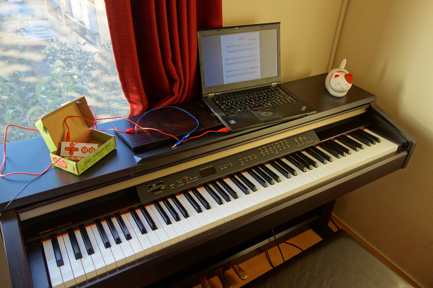
It’s always been a bit awkward for me to play from sheet music that is being displayed on a laptop on top of the piano. I’ve been doing this for a long time, but advancing to the next page is pretty inconvenient. The other day however, I put two and two together and came up with a solution.
For Christmas last year, I got something called “Makey Makey”, a small printed circuit board that acts as a (USB) keyboard (or mouse). You attach two cables to the board, one to ground and the other to a “pin” on the circuit board. When you create a circuit by e.g. letting the other ends of these cables touch one another, a key stroke or click (depending on the selected pin) is sent to the computer. The board has left, right, up, and down, as well as space and click, though if I remember correctly, you can get it to output other key codes too. The idea is that you can use anything to complete the circuit: bananas, Play-Doh, water, or your own body.
Maybe check out this video to get a better idea:
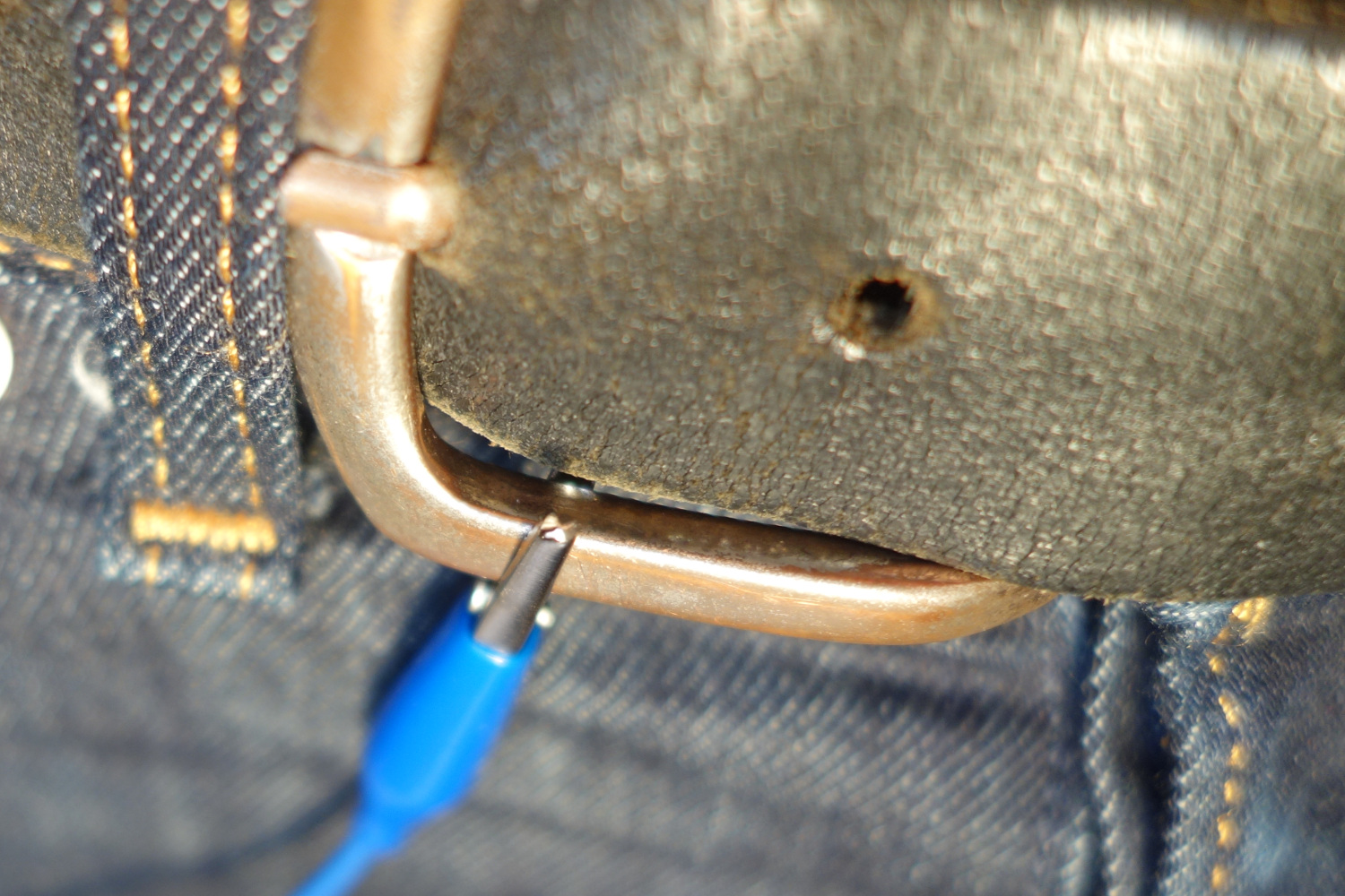
So when playing the piano, your feet, especially your left foot, aren’t very busy. You may have three pedals, but only need one all the time. So can we maybe use the middle pedal to advance our score? Yes, we can! My Clavinova has pedals that are made of metal. (This probably contributed to my idea a bit.) All you have to do is attach one cable from ground on the circuit board to your body (my belt buckle is made of metal and touches my skin). The other cable is attached to the middle pedal. (The cables that come with the kit have alligator clips, which makes this very easy.) Now just take off your left sock (or wear a sock with a hole in it :p). Awesome, by touching the middle pedal, you can scroll down. If you’re lucky, that’s the end of it. But in my case, the other pedals scrolled down too! Apparently my piano’s pedals are all connected to another. Hrm.
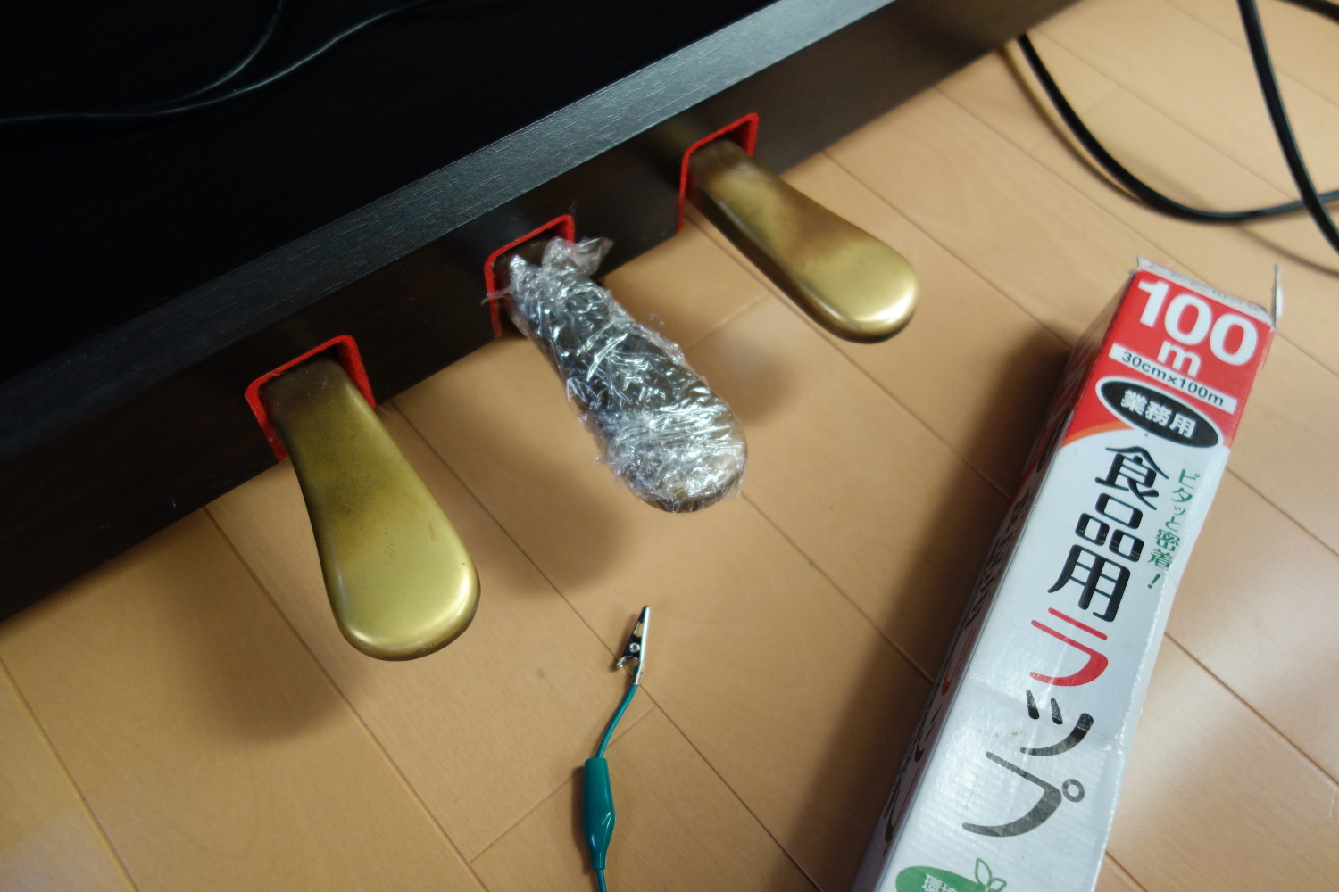
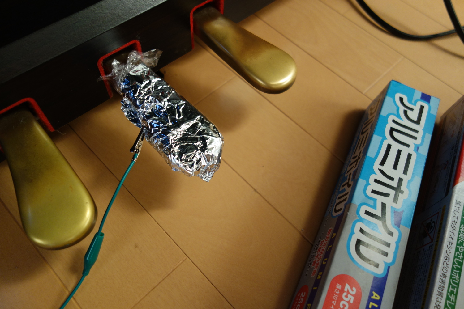
And that’s where you do not give up, but see how you might be able to MacGyver the situation. If you e.g. have sticky tape and a coin, that would work. I didn’t have any tape, but I had plastic wrap and aluminum foil. I first wrapped the pedal with the plastic wrap for electrical insulation, and wrapped the result with the aluminum foil. Then I attached the alligator clip to the aluminum foil, and everything works as planned. Make sure to make a thick bulb of aluminum foil to attach the alligator clip to. Otherwise the alligator clip will just cut through the foil.
There are times when you would also like to be able to scroll back up. I haven’t implemented that yet, but it wouldn’t be hard to divide the middle pedal into an up button and a down button depending on where it was touched.