In a previous post, we talked about the Hitachi MB-H2 and how we found a RAM fault using a two-channel oscilloscope. Fixing this problem made the computer boot. In this post, we’ll talk about a fault in the analog board which prevented cassette playback from working.
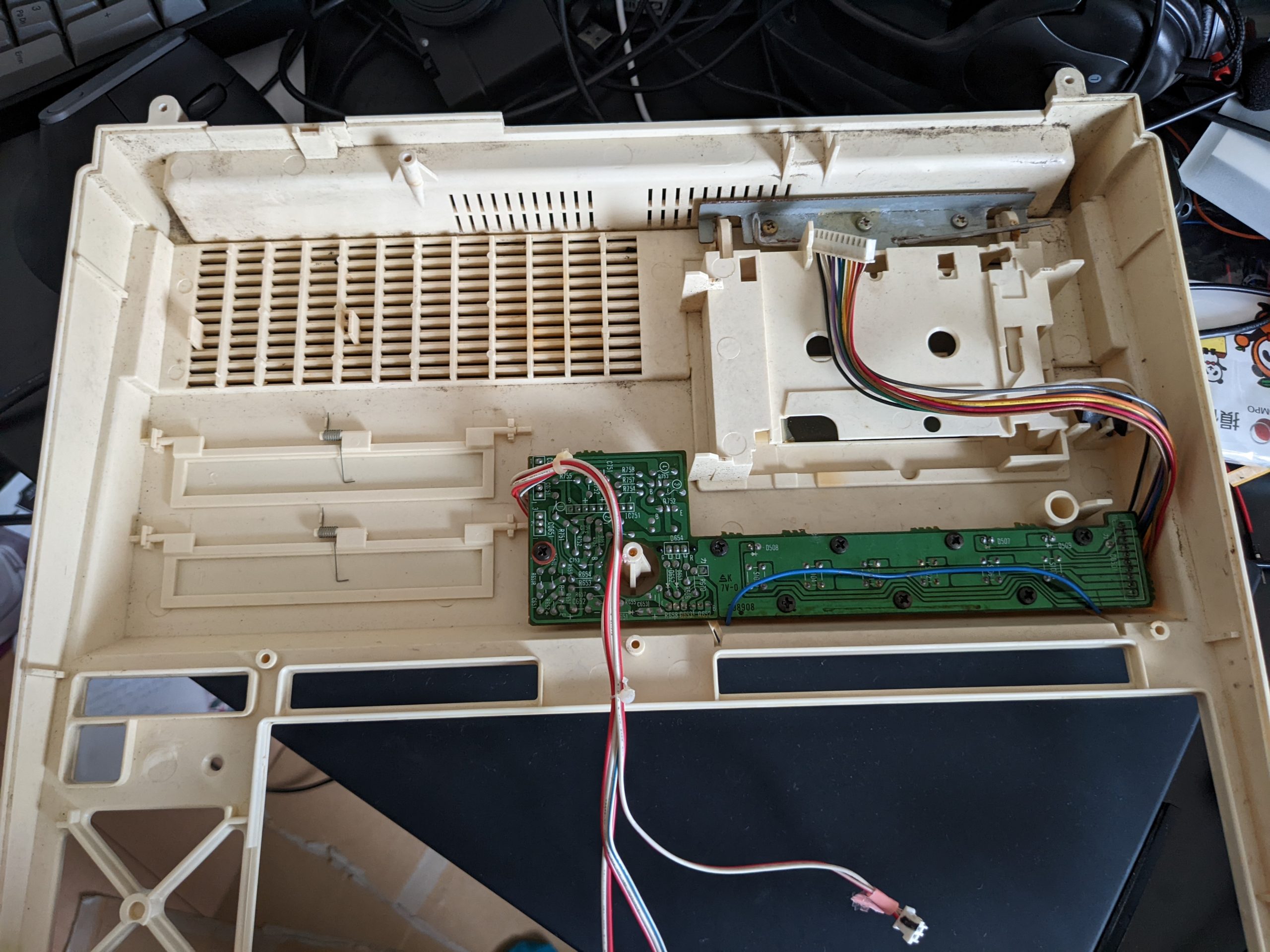
The Hitachi MB-H2 has an integrated cassette deck, which allows both music playback (sounds quite okay even) and data recording. Below are two somewhat high-resolution images of the backside of the analog board with the RF shield removed. This is almost as good as having the schematics (which nobody does AFAIK), because the backside has labels for everything, including transistor orientation and lines indicating how things on the front side are connected, and the traces are relatively easy to see. If you are experiencing problems with the analog board, this may help you, and you won’t even have to get rid of your RF shield or take the board out of the computer (which is pretty annoying).
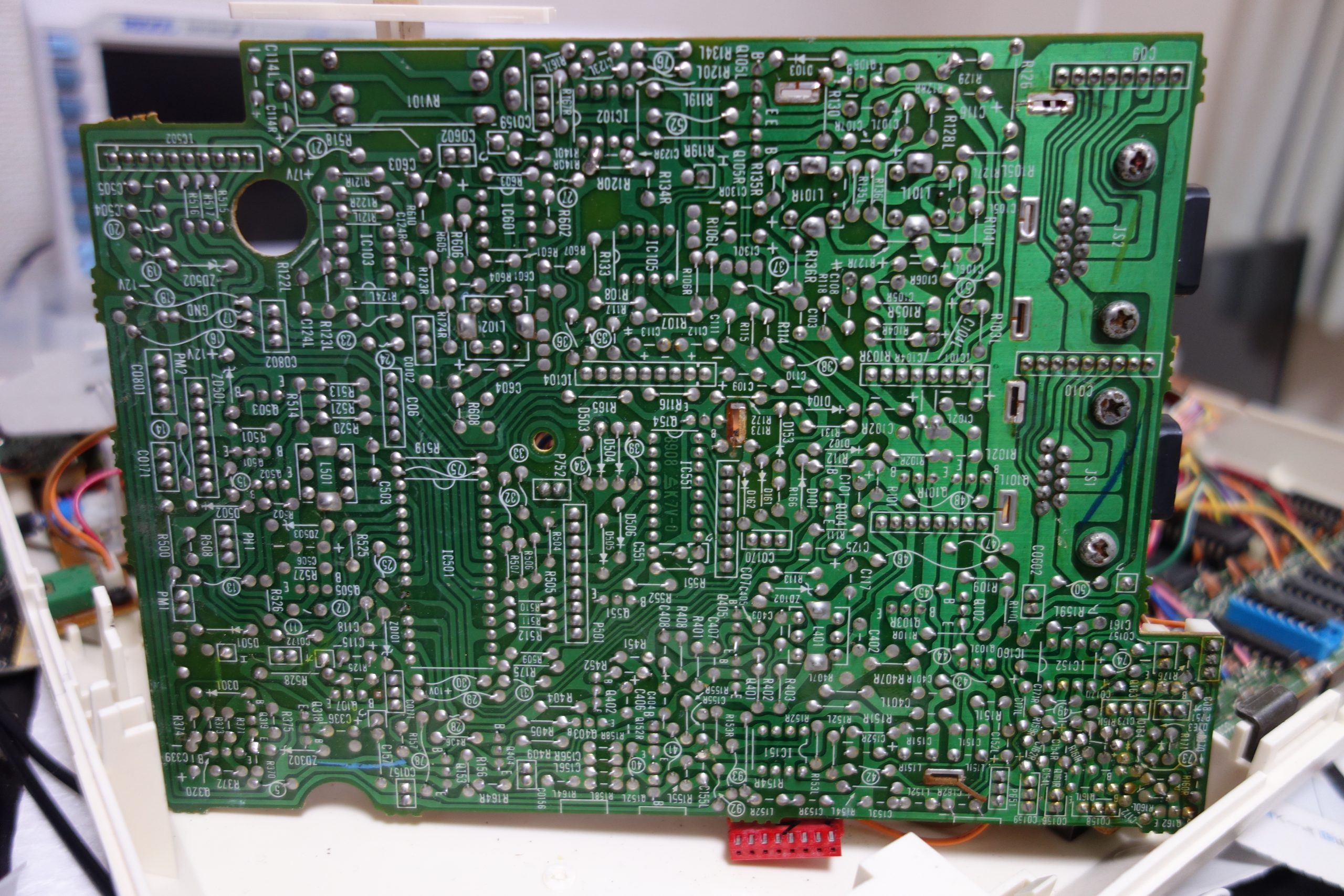
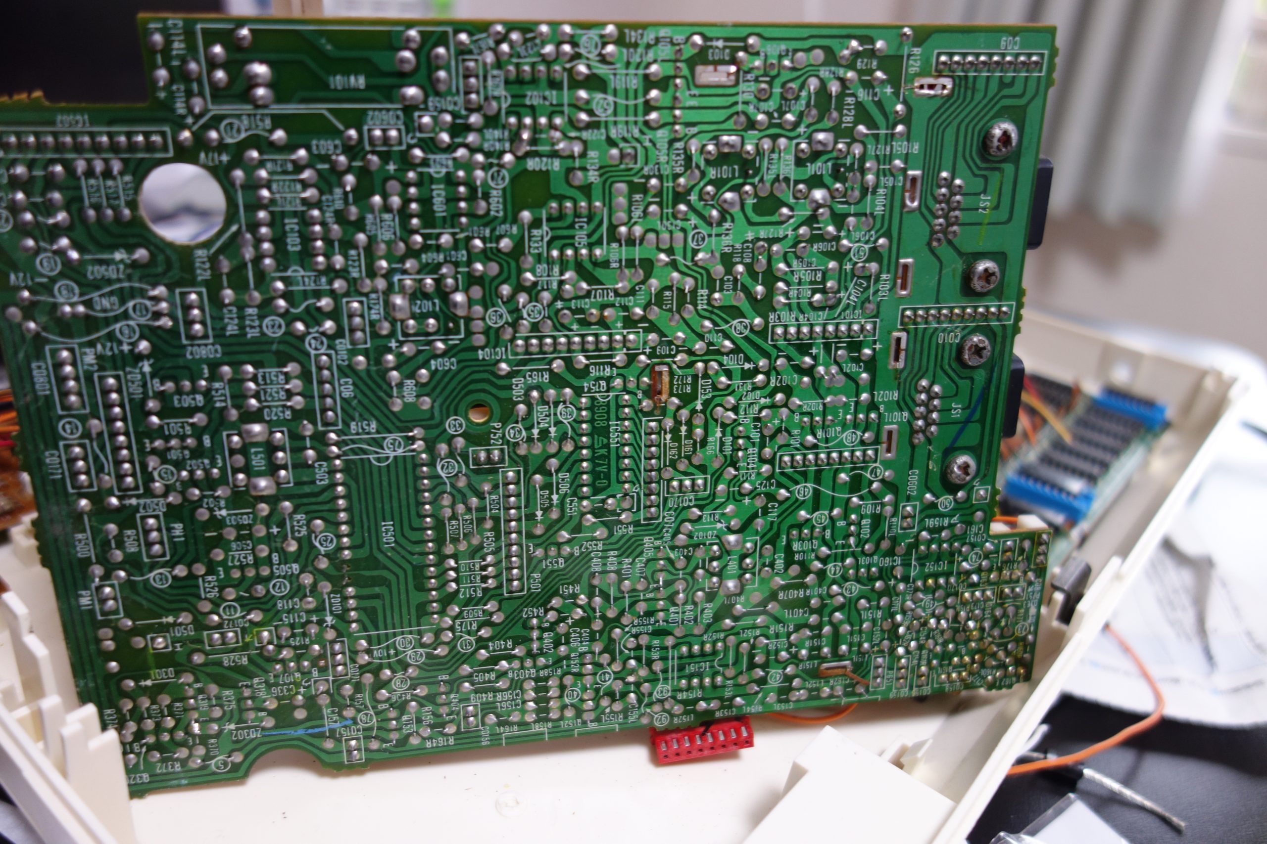
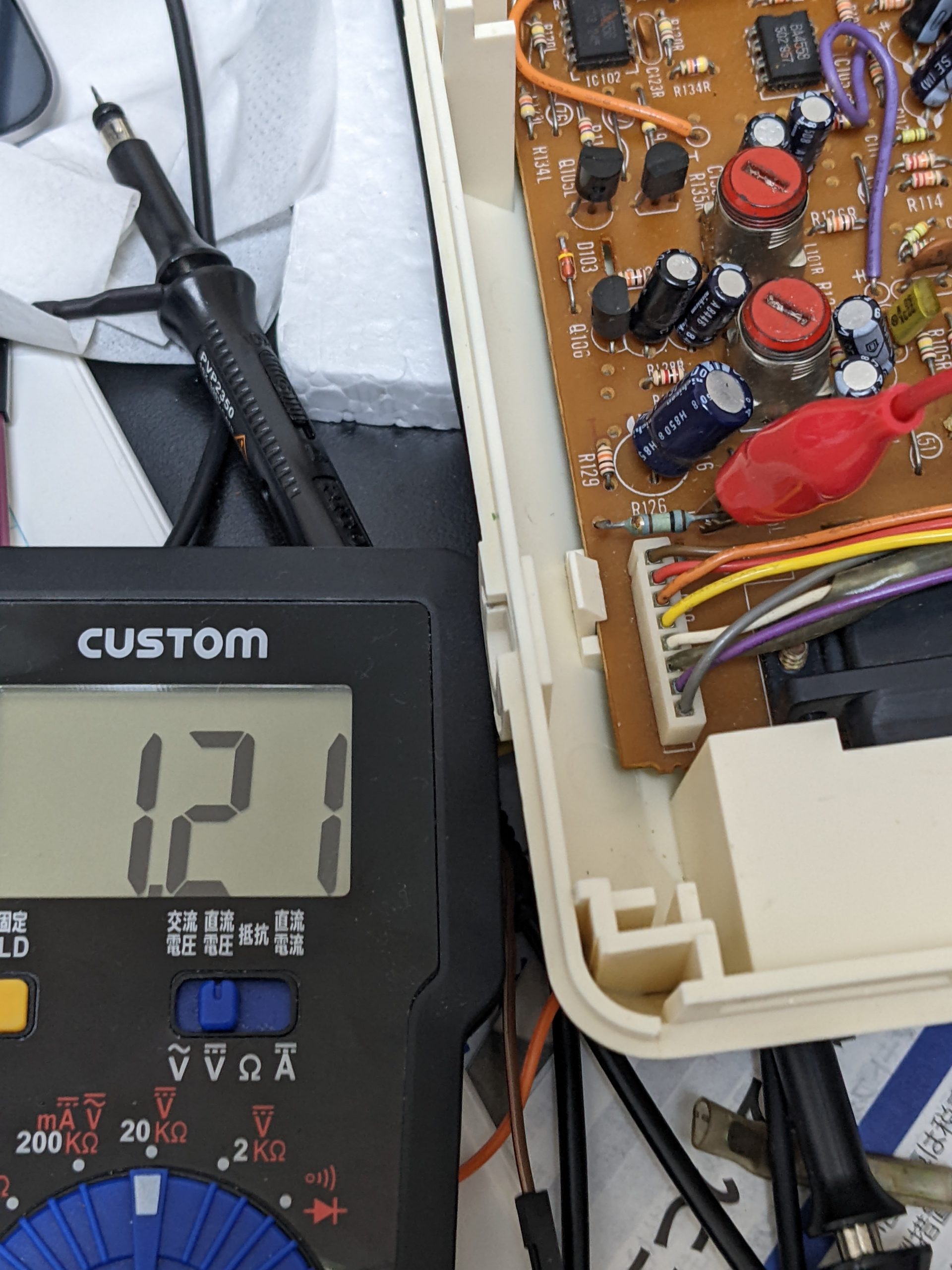
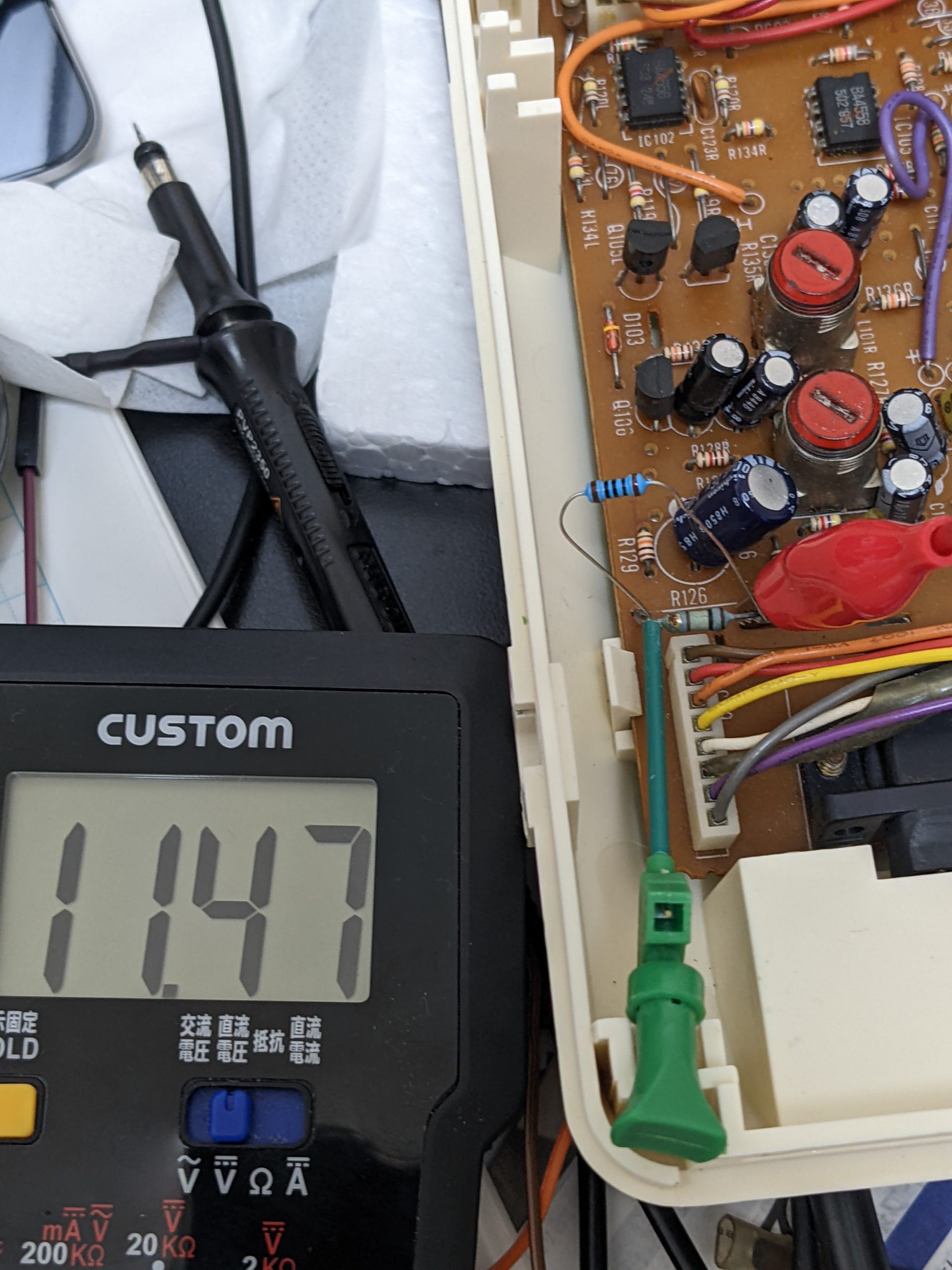
In my case, the pre-amplifier IC (left of the tape head connector when viewed from above) wasn’t getting much voltage, only around 1.21V. This is under the RF shield, but it’s quite easy to follow the trace using the above images. The pre-amplifier’s VCC is on the 12V rail, but there’s a slightly larger than normal 100 ohm resistor (according to the bands) (R126), and a cap to ground between it and the 12V rail. The gold band on my resistor looked slightly thicker than usual, and when I measured it I got 130 kiloohms! (The capacitor’s capacitance and ESR seemed okay still). I replaced the 100 ohm resistor of unknown power rating with a 2W 100 ohm resistor, and immediately playback and loading started working! Yay.
Note: I replaced the burned resistor using a 2W resistor, so it’s unlikely to burn again. (It doesn’t seem to get particularly hot.)
Tape drive mechanism repair and re-assembly
(Disclaimer: I didn’t know much about tape drives going into this)
Somebody before me had removed the belt (probably because it was broken), so I replaced that. I don’t remember the exact length, but this rather cheap set: https://www.amazon.co.jp/gp/product/B08JP7J5VX/ had a belt that fit. (Since the original belt was gone, I don’t know if they have the same thickness as the original belt, but they do feel a little thin maybe.)
Disassembling the tape drive isn’t that hard, but there is more than one way of putting it all back together, and only one way is the correct way! This tape drive has two motors and one electromagnet (blue). One motor is on all the time and drives the capstan roller (IIRC). The other motor only runs when you press play or rewind, etc. (Or issue CALL PLAY etc., from BASIC). The electromagnet exists in order to hold the head mechanism close to the tape. (Or to prevent it from staying in place?) There’s a white plastic piece of plastic that has a hole, and the electromagnet’s pin has to go through this hole. Important: the electromagnet has to be attached to the white plastic piece correctly. The electromagnet is necessary to release the head mechanism when you press stop, and if it isn’t attached correctly, the head mechanism stays attached to the tape. Since the motor driving the roller is running all the time, and thus keeps driving the capstan, but the reel stops, this means your cassette’s tape will be moving, but the cassette’s reels aren’t moving. Your cassette’s tape will be spilled all over the place!
Eject mechanism
The eject mechanism consists of a button (which probably contains a spring, but I wasn’t able to get it out), a metal rod with a 90 degree bend on one side, a piece of metal the rod gets mounted with, some plastic parts (including a spring) that are mounted on the tape mechanism itself, and the lid.
The metal rod would strongly prefer to be a straight rod, but is forced into an unnatural shape by the piece of metal (which needs to be screwed in tight). The metal rod’s bent end goes into a small hole on the piece of metal and the other end presses down on the lid’s hinge. The rod’s tension causes the lid to strongly prefer to be in the “eject” position.
The eject mechanism only works reliably when the computer’s top part of the case is firmly attached to the bottom part, because otherwise the plastic parts mounted on the tape mechanism itself don’t properly hook into the plastic on the eject button. When this is hooked properly, this rod is forced into a slightly more tense state. When you press eject, the lid opens up rather forcefully. Even with everything closed properly, I find that you also have to press rather hard on the tape lid to close it again after ejecting.
Keyboard “repair”
Many of the keys on my machine only worked barely. To get them to work properly, you need cotton swabs and IPA. I strongly recommend you do the cleaning while the computer is powered on (if you don’t short anything unrelated, nothing terrible will happen). Only this way will you be able to get a feeling for how much rubbing is required on your machine. (I had to rub quite hard.)

Edit 2023/06
Edit one year later: Note: I am not a very experienced keyboard repairman! I _think_ that these contacts are just gold-plated copper and rubbing slightly harder won’t damage them, but I do not know for sure! My keyboard works 100% even one year after I did this, but TBH the keys feel very mushy and you have to make them go all the way down to effect a key press. I don’t know what the keyboard was like when it was new. I’ve heard of people using a pencil to put some more conductive carbon on the rubber pad, or rubbing the rubber into a freshly laser-printed black page, and there’s also this type of product here: https://www.ebay.co.uk/itm/REMOTE-CONTROL-REPAIR-KIT-CONDUCTIVE-RUBBER-KEYPAD-FIX-TV-DVD-ALARM-FOB-PHONE-/171656481000
Edit 2023/08
So I tried rubbing the rubber pads on copy paper. This worked brilliantly! Before, I had to push down keys pretty much all the way to effect a keypress, now I can type almost normally. I got this tip from here:
BTW I clean the contacts on the PCB side with isopropanol, and in extreme cases, with an ink eraser. On the rubber side, I gently wipe them on a piece if paper. This takes off a smidgin of the conductive carbon surface, exposing fresh carbon. It can help a lot.
https://ilike8bits.com/what-else-have-i-been-up-to/
Note: You’ll get a grey/black streak on your paper.
(Edits end here)
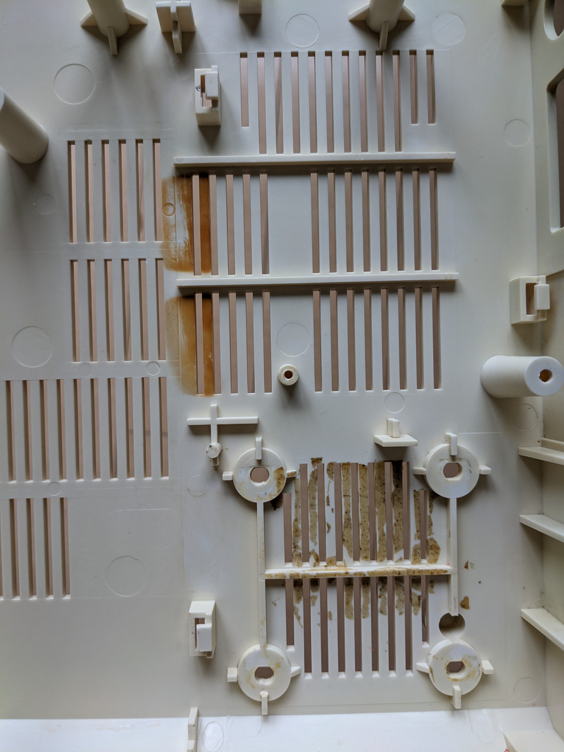
I cleaned the keyboard keycaps using an ultrasonic cleaner. I used lukewarm water and a small amount of dishwashing soap. This worked perfectly. Hint: ultrasonic cleaners can be bought used for pretty cheap. I guess it’s the sort of item people buy because they do clean glasses pretty well, but then rarely use, and eventually get rid of. (I also retrobrighted some of the keys (and the case). Most normal keys were fine, but the space bar, cursor keys, and most of the function keys were yellowed. I used sodium percarbonate and the sun. I’m not an expert on retrobrighting, but this was cheap and worked okay.)
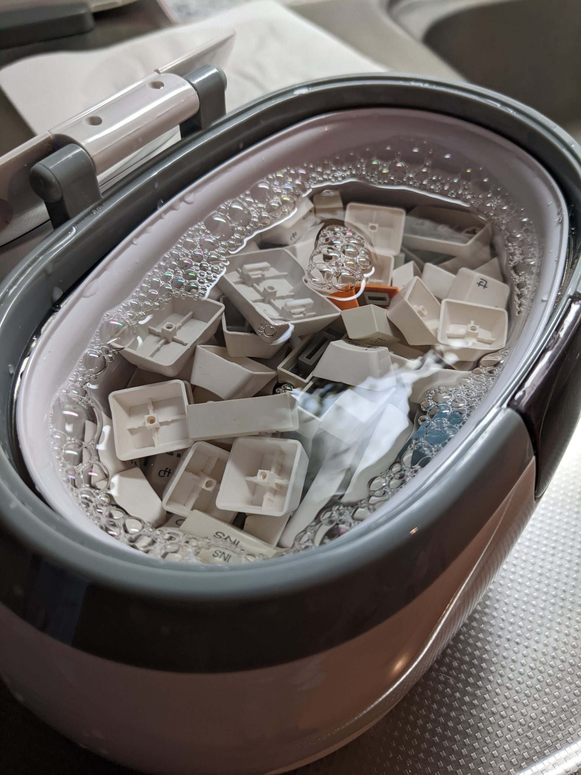
While we’re talking about cleaning, let’s take a look at these two lovely pictures.

Running software
I had a quick look at the prices for used cartridges and decided I don’t want to spend money on software that has been paid for already. (A couple hundred yen would be fine I guess.)
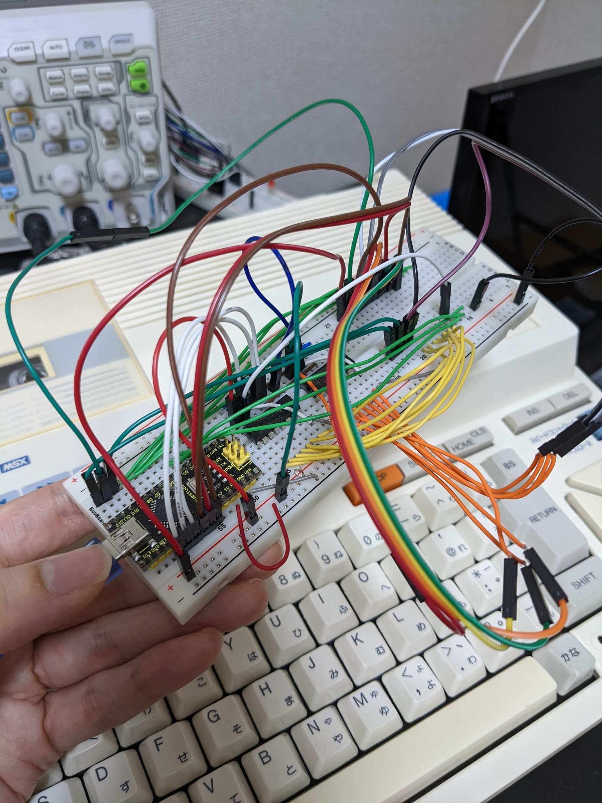
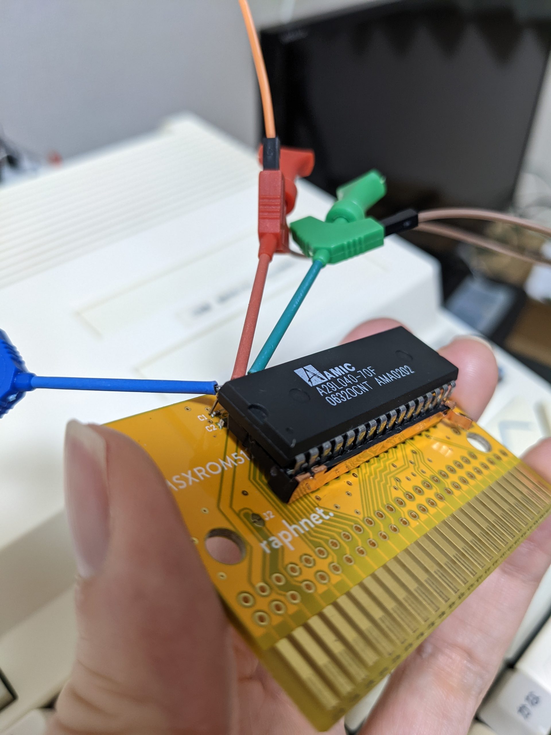
https://www.raphnet-tech.com/products/msx_64k_rom_pcb/index.php caught my attention. Especially as I was able to buy one off Yahoo Auctions without waiting too long. You just need to solder a socket and program an EPROM chip with the game data. Used EPROM chips are super cheap, but as I don’t have an EPROM eraser, I decided to get a Flash EEPROM chip with a similar pinout instead. The Flash EEPROM chip I got is larger (32 pins) than the ones the creator of this board had in mind (28 pins), which means that two address pins, +5 and \WE hang over the edge of the socket. Using conductive tape, I added a “trace” to the side of my socket to hold pins 1 and 2 (A16 and A18) to GND. On the other side, pin 30 (A17) sits where +5 is supplied by the PCB. I could have probably added traces using conductive tape, but since there are two tiny SMD capacitors right under my pin 32, I decided to cut the socket so I wouldn’t apply pressure to the caps, which means that my pin 31 (\WE) and 32 (VCC) are floating in mid-air. I used test clips to connect these to +5. Since A17 is where +5 is located, I have to program my software to 0x24000 instead of 0x4000. I use this to program my Flash EEPROM: https://www.kernelcrash.com/blog/arduino-uno-flash-rom-programmer/. (My Flash EPROM is an AMIC A29040 but works wonderfully with this.) This code appears to have gotten slightly old, I had to change my serial buffer size in HardwareSerial.h by setting:
#define SERIAL_RX_BUFFER_SIZE 256
SERIAL_BUFFER_SIZE (with “_RX_” or “_TX_”) doesn’t appear to be used in this context. At first I also set SERIAL_TX_BUFFER_SIZE to 256, but that appears to break the deploy process, so don’t touch that, I guess. (And yes, if you don’t set the serial buffer size, you won’t be able to write to your EEPROM. You will still be able to identify it though.)
Note the test clips sticking out. Very decorative right?
Man, thanks for the tip on failed resistor! I would have never found it myself.
Interesting, seems like it’s a somewhat common issue then. I got hold of another MB-H2 that didn’t have any problems playing back any sound, but I just measured the resistor and it seems like it’s drifted too. The rings indicate 100 ohms I believe, but it measured about 300 ohms.