HB-10
HB-F900
See https://blog.qiqitori.com/2022/11/sony-hb-f900-repair/.
HB-T7
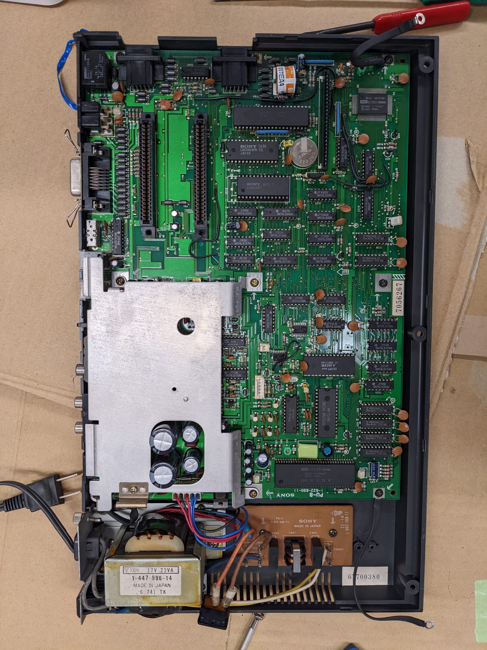
Symptoms: black screen, no sound, no activity whatsoever.
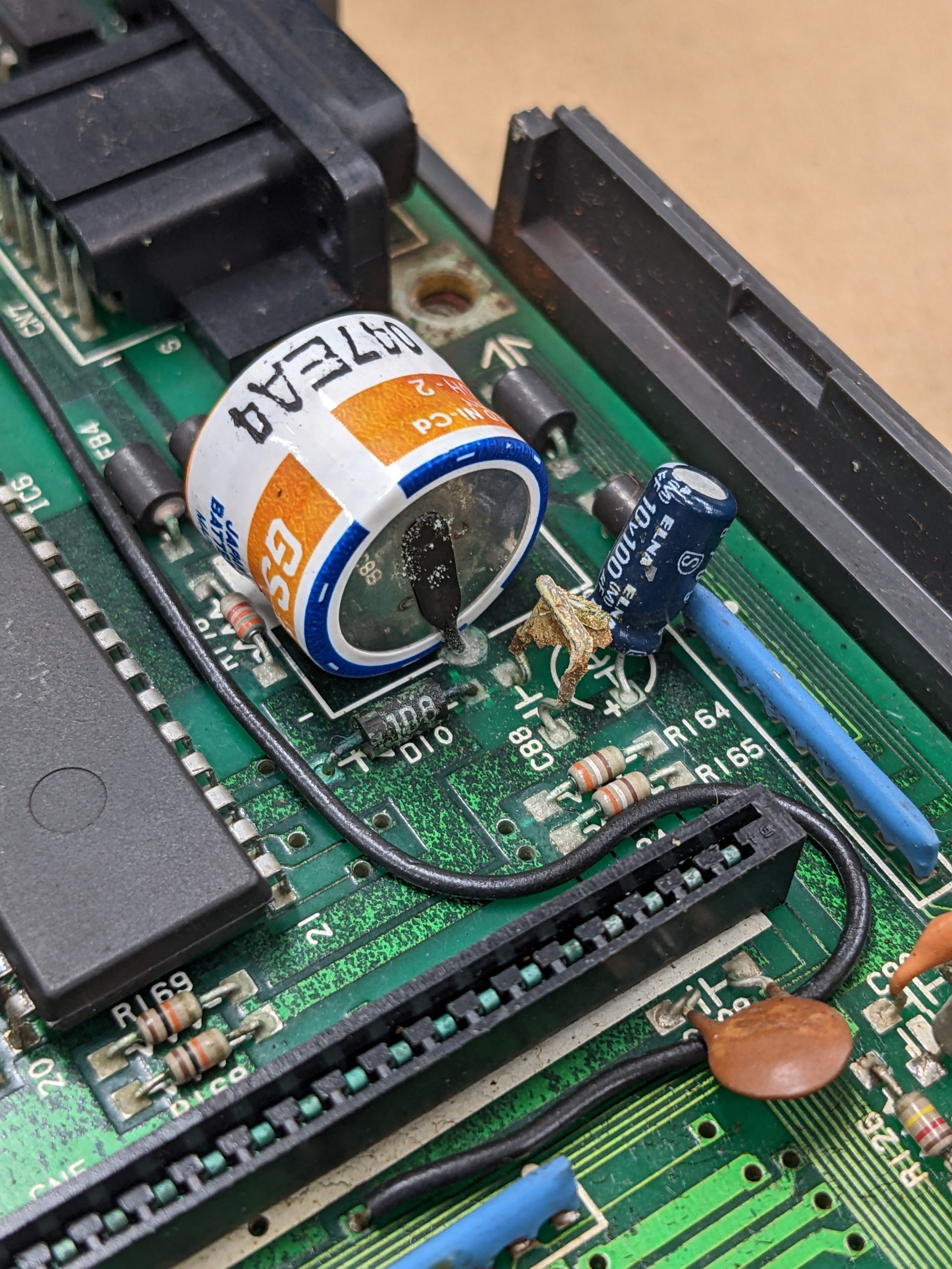
Summary: this machine contains a NiCad battery, which leaked. The machine started working after cleaning up the leak. That’s the good part. Let’s jump into the nitty-gritty.
TBH, I thought this’d be a no-fix at this point.
Some electrolyte also made its way up to the keyboard PCB. All these traces tested fine.
The first step is to remove the battery. The second step is cleanup. Fortunately, all internet sources I read stated that cadmium doesn’t leak out of the battery, just the electrolyte (maybe at ppm or ppb levels, but nothing to worry about IMO as long as you don’t use your bare skin or tongue to clean up the leak). There are various sources out there about how to best go about the cleanup. I only used IPA for now. I’m thinking of giving it a water bath… But I’m too much of a chicken. D:
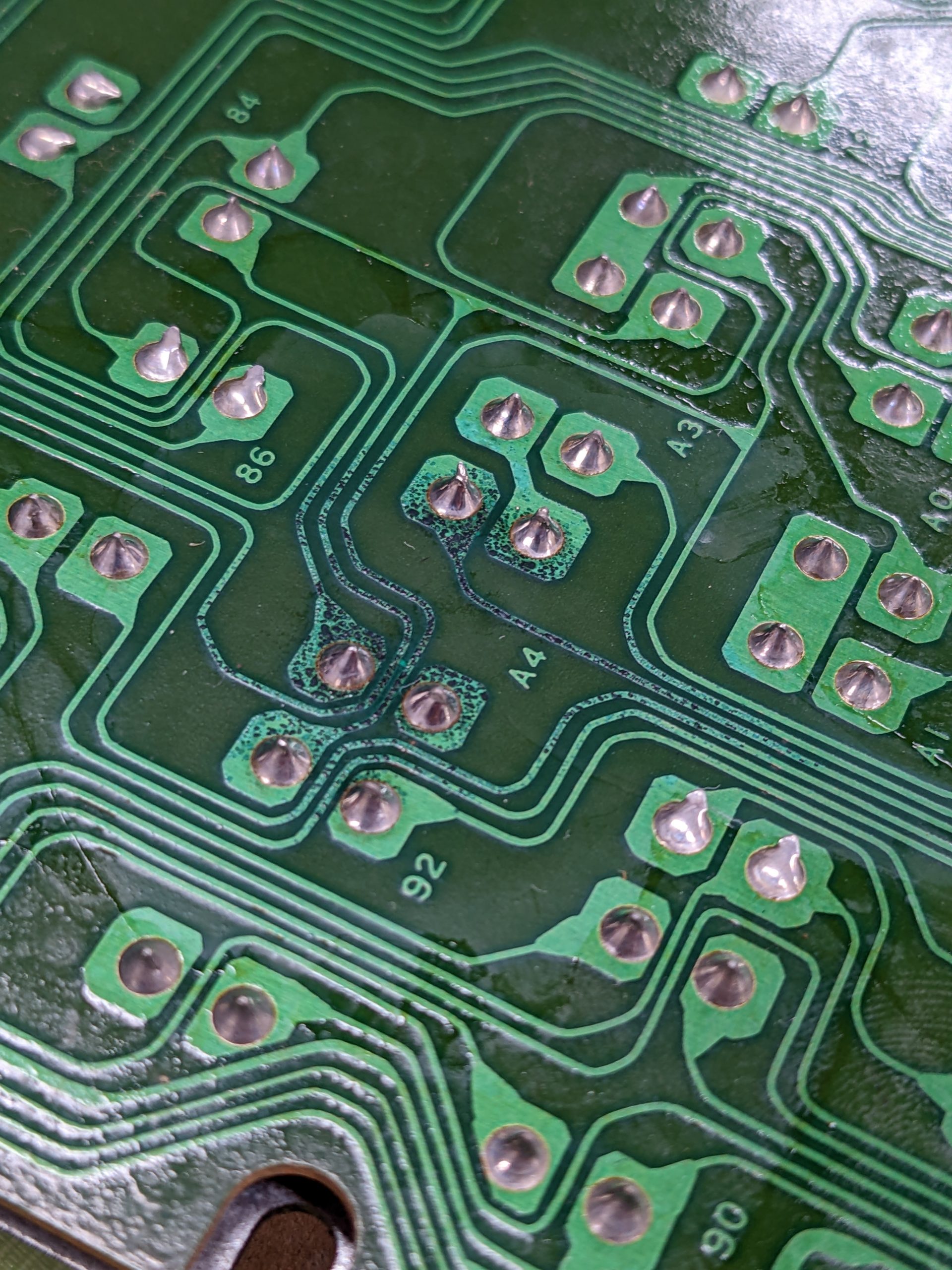
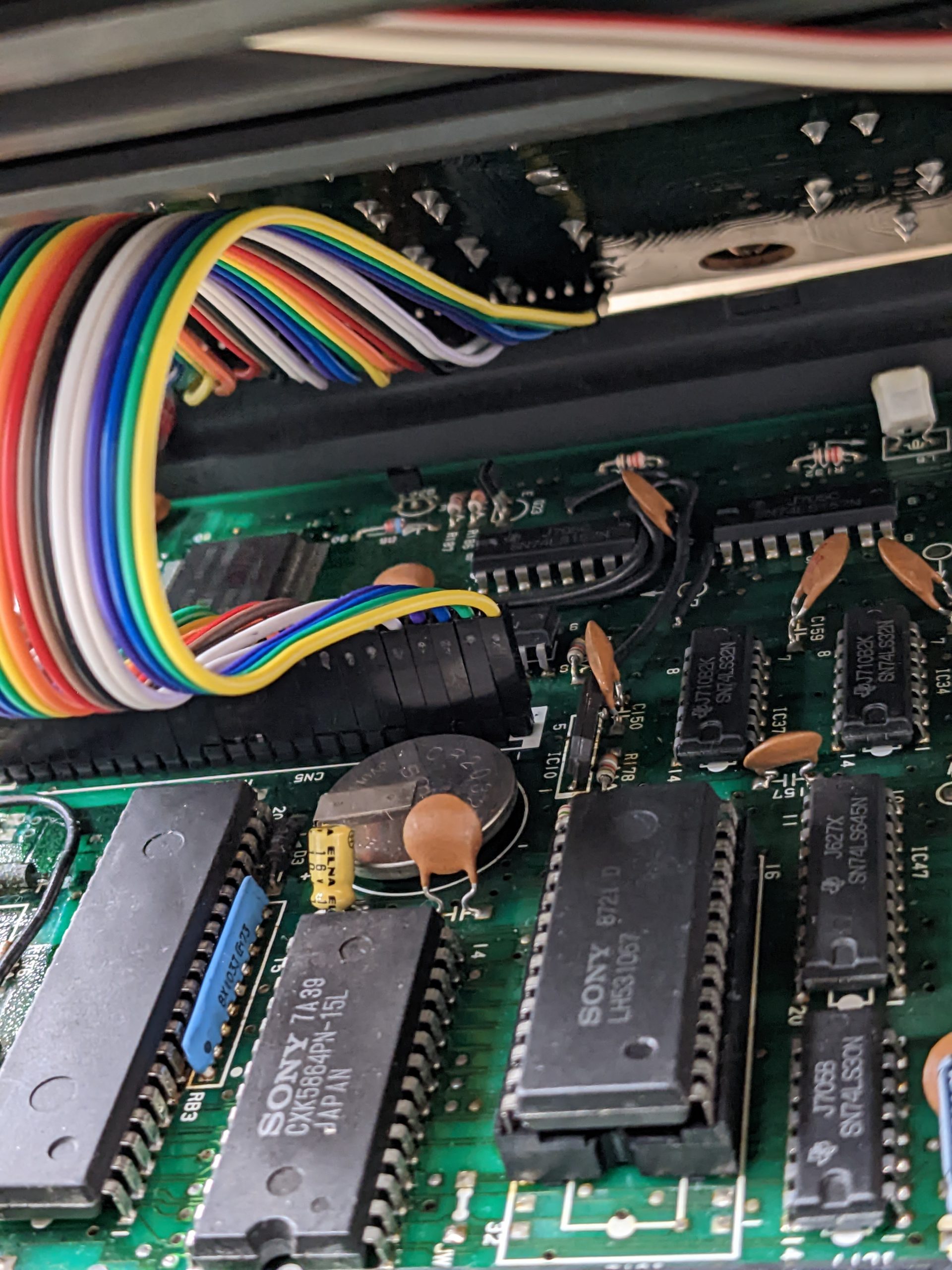
The NiCad battery destroyed a joystick trace, which prevents one of the joysticks from working correctly. (The traces to the right of the NiCad battery, right at the edge of the board, are for the upper joystick.) Unfortunately, this trace goes into a SMD chip, the Yamaha S3527. With through-hole chips, we could just add a bodge wire on the back of the board. With SMD chips, we have to repair the trace. I elected to skip doing this, as I’m not sure where the trace is broken. Judging by the visuals, it could be broken along its entire length or in multiple sections. Also, adding a long bodge wire on the top of the board seemed kind of messy. So we’ll live without one of the joysticks for now.
Edit 2022/12/04: I repaired the trace. I scraped off solder mask in various places, narrowed it down to a small region, scraped off more solder in that region, and tinned the trace. (I used my poor multimeter probes to scrape off the solder mask.) That made it a bit easier to find the exact location of the two breaks. I ended up using solder to bridge the breaks. These traces are tiny, and I also had to take out a ferrite bead to get to the right one. And of course, while soldering the ferrite bead back in, I melted the solder bridge and had to have another go at it. Though it was much easier of course as it was already mostly there. As the drop of solder could break off, or nearby rework could break the trace again, so this isn’t the best way to fix it. It would probably be best to solder in a very tiny wire.
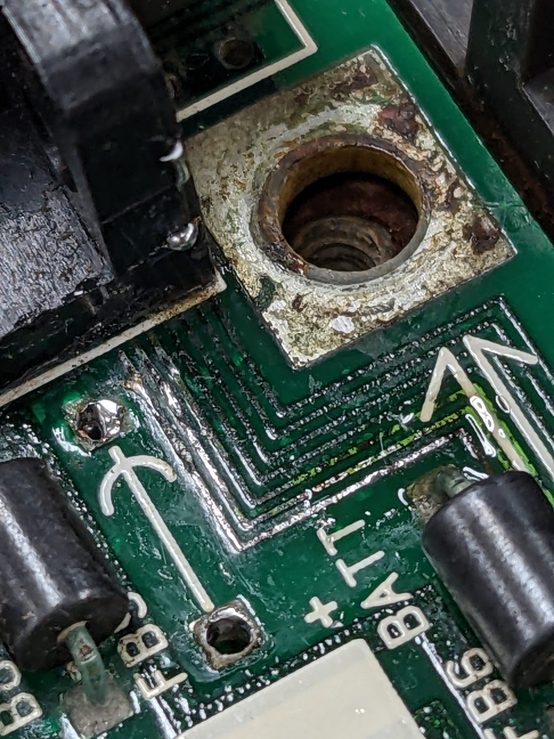
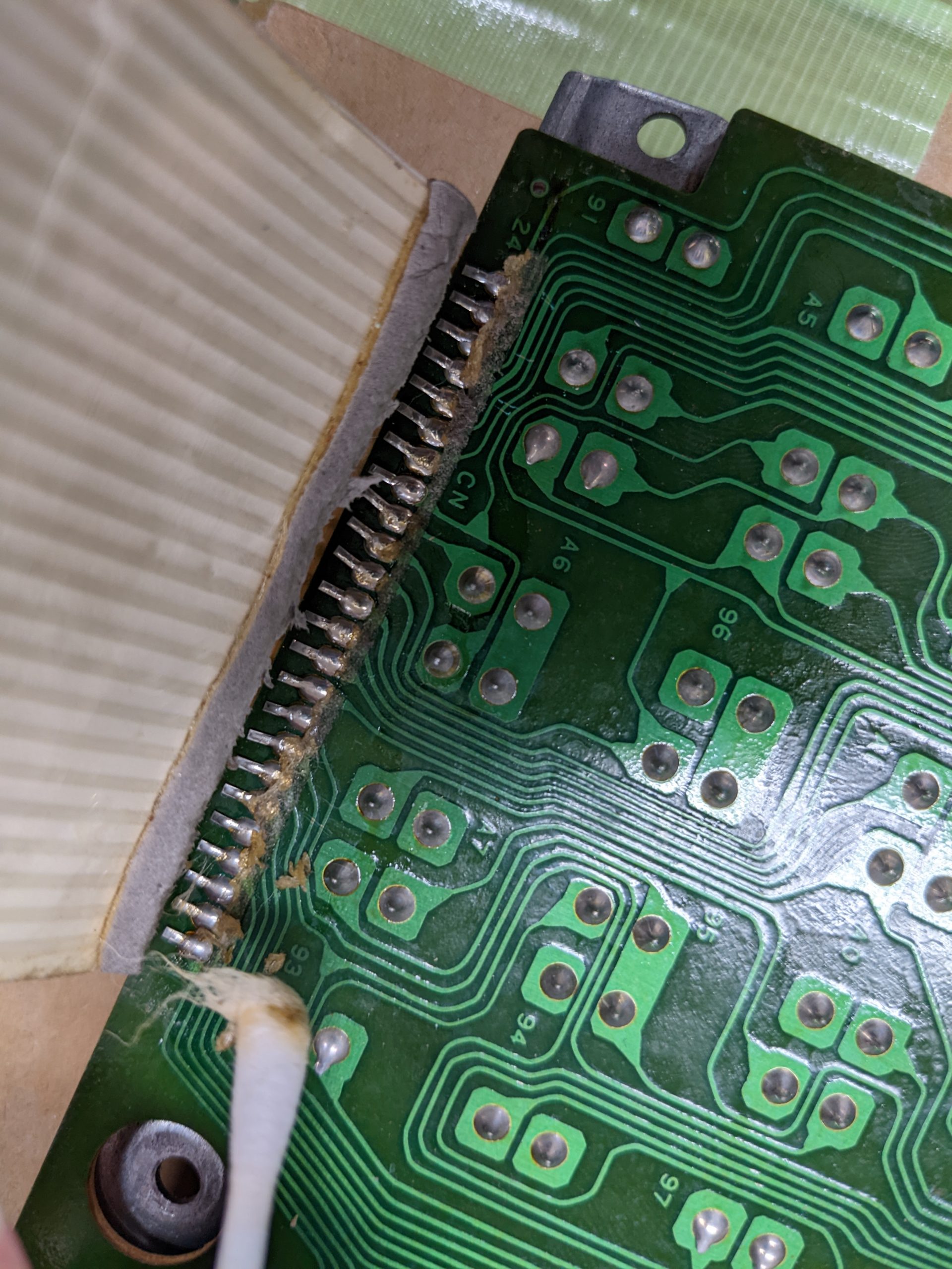
The battery leak also destroyed a capacitor (C88) and the flexible cable for the keyboard (and its connector, more or less).
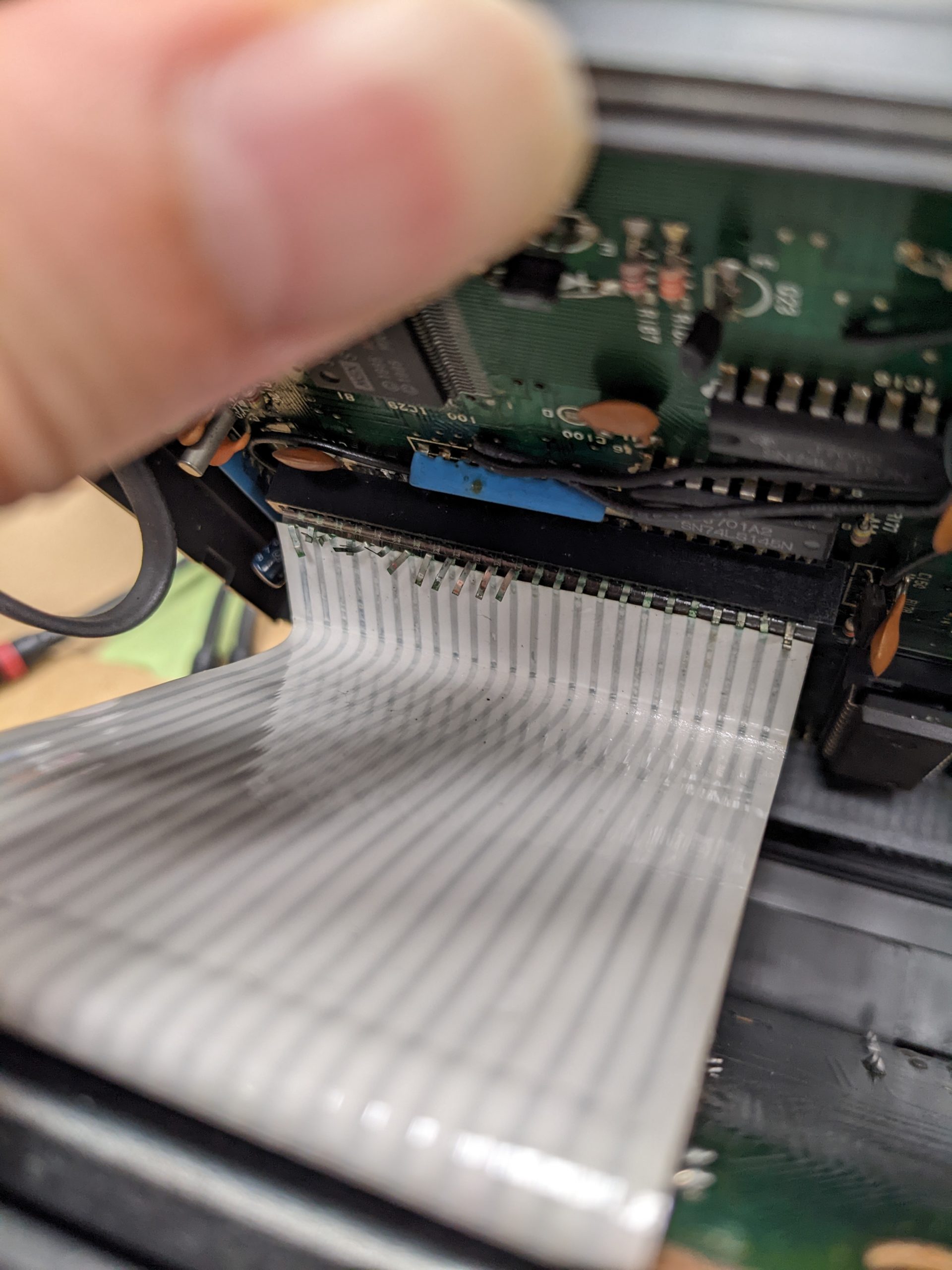
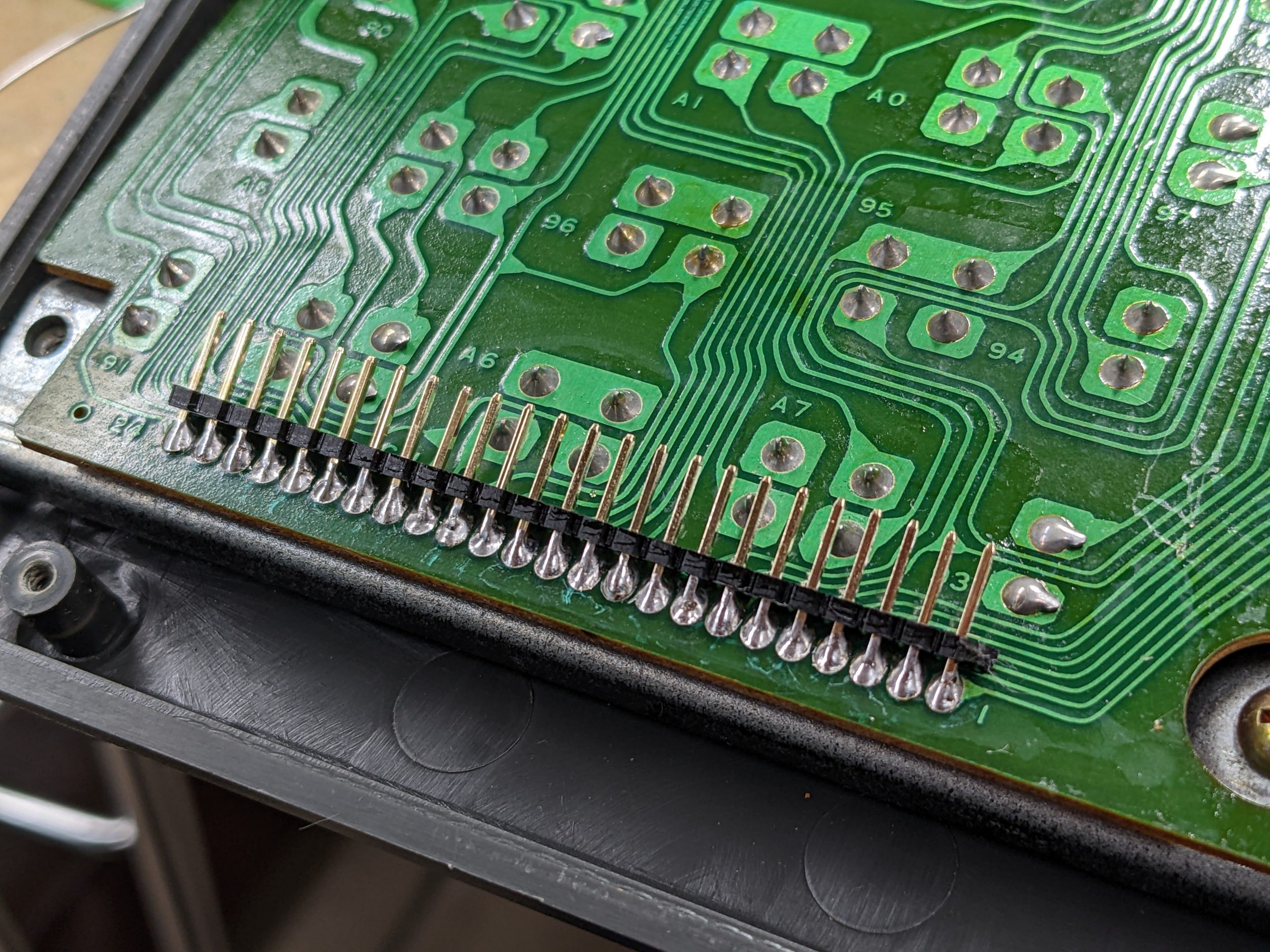
I desoldered the keyboard connectors (both on the keyboard itself and the mainboard), and added pin headers instead. Here are some pictures of the removal process:

I’d planned on just running jumper wires with DuPont connectors, but my jumper wires were too long. The keyboard worked, but I was no longer able to fit the computer’s lid on its case because the jumper wires would bump against the cartridge slot. Putting on and taking off the jumper wires one-by-one was pretty annoying, so I decided to use a ribbon cable as used for IDE drives, plus four of the jumper wires. That made it pretty easy to plug and unplug the keyboard, which is useful when switching between software-based tests and hardware fixes. However, the lid still wouldn’t fit very well. It was just barely possible to close it, but it very much relied on the screws to hold it in place.
The keyboard had a couple of non-working keys. The keyboard isn’t very “repair-friendly”. Each key switch has two little feet. When taking out the key switches, you are likely to break them off.
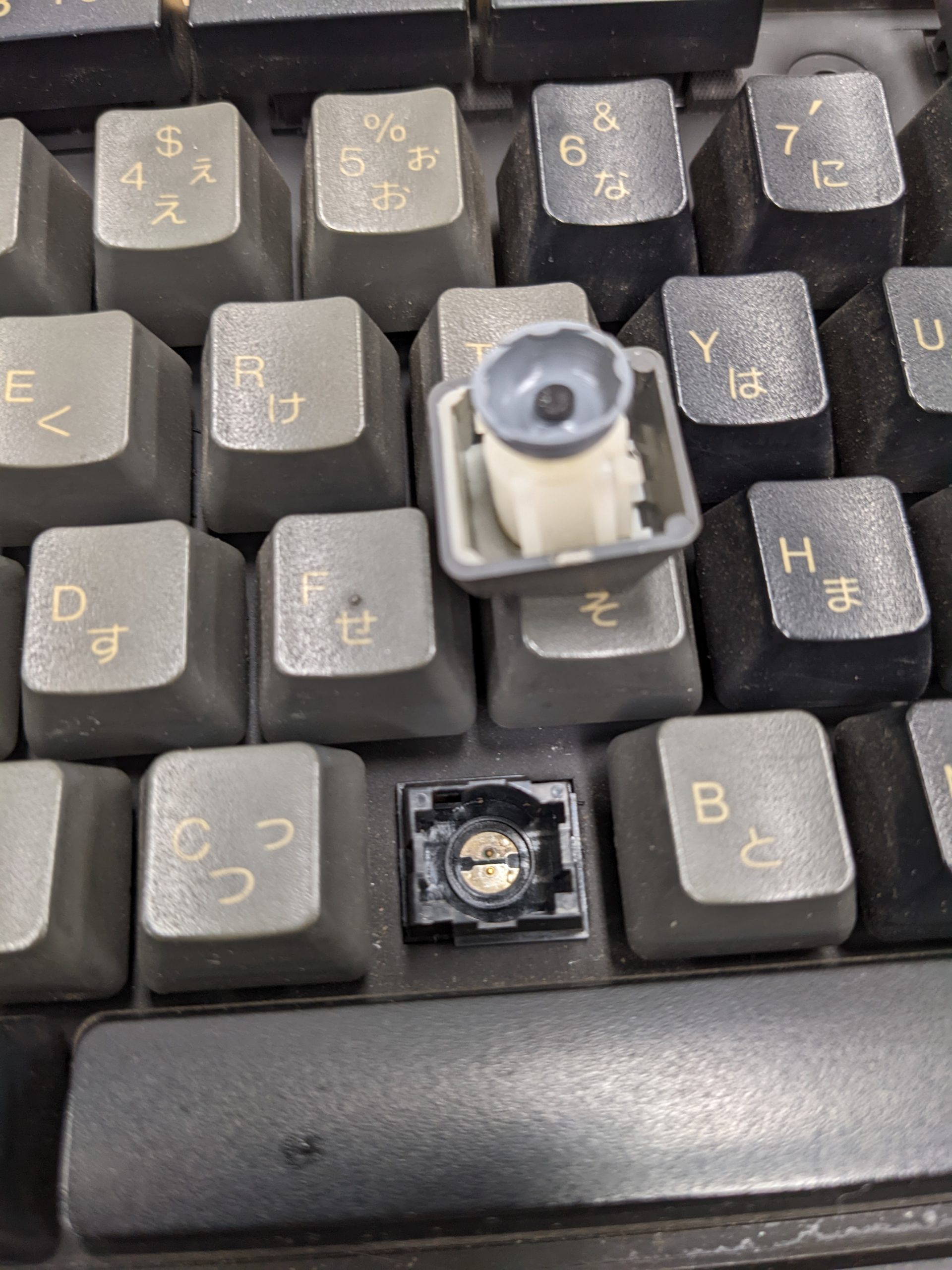

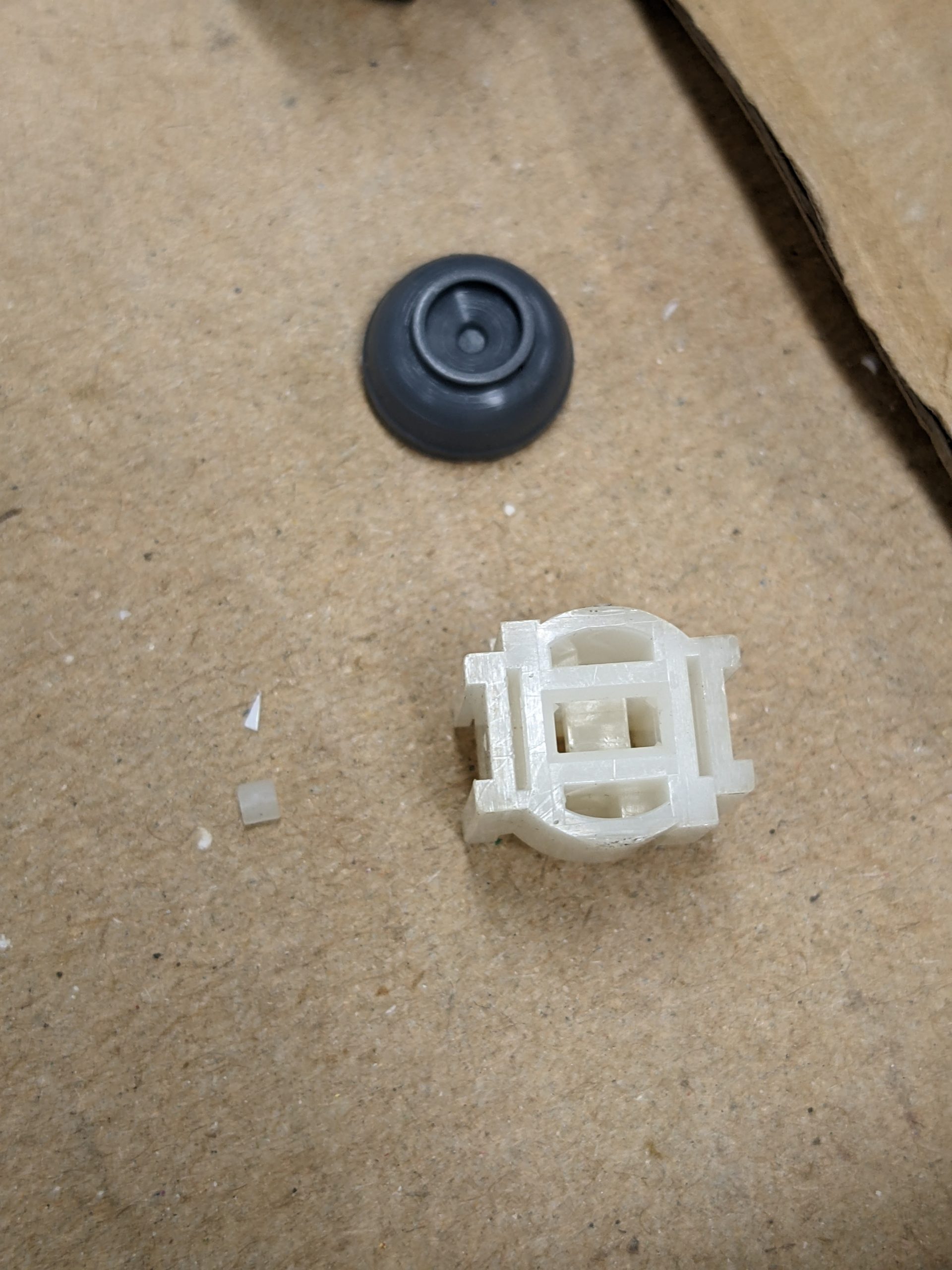
On the bright side, there are two of these clips, and one is generally enough to hold the key cap + key switch into the keyboard assembly.
I’m guessing that there is a special tool for these key switches. Or maybe you can put in a fine piece of metal (e.g., a dull needle) somehow. I don’t know. :(
HB-101
This machine just worked. The keyboard was filthy, so I cleaned the key caps using my ultrasonic cleaner. Removing the key caps was straightforward.

Some time passes…
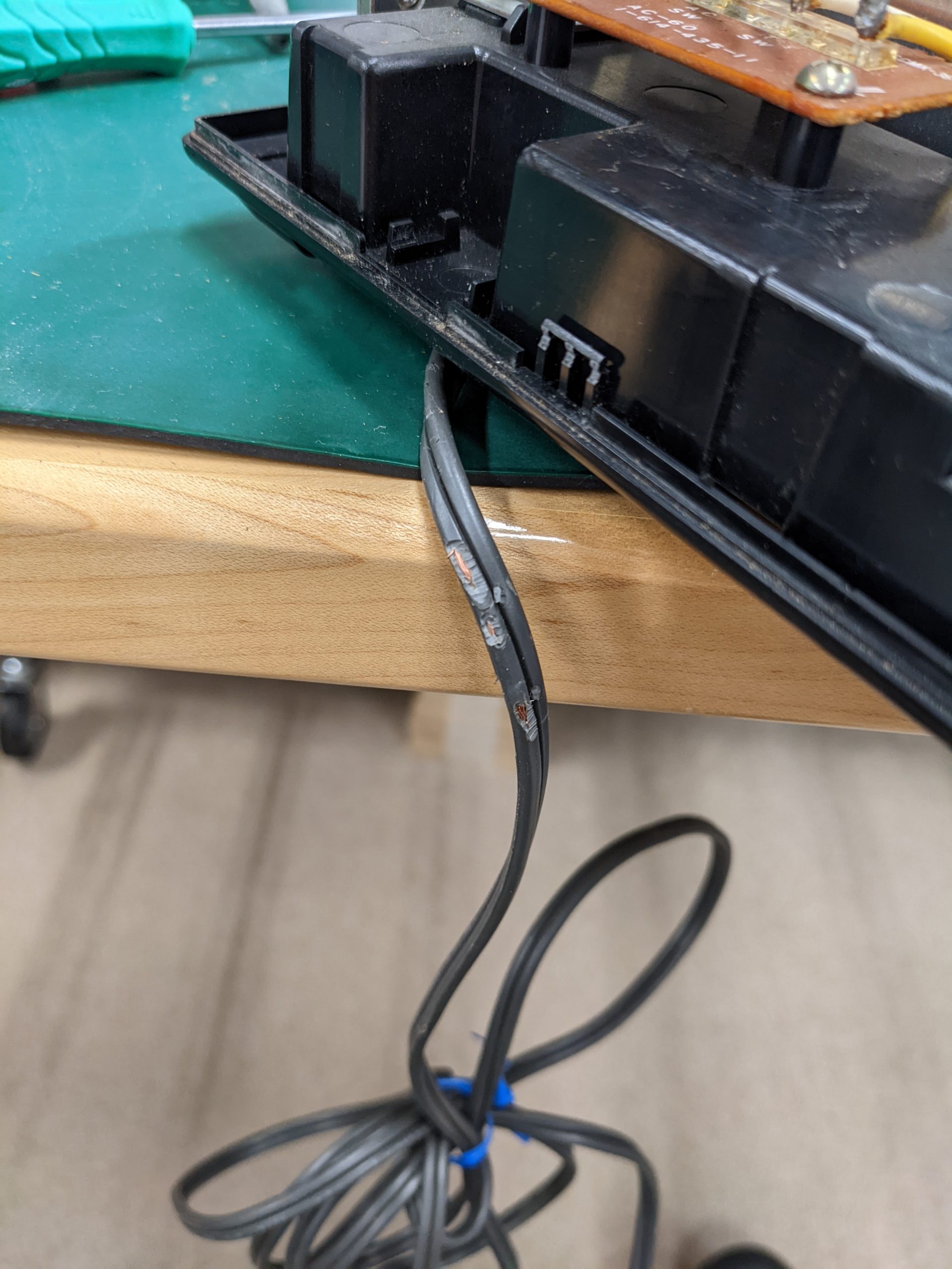
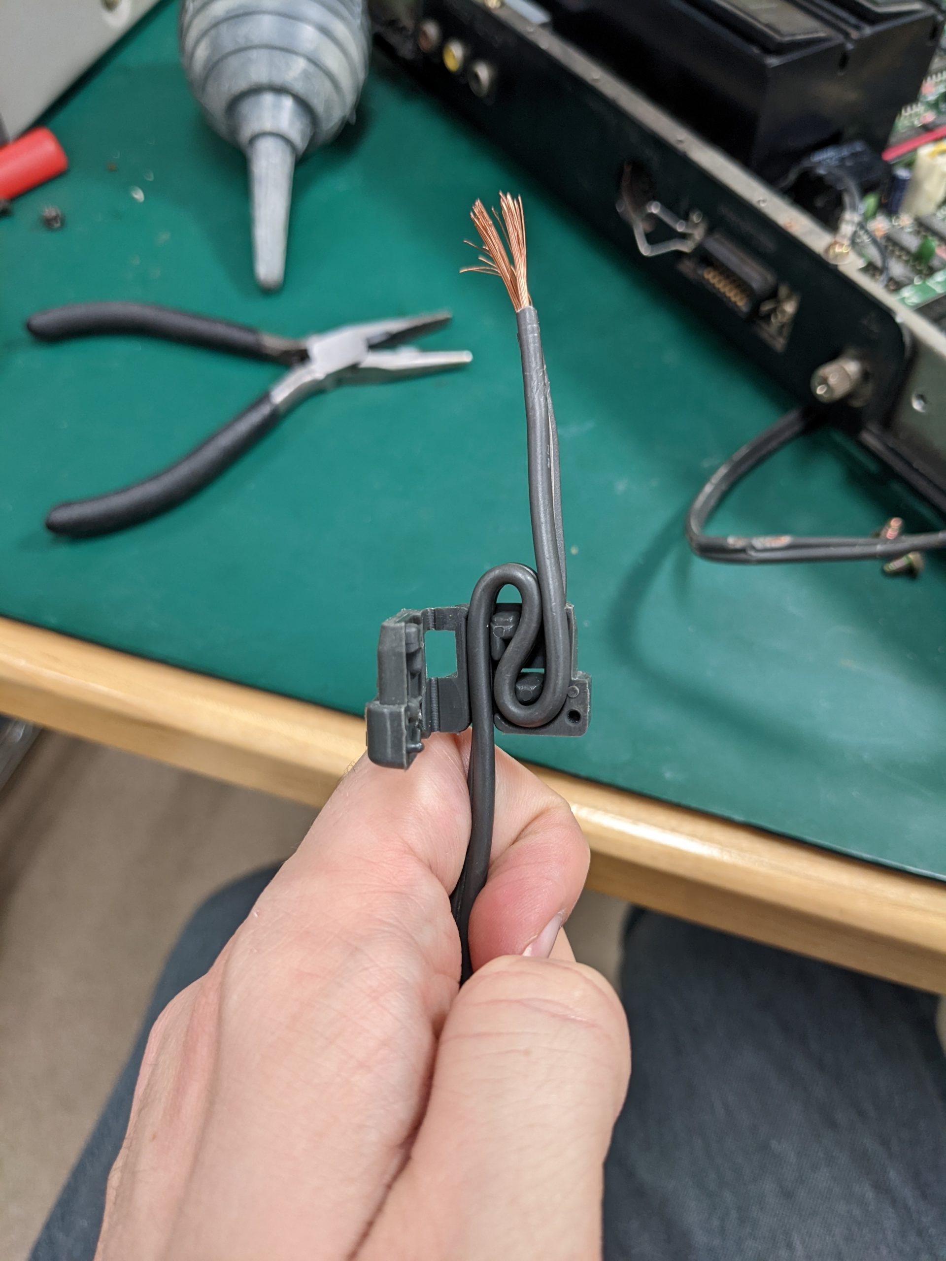
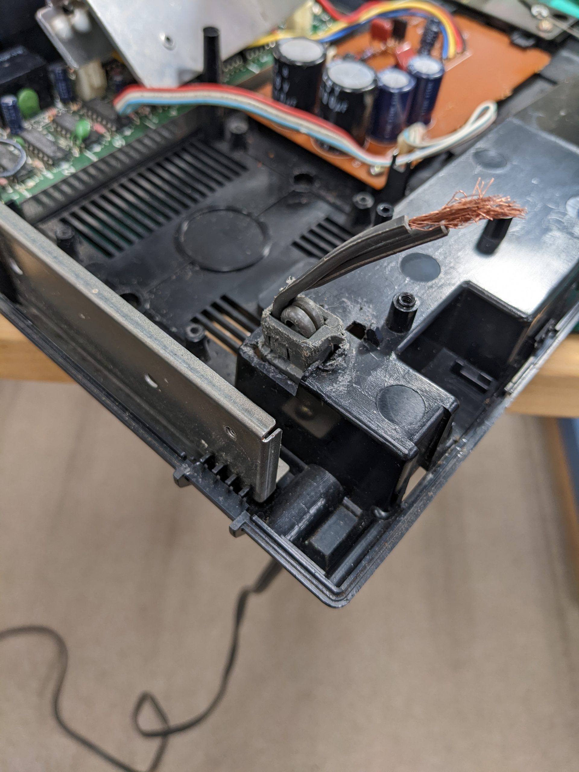
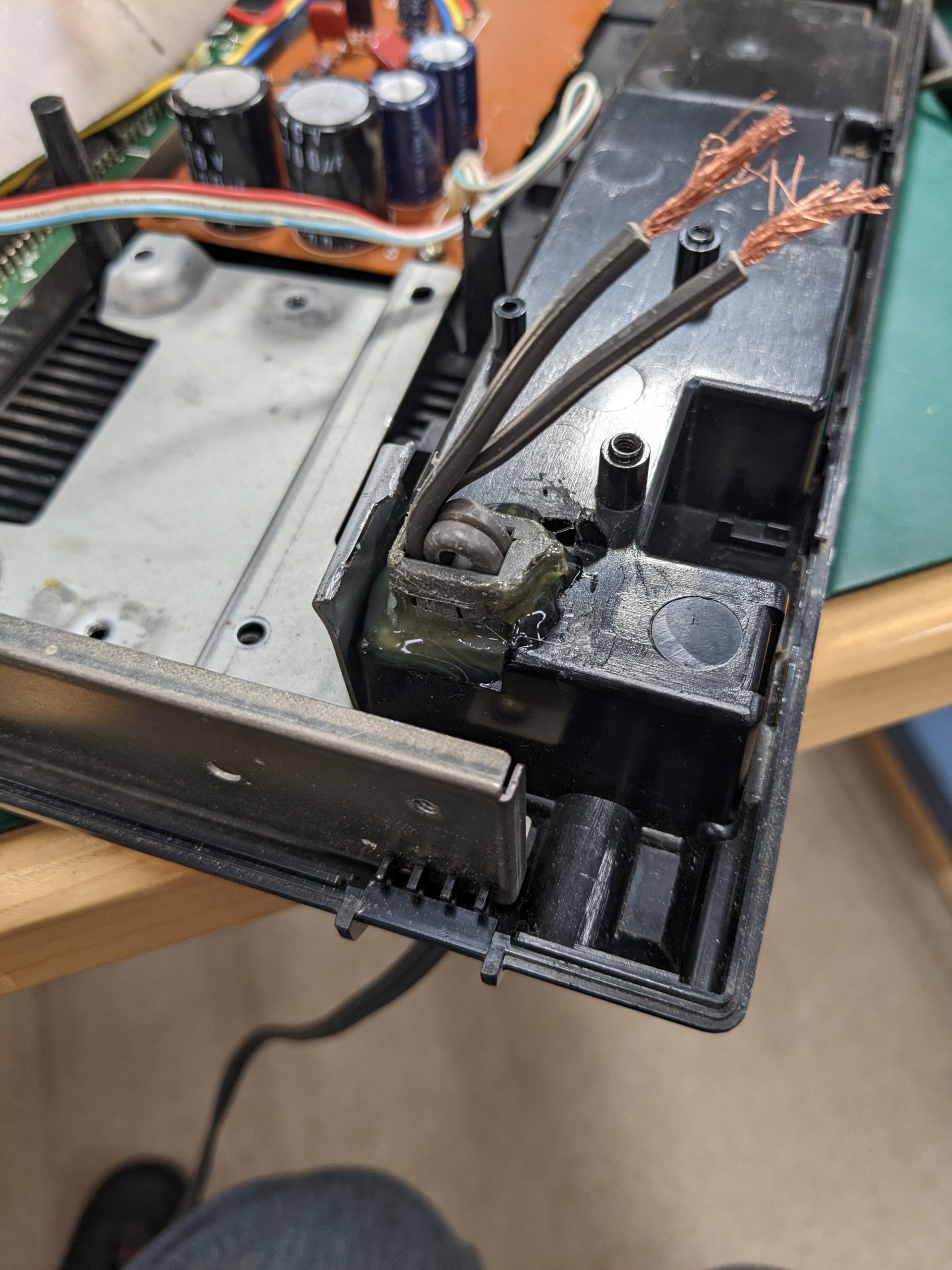
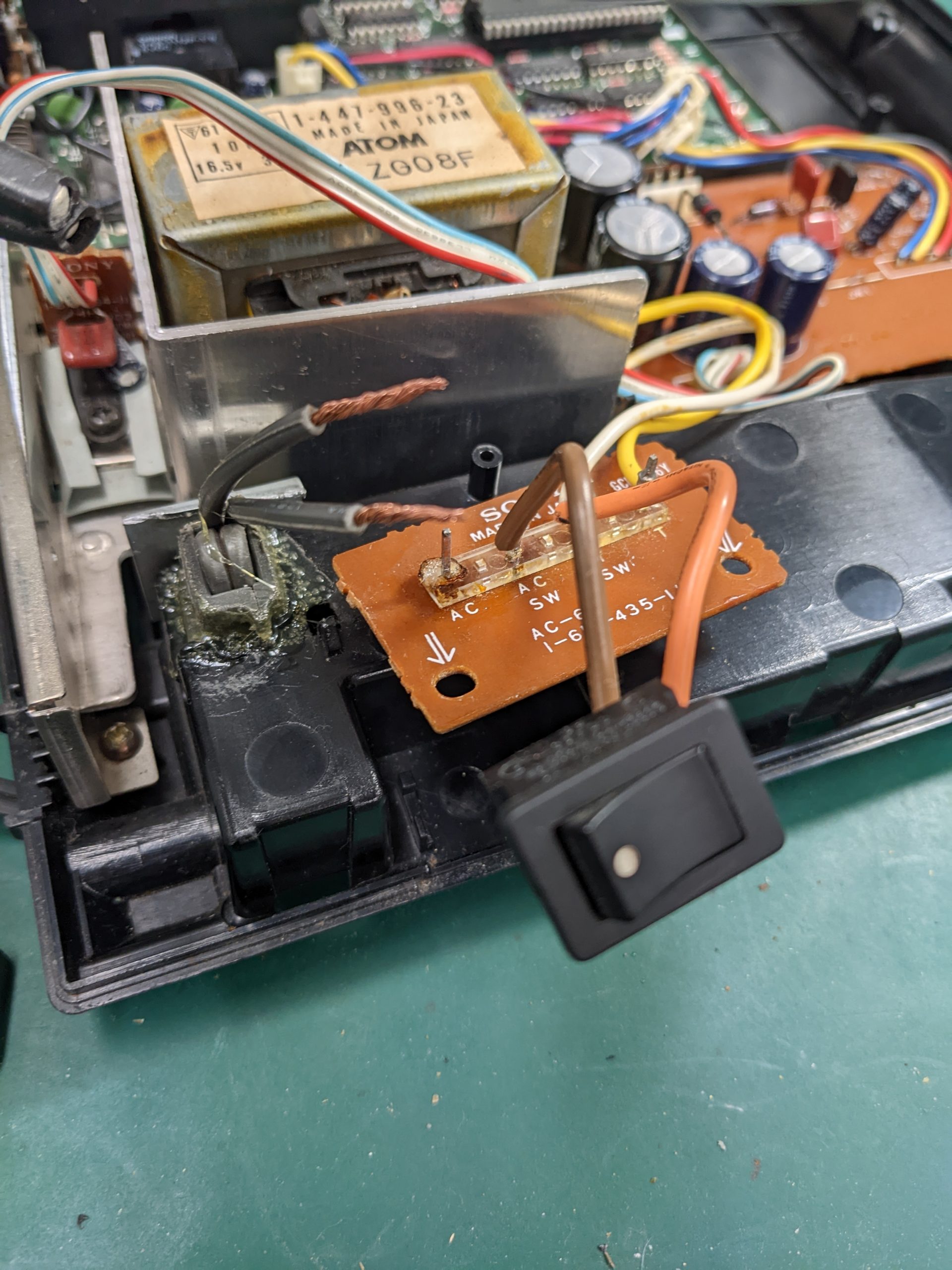
Maybe it’s a good idea to, at the very least, first of all examine the power cable before plugging in old electronics. I fixed the cable by cutting off this section, which meant I had to desolder the old section from the terminals, wire strip, and re-solder.
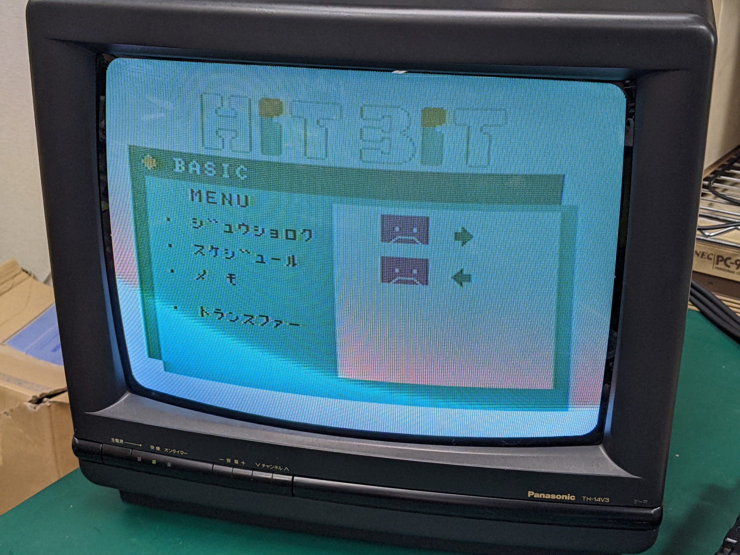
Those tape icons look like unhappy faces, which had me worried for a second.
HB-11
Just broken solder joints on the AV connector.

BTW I think audio broke again. I’ll take another look sometime soon.
Update 2022/12/03: Audio was indeed broken again. Bad solder joint on Q2’s emitter. Factory didn’t use enough solder. Hardly any solder, in fact. Fixed.
Summary
None of these repairs went off without a hitch.
HB-F900: success!
HB-10: success!
HB-T7: broken clips on key switches. Also need to put some more thought into the keyboard connection. Joystick not fixed. (The lower joystick is fine.) Update 2022/12/04: joystick traces are fixed (see above)
HB-101: needed glue. Perhaps there’s a special tool that they used at the factory for the stress relief thingy. Or perhaps they’re one-way. Not a huge problem IMO.
HB-11: audio is broken again. Sure, the connectors are probably not that great in the first place, but still… Update 2022/12/03: fixed.