In a previous article we were able to see that one of our 4164 RAM chips didn’t produce a clear 0 or a clear 1 when asked to read from its memory. In this article we’ll hunt for more broken RAM chips by comparing the output from a known good 4164 RAM chip with the output of each installed 4164 RAM chip.
Basically, we place the known good 4164 RAM chip on a breadboard next to the computer to test, and then connect all address, RAS, CAS, WRITE and D pins to the equivalent pins on one of the 4164 RAM chips on the computer (by using tiny test clips, of which you will need at least 12, but more would be better). Then, we attach one oscilloscope probe to the Q pin on the known good 4164 RAM chip and one probe on the Q pin on the RAM chip to test (we’ll test each one, one by one). (Note that D and Q pins are often shorted, so if that is the case we can also attach the probe to the D pin on the RAM chip under test.)
We should then hold down the computer’s reset button and (while doing so) set the oscilloscope to trigger on a positive edge from the known good RAM chip’s Q pin, zoom out so we can capture a good amount of activity, and then release the reset button. We expect both chip’s outputs to be exactly the same. If there is a discrepancy, either the connections are bad, or we have found a broken RAM chip. (Be sure to check your connections using your multimeter’s continuity mode, and try hard not to touch the cables while probing around.)
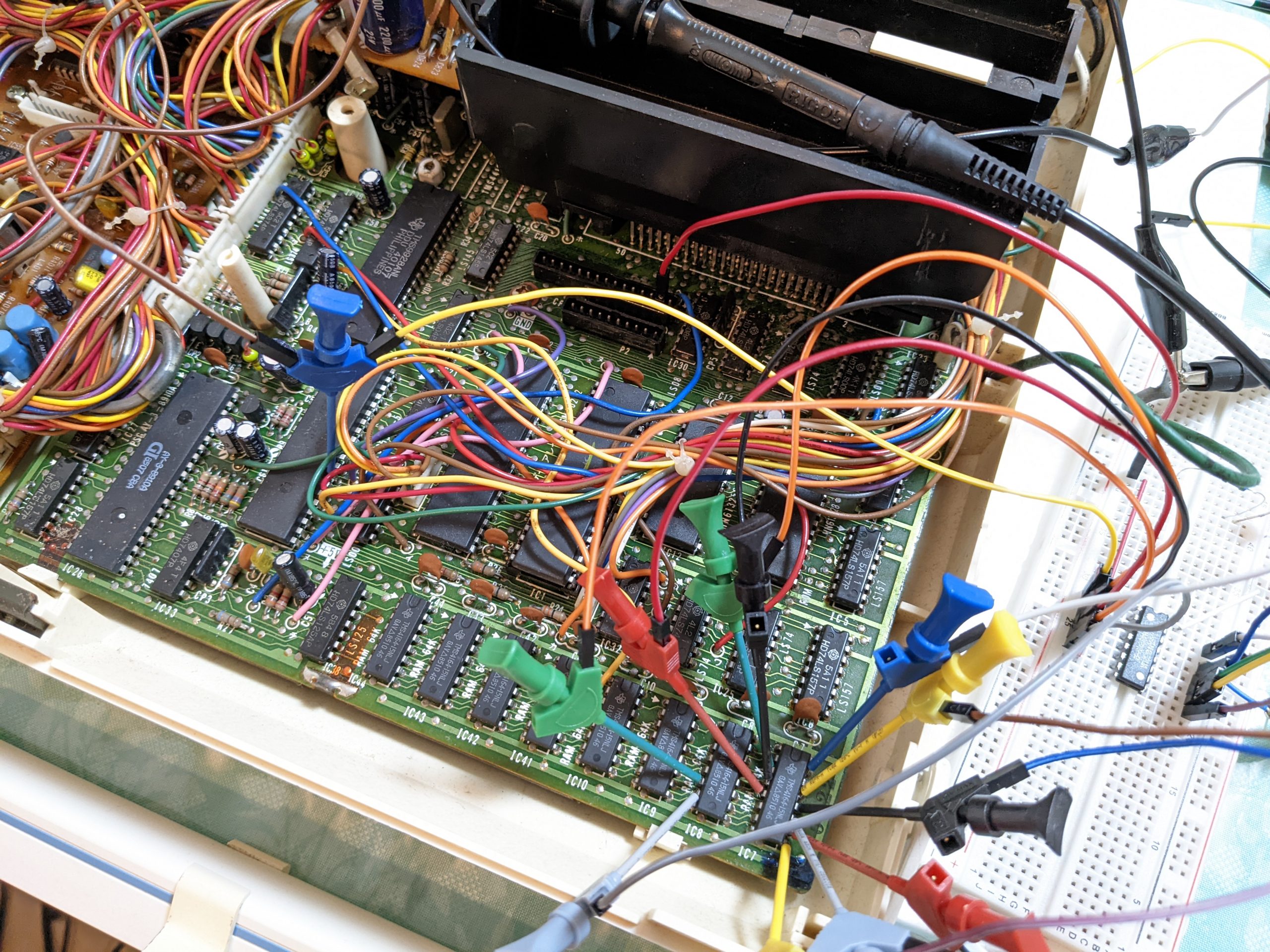
Here’s a picture of my setup:
If your testing shows that the RAM chips under test never produce the same signal as the reference known-good chip, then your wiring may be messed up. If on the other hand the signals always match up perfectly, then it seems likely that none of your RAM chips are bad. Finally, if there is a single RAM chip that often (but perhaps not always) produces a late signal or a different signal, you may have found a bad RAM chip.
In my case, most chips seemed to produce consistent signals. However, touching the cables often messed up signal integrity and I had to re-measure multiple times. I believe that the RAM chip for D7 was bad, as it often produced late or wrong signals even though the connections should have been stable.
In the below video I’m scrolling along an oscilloscope capture. You can see that when the yellow line (which measures the output of the reference chip) goes high or low, the blue line also goes to (or stays at) the same level. This means that we’re getting the same output on both, which is good.
(There is a lot of other activity on the blue line, which we don’t know much about — some of it’ll be I/O to other chips, some will be writes to the RAM. The only thing we have that we can compare to is the Q output on the reference chip, so all we can do is check whether the transitions from 0 to 1 and from 1 to 0 on the output of the chip under test are correct. We are not able to check 1 to 1 or 0 to 0 outputs.)
For the less video-inclined readers, here is a screengrab showing a correct signal:
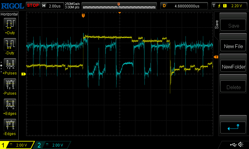
We have two transitions in the above screenshot. The first transition looks confusing at first because the blue signal takes a nosedive right after the yellow reference signal goes up — but that’s not too important, what matters is that they both have the same level for a short while. The blue line was already at “high” due to other I/O. (Also ignore the fact that the yellow line goes slightly higher than the blue one.) In the second transition we have a very neat and synchronized nosedive on both lines.
Here is a screengrab showing an erroneous signal:

Here we have two transitions on the yellow channel, and both times the blue channel goes to the exact opposite logic level. This isn’t perfect proof of a bad RAM chip — first of all we should make sure that this is repeatable and not due to wobbly probes. Second there is a slight possibility that some other device thinks it’s its turn to play with the bus (but normally that would show up as a voltage level somewhere between 0V and 5V).