I’ve been developing software for the ESP32 and ESP32S3 “professionally” for about one year now. I still like the Raspberry Pi Pico better, but the ESP32 line of microcontrollers is cool too. And if you need wireless and don’t really care too much about power consumption, the ESP32 (or -S3 or what have you) is a nice thing to have around.
The examples in IDF (the name of the ESP32 SDK) are really great, and you can do a bunch of stuff just by taking an example and changing a couple lines.
I’m a huge fan of the Raspberry Pi Pico’s PIO, and the ESP32 has something that is slightly similar, as-in “programmable IO”. It’s called “RMT”, and in examples/peripherals/rmt, we have a few examples that make use of this bit of silicon. The examples/peripherals/rmt/ir_nec_transceiver example is the one we look at in this article.
Basically, all you have to do is flash this to your dev board and connect an IR receiver module’s output pin to GPIO19 (and its VCC and GND to VCC and GND. Be sure to hook it up to 3.3V, not 5V.) If you want to do what this example is supposed to do (output the same signal back through an infrared LED on GPIO18), feel free. But if you just want to sniff codes, leave the infrared LED disconnected and look at the UART output.
Note that the output of the IR receiver is expected to be inverted compared to the actually sent signal. I think most IR receivers invert the signal, so you’ll most likely be fine.
Build steps
If your dev board isn’t a standard ESP32, but e.g. an ESP32S3, you first have to do:
idf.py set-target esp32s3
Then you do:
idf.py flash monitor
This will build the example, flash it to the dev board, and start a monitor.
Then you’ll see a bunch of output like this:
NEC frame start---
{0:218},{1:0}
---NEC frame end: Unknown NEC frame
But if you press a key on a remote control, you may see something like this:
And there you have the address and the command! Note that by default, extended NEC codes are allowed. (However, the remote control I used here generates a non-extended NEC code, where the second byte in the address (and command) is the first byte but inverted. I.e., 0xFF == ^0x00, 0xCE == ^0x31.)
And that’s all! If you output this using an IR LED (make sure you use a resistor), you will be able to control the device in question using your microcontroller. Note that you will probably have to move the LED rather close to the device you’re trying to control (depending on your resistor value). Note that you shouldn’t really exceed 30 mA per GPIO. I understand that most IR LEDs are good up to 100 mA, but the ESP32’s GPIO pins aren’t. You’ll need to amplify the signal if you want to go higher than 30 mA.
Sniffing IR (NEC) codes on the Raspberry Pi Pico
The Pico has a very similar demo, pico-examples/pio/ir_nec/ir_loopback/ir_loopback.c. If all you want to do is sniffing, it may work a little nicer if you comment out the sending stuff (everything from “// create a 32-bit frame and add it to the transmit FIFO” to “sleep_ms(100);”), as well as the sleep_ms(900) at the bottom. (Otherwise you’ll have to wait a little bit until your IR code shows up.) Also, it won’t do extended NEC codes. You’d have to modify nec_receive.c a little bit.
A while ago, I watched a series of videos by DrMattRegan on the ZX80 and was very impressed with the uber-hacks the designers put in there. I’m not going to go into much detail here, but here is a set of facts that may pique your interest:
The CPU’s A6 pin is permanently shorted to its \INT pin
The ZX80 has only 1 KB of RAM
The RAM is SRAM but the CPU’s internal DRAM refresh counter is not wasted
Additionally, the ZX81 was one of the first retro computers I ever repaired (article 1, article 2), which made the prospects of getting a ZX80 of my own even more attractive to me.
You have a lot of options if you want to build a ZX80 yourself. First of all, all the ICs (except the 2114 SRAM) can be bought new. There are multiple PCB designs that you can download for free, some electrically equivalent, some using chips that are a little more common than the ones on the original PCB. (For example, apart from the 2114 RAM, the 74LS93 is pretty rare because it is essentially useless nowadays. It was probably cheaper than the other 74-series counter ICs about 50 years ago, because a lot of “maybe nice to have” features were removed. It can easily be replaced using a different 74-series counter IC, and these days there really is no price difference.)
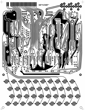
One thing that I really liked about the ZX81 that I worked on was the curved traces and the absence of solder mask on the traces. On this page by Grant Searle, you can find instructions to re-create the original PCB. There is a PDF that contains high-res images that look like this:
These can be printed out and turned into PCBs. I’m not much of a chemist, and even if the etching and tinning processes went well, I’d still need to do a bunch of drilling and then plate the newly drilled vias. Nowadays, there are companies such as PCBWay and JLCPCB that can do all this for you, and in an automated fashion, and for very attractive prices! (I do not intend to steer you away from etching PCBs yourself, in fact it always impresses me when people make PCBs themselves!)
However, these companies (currently?) do not accept bitmaps (as far as I know), they want Gerber files. So I traced the (600 dpi) bitmaps in Grant Searle’s PDF file and sent them out. I chose JLCPCB after some research because I found a pic of a board manufactured by JLCPCB that didn’t have any solder mask applied, and it looked pretty much the way I wanted it! However, I’m sure that PCBWay could do the same.
In order to get a board without solder mask, you have to get rid of the solder mask layer in the SVG or Gerber file, and you probably should also add a comment stating that this is intentional. I added this in my order, no guarantees the Chinese is correct: “The Gerber files don’t have a solder mask. This is intentional. Please do not apply a solder mask. Gerber文件没有焊膜。这是有意的。请不要应用焊膜。 我们有会说中文的人,所以如果你有什么问题,可以说中文。” I ordered 5 boards (which is the minimum order), lead-free HASL, white silkscreen (“ink-jet/screen printing silkscreen”), no gold fingers (not present on the original PCB either), regular PCB thickness (1.6 mm), regular outer copper weight (1 oz), regular via covering (tented), no castellated holes. JLCPCB’s customer service recommended I switch to ENIG, but it worked out fine with regular lead-free HASL. The price was $18.02 plus $11.70 shipping, minus the first time discount ($5).
When exporting the Gerber files in KiCad, you should follow the PCB manufacturer’s recommended settings. JLCPCB and probably most other places have a support page for this, this is JLCPCB’s.
A glimpse of the outcome
Tracing bitmapped PCB foils
I used Inkscape to trace the PCBs in the PDF. Tracing is easy, you just load a bitmap and then go to “Path” -> “Trace Bitmap…”. But how do you convert that into Gerber files? Well, there is an extension that converts SVG files to KiCad files, svg2shenzhen.
It still took me many, many hours though. Why?
Converting traced holes to actual drill holes
svg2shenzhen expects “circle” shapes in a layer called “Drill”. If that layer doesn’t exist and/or it doesn’t contain circles, there won’t be any drill holes in your Gerber file. I wrote a very simple Inkscape extension to do this: Converting paths to circles in Inkscape
But first, we need to separate out the holes into a single layer. To do this, we first break apart the path containing all the traces (“Path” -> “Break Apart”). Then everything that isn’t connected together, and everything overlapping other things will exist as separate paths. Holes overlap other things and thus will be separate paths. And they will be obscured by the outer path. Now you just click on the surrounding path and remove it, perhaps like this:
One more consideration is hole size. Though the details are a little hazy now, selecting multiple circles and changing their size all at once didn’t work very well for me in Inkscape, so I just edited the SVG file directly.
The traced circles are paths that more or less look like circles, sure. But they’re often slightly oval or otherwise unshapely and not all the same size. So when you (after using the extension) crack open the SVG in a text editor, you may see that the radii are slightly different everywhere:
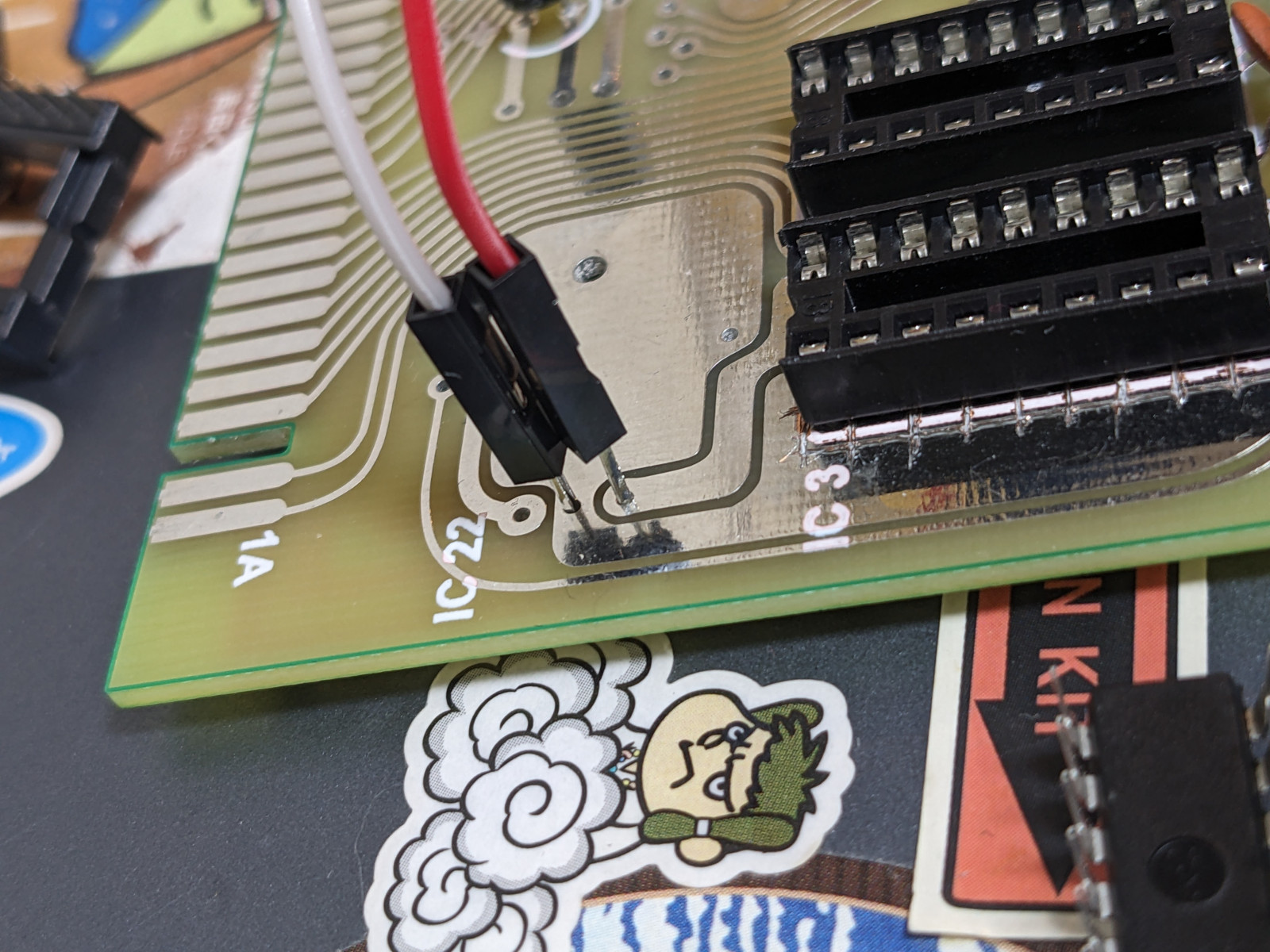
I just did a find and replace operation here and used holes sizes that seemed good to me (after JLCPCB support telling me that my holes were rather small). And damn, by sheer dumb luck, I chose the best hole sizes ever (0.4 mm) and my jumper wires fit right into them without using clips; they make almost perfect contact. Maybe 0.375 mm or so would have been even better? (The other hole sizes I chose were 0.8 mm and 1 mm.) (Note: PCB manufacturers don’t have every drill bit in the universe, so 0.4 mm and 0.375 mm may just end up being the same drill bit.)
Excellent hole size.
Update 2024-04-19: the holes for the headphone/microphone/power connectors are too tight though. :(
Adhering to minimum spacing constraints
PCB manufacturers require that certain spacing constraints are observed. For example, traces may need to be 0.125 mm apart. The original bitmap you have may or may not adhere to the spacing constraints. I don’t know whether the bitmap in the PDF adheres to them! But I certainly do know that my order was rejected because the traces in my Gerber file weren’t quite up to snuff.
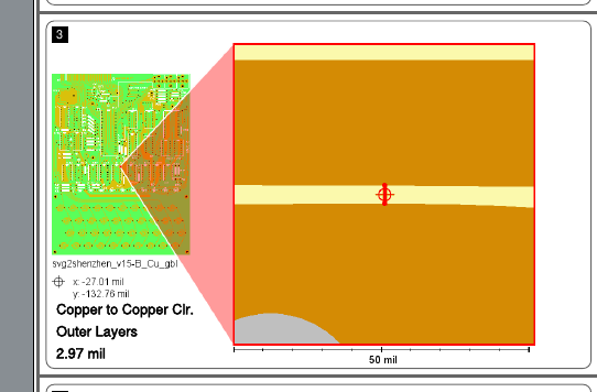
How would I even find out what my minimum spacing is? Well, I found this page by yet another company that makes PCBs: https://instantdfm.bayareacircuits.com/. This page analyzes your Gerber file and sends you a snazzy PDF with close-ups of your horrible transgressions. This is a screenshot from an early version of my Gerber files:
2.97 mil… that’s 0.075438 mm. Less than 0.125 mm!
So I manually fixed this location and re-submitted, and sure enough, there were plenty of other similar narrow gaps. So I decided there must be a way to get Inkscape to find these critical regions, and this is what I came up with:
I just gave every object a 0.125/2 mm = 0.0625 mm border, and then zoomed in a bunch to look for objects that were touching each other. (Actually I probably added some to that value, but a couple months have passed and I don’t remember.)
Border color is set to red here. Lots of… intimate traces!
Mistakes
As mentioned earlier, in Inkscape, when you break apart a path that contains “holes”, you’ll end up with a large mass obscuring the holes. Here’s a video of exactly that:
Look at the large black regions with holes, especially near the top left. The holes will “disappear” (they will be obscured) after breaking apart the path.
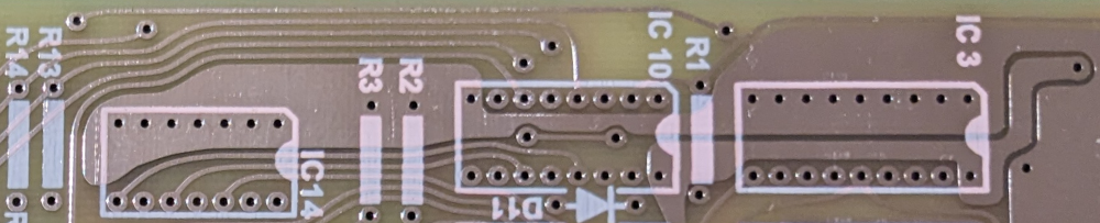
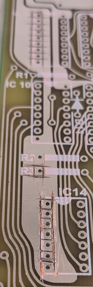
Well, I failed to notice that a number of holes within these black regions had been obscured. And thus they came out like this on the PCB:
IC3 and IC14 have their left pins all sewn together. There were a couple similar spots elsewhere, but you get the idea.
While annoying, I was able to fix this using a utility knife. Boy, that utility knife’s blades went dull quick. (Luckily, my utility knife is one where you can just snap off consumed blade chunks. Having done this for the first time in my life, it was quite scary, to be honest. I did it behind a glass window.)
Very beautiful, I know. However, once you have soldered the IC sockets, all this is mostly hidden underneath the sockets.
Procurement and assembly
After taking care of these mishaps, it was time to do a bunch of other stuff, such as celebrating Christmas and the New Year, and at some point bite the bullet and solder sockets and resistors and capacitors. I soldered everything using lead-free solder, and most or maybe even all of the components I put on the PCB are lead-free too, including the Z80! So maybe this is the first RoHS-compatible ZX81?! (Except the 2114 SRAM chips most likely aren’t RoHS-compatible. We’ll talk about those in a later section, BTW.)
I had half of the 74-series logic chips in stock. (From when I got Ben Eater’s DIY 8-bit computer, which I never assembled. I used the breadboards and some of the other components for a host of other things though!) The other half came from a small electronics shop right next to my office in Machida, サトー電気. I wanted a RoHS Z80 (print on chip ends in -PEG rather than -PEC), and bought it off Amazon.
Update 2024-04-19: Zilog/Littelfuse are reportedly discontinuing the original Z80 CPUs after almost 50 years of production! Maybe get them while they’re still available. Only source so far: https://www.mouser.com/PCN/Littelfuse_PCN_Z84C00.pdf (zilog.com still seems to list everything as “active” at the time of this writing)
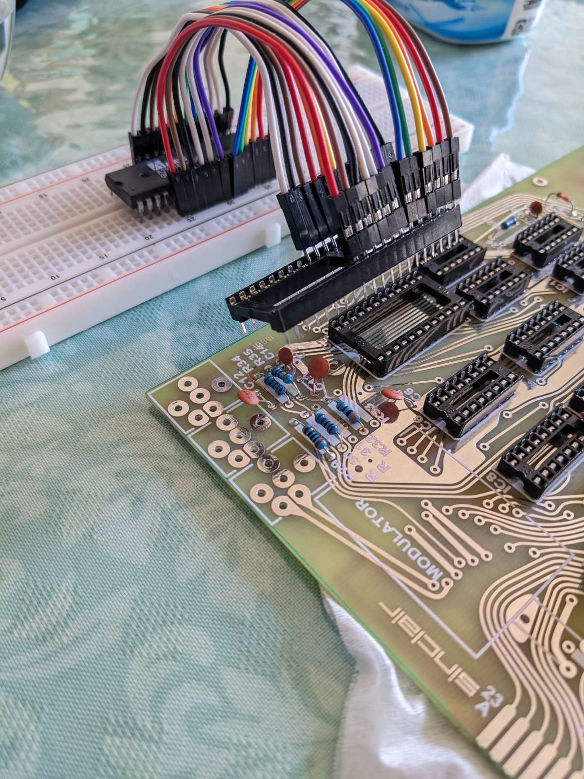
For the ROM I’m just using my EEPROM that I’ve been using in other projects. Since it’s huge and has a slightly different pinout, I’m currently using a breadboard as an adapter.
Putting jumper wires in IC sockets permanently damages the sockets. Here I am plugging the jumper wires into a sacrificial socket that I plug into the soldered socket. This way the soldered socket doesn’t get damaged.
The only thing I couldn’t get anywhere, including Akihabara, is the 6.5 MHz oscillator. Many people use a 6.5536 MHz crystal in their ZX80 builds (hmm, I’ve seen a number like that before!) because the 6.5 MHz ones are pretty rare. But even those didn’t seem to exact in my neck of the woods. I ordered a 6.5 MHz oscillator off Digikey (through Marutsu) and will probably have it in a few days. (By the way, the original ZX80 used a 6.5 MHz ceramic resonator, but these seem to be just as unavailable. But who knows, maybe I could have gotten a 6 MHz one and filed it down a bit to get it to 6.5 MHz? But crystals work even better, and are probably a little better for the environment because ceramic resonators are made of lead zirconate titanate. Note that they are exempted from RoHS regulations and can be labeled RoHS3-compliant as long as their leads do not contain lead, I guess.) So I’m using a Raspberry Pi Pico to generate the clock signal for now.
I had some problems with the clock though:
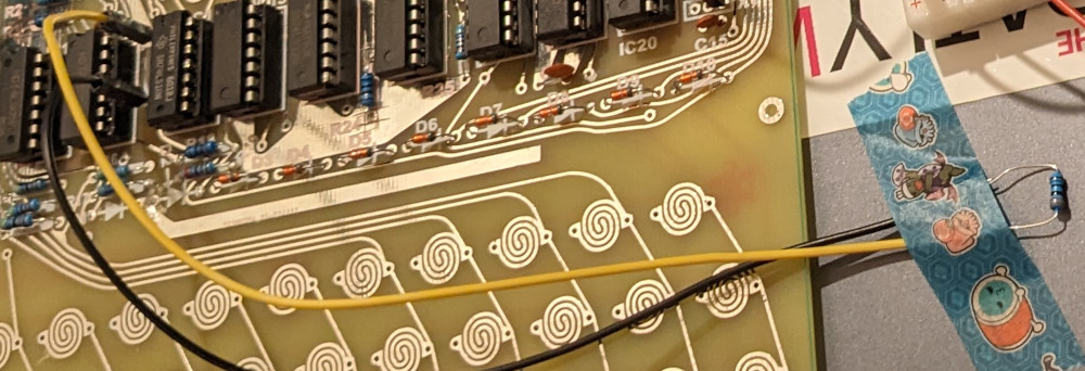
I forgot to solder on R20. This resistor is needed in the clock circuit. Fixed using jumper wires.
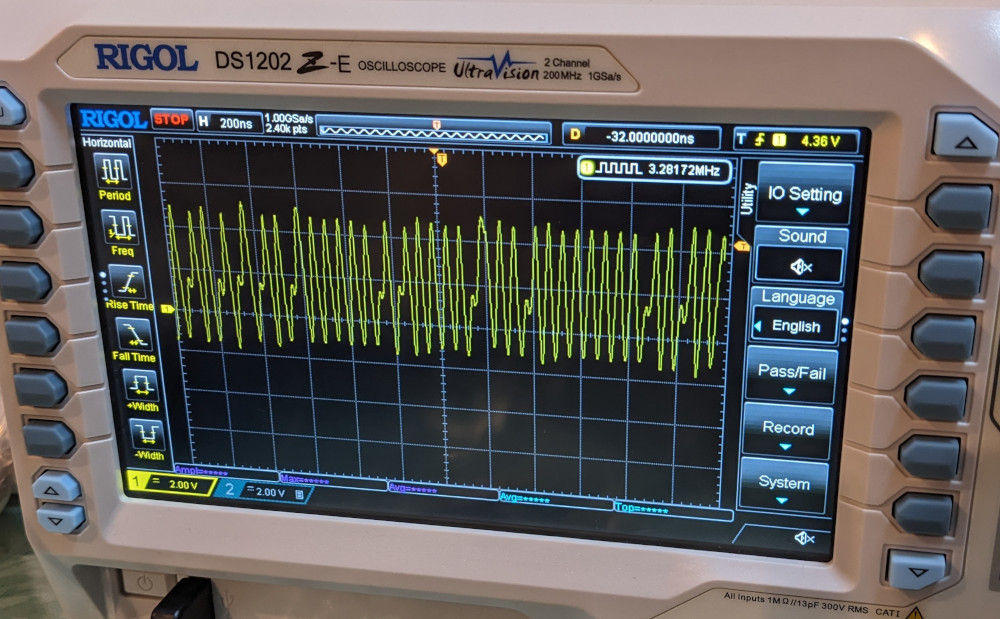
I changed the Pico’s output pin from GPIO0 to GPIO2 and failed to re-wire. I then suspected the Z80 was bad and tested it on a breadboard with the data pins tied to ground to emulate NOPs. Eventually figured out the problem (dur). It was difficult to figure out at first because the circuitry on the PCB picked up the output from GPIO2 as noise, and amplified it to produce something like a clock signal. Except that this was a very dirty clock signal (see image below)! It is interesting that the Z80 seems to detect that the clock is a little cuckoo, and while it works for a split second, it quickly calls it quits and the address bus freezes in a random state. That seems like a useful thing to be aware of! (Could of course be that this is not an intentional feature, or that it’s just seeing a HALT instruction or something.)
While testing the Z80 on the breadboard, I set the Pico’s clock output to 3.25 MHz. I then forgot to change it back to 6.5 MHz.
Temporary R20 fixDirty clock that quickly made the Z80 seize up.
RAM problem
The 2114 RAM chips originally came out of the Commodore PET that I fixed two years ago. I removed them from the PET because they were a little faulty, but kept them because they still mostly worked. Lucky! I had three, and hoped two of them would work well enough to at least get the ZX80 booted. Well, I picked a lucky one and an unlucky one. I didn’t see anything on the composite output. (Which at the time of writing is just a hole in the PCB. The ZX80 and early versions of the ZX81 don’t produce a back porch, but that problem is somehow fixed or alleviated or otherwise rendered irrelevant inside the modulator. The problem just manifests itself when you decide that the wire leading into the modulator is now going to be composite output. Back when I was looking at the ZX81 at the computer museum in Oume, I used a 555-based circuit that I got from here to fix the problem.)
Not knowing whether it’s a RAM problem or a serious problem with the PCB, I broke out my Pico-based logic analyzer. This time I didn’t bother adding resistor dividers because all Picos I have (I think I have four) turned out to be a least a little 5V-tolerant, and I wouldn’t be using the logic analyzer for a long time.
I needed to make some minor modifications to the logic analyzer code: the reset circuit in the ZX80 uses a 220K pull-up resistor (it’s very high value because it is also a 1 second (or so) RC delay circuit), and the Pico by default has pull downs active on its input GPIOs. These pull downs are much lower in value than 220K, effectively keeping reset asserted forever. (They are surprisingly low!) So the init code now looks like this:
    stdio_init_all();
    gpio_init_mask(ALL_REGULAR_GPIO_PINS);
    gpio_set_dir_masked(ALL_REGULAR_GPIO_PINS, GPIO_IN);
    gpio_disable_pulls(TRIGGER_PIN); // default is pull down; this pull down is much higher in value the the zx80's reset circuit's pull-up and therefore holds the cpu in reset
Of course, it would probably be even better if we disabled all pulls on all GPIOs. Anyway, running the logic analyzer, I quickly found a RAM problem with bit 4.
Here is the logic analyzer output with the problematic signals:
The first number is just the line number, the second number is the number of times the third and fourth numbers are repeated in the logic analyzer output (which is not in sync with the clock, but much faster). You can ignore everything that is less than around 10. In the above output, we are fetching and then executing the instruction at 0x0283~0x0285. Here is the relevant assembly source:
So we can see that we are putting 0x4028 into hl, and then incrementing hl, which means that hl should now be 0x4029. The instruction at 0x280~0x282 puts hl into 0x400a, and the instruction at 0x0283~0x0285 reads it back from the same address. So we should be putting 0x4029 in there (though not shown above, we are) and should be reading 0x4029 back. But the relevant parts of the logic analyzer output are like this:
    124      25 000a 21
    126      25 000b 40
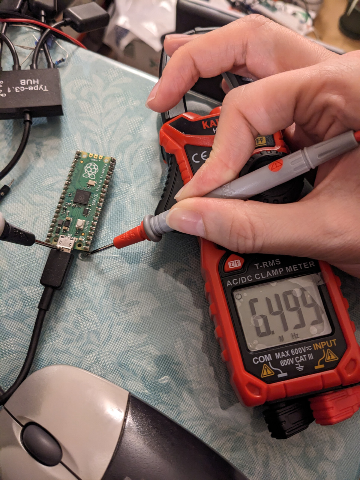
Don’t worry about this showing 000a and 000b rather than 400a and 400b. I just don’t have the higher address lines connected to the logic analyzer. We’re reading back 0x4021! That’s missing the fourth bit. So I put in the other RAM chip and bam! I see a lovely 15.something KHz signal on the through hole that would normally be occupied by one of the modulator’s leads! (Well, actually I saw a 7.65 KHz signal because I forgot to change the Pico’s clock output back to 6.5 MHz, but while that was very puzzling for a bit, it was very easy to fix.)
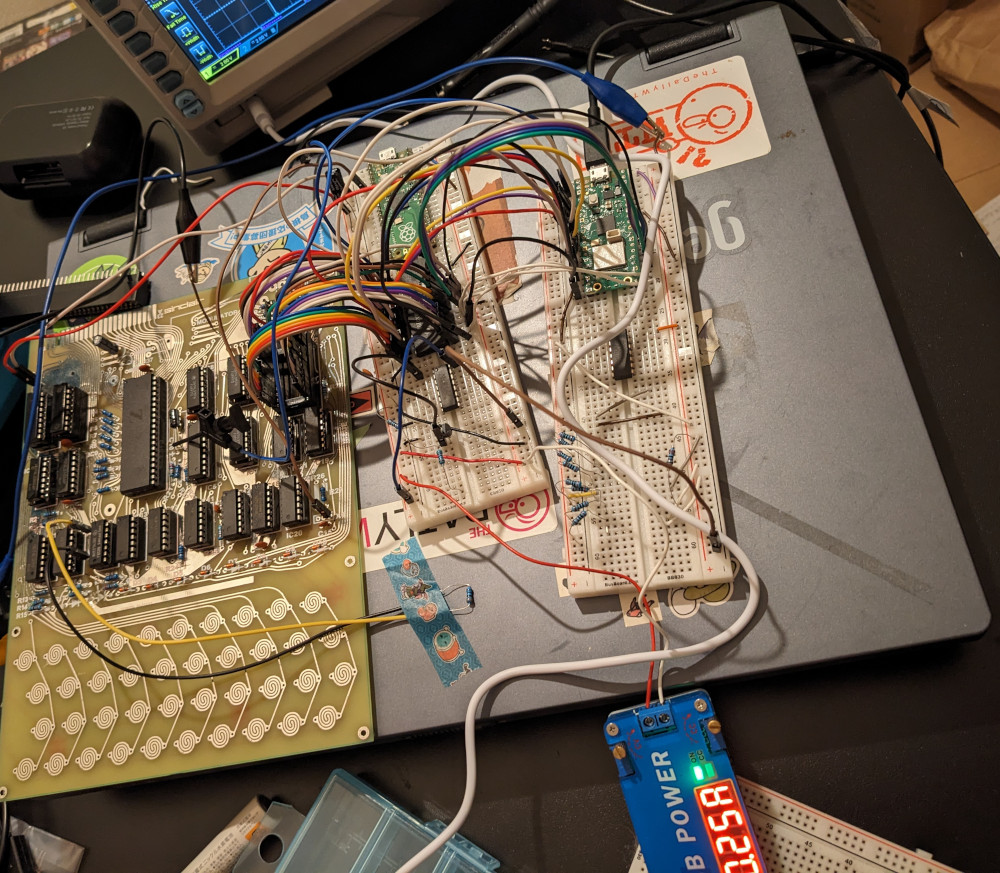
The computer resting on top of that old laptop is the newer one!It’s working! Never mind the Hitachi MB-H2 in the reflection.
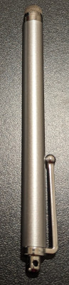
I’m currently using two of these smartphone stylus…es to operate the keyboard on the PCB (one for shift and the other for every other key).
There’s a problem though: I’m not able to press keys like ” and many other shifted keys. I haven’t properly looked into that problem yet. However, I did do a quick internet search and found someone with the same problem:
For example, all of 1 to 0 keys work but shifted, only 1 and 0 work. Some other shifted keys don’t work but there doesn’t seem to be a consistent pattern on each row. The display still flickers when say shift 2 or shift 9 (or other combinations) is pressed, just nothing else happens.
But their problem was apparently caused by using super long wires on their keyboard. I’m not doing that as far as I know?!
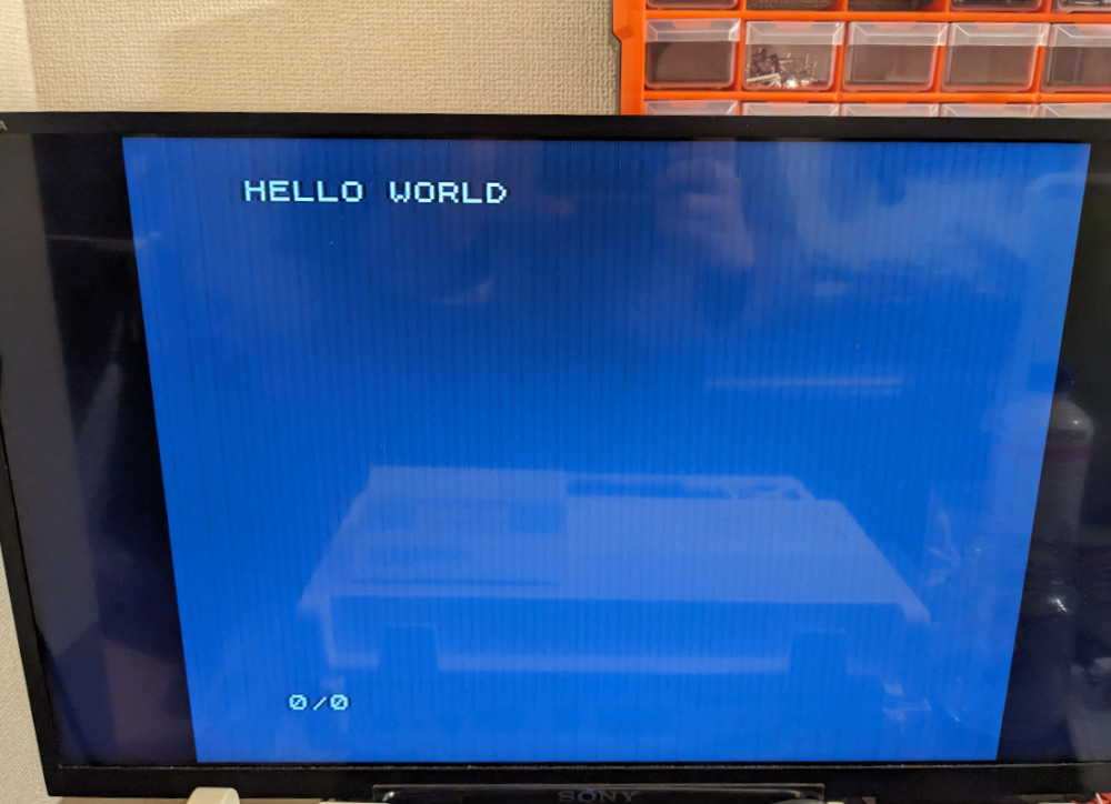
As my EEPROM is currently mounted on a breadboard and my EEPROM is 512 KB while the ZX80’s ROM is just 4 KB, I have plenty of space left. So I put the ZX81 ROM image at address 0x10000, which means I just need to change the wire on the EEPROM’s A16 pin from 0V to 5V to change to that ROM. And it works too! Plus, the keyboard layout is different, which means I’m able to access the ” key and print out a proper message rather than just numbers:
To do
Solder crystal oscillator (when I get it) and R20, and maybe headphone/microphone jacks, etc.
Backporch generator
Make a proper ROM adapter?
Get all shifted keys to work
RAM expansion
Try to load some software
Make the keyboard more ergonomic
Maybe get some kind of case
KiCad / Gerber files
Here are the SVG and KiCad files, with the above mentioned shorting issues most likely fixed. Some important notes:
I do not have permission from Grant Searle nor from the copyright holders of the original ZX80 PCB to post anything like this, and if either of these parties asks me to take my files down, I intend to comply swiftly. (I’d just need to be sure that you are who you claim to be. I apologize in advance for any grievance caused and will apologize again if grievance is actually caused.)
I used Grant Searle’s replica foils as a base and traced them in Inkscape. I performed some manual and some automated tweaks. This version of the board is likely a less faithful replica of the original board than Grant Searle’s foils. (I don’t think anything’s shifted more than even 1 mm though. Though maybe the holes are quite different. I didn’t encounter any problems with the drill holes while soldering though.)
I haven’t tested (i.e. manufactured) this version of the KiCad files, I have only ordered one set of the ZX80 boards, with the shorted pins. This issue should be fixed now, and I hope I didn’t add any new issues.
I haven’t updated this post in a while; in the meantime the above TODO list has changed as follows:
Solder crystal oscillator (when I get it) and R20, and maybe headphone/microphone jacks, etc. Very low-hanging fruit, done. The headphone/microphone jacks I got had thicker pins that I had expected, and I had to widen the holes in the PCB a little bit.
Get all shifted keys to work ← While it’s already almost one year ago, I had a good look at what’s going on. I’m betting that it’s my breadboard-based ROM adapter that is adding capacitance into the circuit. Together with the resistors (the ones positioned between the ICs and the keyboard), I observed a long RC delay that prevents signals from the key press to rise/fall (can’t remember which) in time. I used lower value for the aforementioned resistors but couldn’t get all keys to work while using the 4 KB (ZX80) ROM. However, using the ZX81 ROM, it looks like the programmers gave us more time and everything just works (I already replaced the resistors so not sure if it worked with the original ones). Thus I’m usually using the ZX81 ROM.
Wow, two weeks have passed since Christmas. Wow, we’re one week into 2024. Happy New Year!
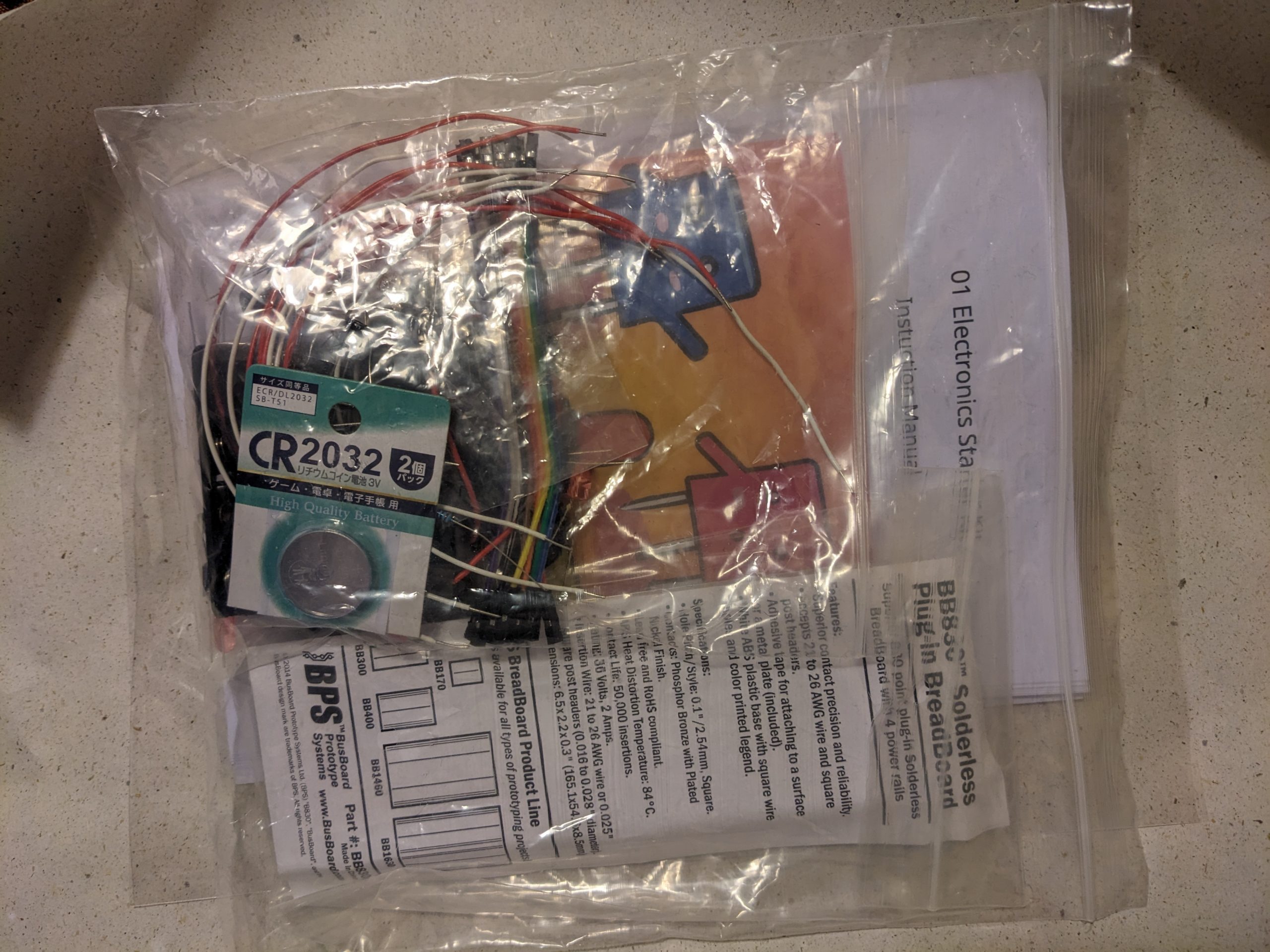
I have an 8-year-old niece and I thought I’d give her an electronics kit for Christmas. Well, it seems that in modern electronics kits, electronic components are covered in a bunch of plastic, making everything look kind of childish. They are a little safer I suppose because they are too big to be swallowed. But at least I (as a child) didn’t really like stuff with a “Fisher-Price” look, I tended to want the real deal. So I decided to make my own electronics kit with my own manual! I just put in a few components I mostly had on hand (I also washed them before, just in case I’d used them somewhere dirty before):
5 red LEDs with a low forward voltage (around 1.7V), this way you can show that they light up (barely) with very fresh alkaline batteries. (Note: most red LEDs have a higher forward voltage of 1.85V or so, and wouldn’t light up at all)
5 blue LEDs
5 white LEDs
5 100 uF (or so) electrolytic capacitors
5 470 uF (or so) electrolytic capacitors
5 470 ohm (or so) resistors
5 2n2222 transistors
2 CR2032 batteries
2 CR2032 battery holders (the ones I bought can just barely fit into a breadboard)
Optional: 4x AA/AAA battery holder and AA/AAA batteries (referenced in text, so make sure to remove reference if you don’t want to include them)
Some wires
1 breadboard
I didn’t include a multimeter, but if the child’s/person’s household doesn’t have one, it might make sense to include one. (The manual doesn’t really fully explain how to use multimeters, however.)
In the manual, the first experiment makes use of the fact that blue and white LEDs have a forward voltage that is quite compatible with CR2032 coin cells. The experiment just sandwiches a coin cell between an LED’s legs.
Then the manual explains that this doesn’t work with red LEDs and a resistor is used to limit the current. (Actually it will probably be okay for a while because coin cells don’t give a lot of current.) Some effort is made to explain voltage, current, and resistance, but (hopefully) on a level that is (possibly, barely) understandable by an 8-year-old.
A little later, capacitors are explained a bit. And transistors. The final experiment is a circuit that has some twinkling LEDs. The following is a similar circuit, just to give you an idea:
Old video shot on a potato.
And here’s the completed set, just before wrapping it:
DIY electronics kit, complete with “Instuction Manual” (d’oh!)
The manual is in .odt format (can be opened in LibreOffice and similar) and you can download it below. It includes some copyrighted pictures from other sites (the battery pic, the diode symbol(s), the transistor pic, the capacitor pic, and the empty breadboard pics). The front page image is AI-generated but heavily edited. Note: LibreOffice may have a bug that prevents emoji from being included in exported PDF files. My printed booklet ended up not containing emoji and I noticed only much later. :(
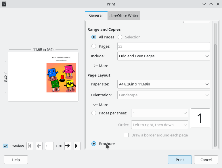
I made a booklet using the following LibreOffice print settings and a stapler:
Make sure to select “A4” and “Landscape” before selecting “Brochure”, otherwise LibreOffice might get the layout wrong.
If you want to customize the manual for somebody else, you should read through the entire thing. Edit it to your heart’s content. There is at least one reference to “8-year-olds”, maybe do a search. There are references to “dad or uncle” and “parents”. The “license” is “public domain”. Feel free to give credit, but you don’t have to.
Or alternatively: how to get svg2shenzhen to recognize your drill paths as drill holes
(My) rationale: there is an Inkscape extension called svg2shenzhen. This extension creates Gerber and KiCad files that can be used to create printed circuit boards, from standard SVG files. Also, this extension has a funny name. Older, DIY printed circuit boards are just a high-DPI bitmap. Using Inkscape and this extension, you can trace the bitmap and then convert it to Gerber. However, most PCBs (especially old PCBs) need to have holes drilled. The drill locates are just circles in the bitmap, and after tracing, they’re just paths. The svg2shenzhen extension (at the time of this writing) detects circles in a certain layer as locations that need to be drilled, but not paths.
I’m not an Inkscape expert, but AFAIK Inkscape (at the time of this writing) doesn’t have a built-in tool to convert (mostly) circular paths to circles. So I wrote a simple extension that does this! It works fine on Linux. Not so sure about Windows.
Extensions are made of only two files, a file that describes the extension, and the extension code (which is in Python in many cases). These two files just have to be placed into the location shown in Edit -> Preferences -> System -> User extensions, which in my case is ~/.config/inkscape/extensions/.
Here are the two files, you can copy them into a text editor like Kate or gedit or Notepad, what have you, and save them into the above directory. I recommend keeping my file names, path2circle.inx and path2circle.py. Note, some skeleton code in path2circle.py was generated by ChatGPT, though it was quite wrong. That’s where some of the verbose comments and extraneous code came from.
import inkex
from inkex import Circle

class Path2Circle(inkex.EffectExtension):
    def effect(self):
        # Iterate through all the selected objects in the SVG
        for node in self.svg.selection:
            # Check if the object is a path (or any other object type)
            if node.tag.endswith("path"):
                # Get the bounding box of the object
                x, y, width, height = self.get_object_dimensions(node)
                x = x.minimum
                y = y.minimum
                # with open('/path/to/debug/directory/debug_output.txt', 'a') as f:
                    # print(f"Object Dimensions: x={x}, y={y}, width={width}, height={height}", file=f)
                layer = self.svg.get_current_layer()
                diameter = min(width, height)
                layer.add(self.add_circle(x, y, diameter/2))

    def add_circle(self, x, y, radius):
        """Add a circle at the given location"""
        elem = Circle()
        elem.center = (x+radius, y+radius)
        elem.radius = radius
        return elem

    def get_object_dimensions(self, object_node):
        # Get the bounding box of the object
        bbox = object_node.bounding_box()

        # Extract the bounding box coordinates
        x = bbox.x
        y = bbox.y
        width = bbox.width
        height = bbox.height

        return x, y, width, height

if __name__ == '__main__':
    Path2Circle().run()
To use the extension, you probably first need to restart Inkscape. (You do not need to restart Inkscape after changing the extension, however.) Select all the paths you’d like to convert, and then hit Extensions -> Custom -> Path2Circle. Note: the extension doesn’t actually care if the paths even remotely look like circles, so make sure to select the correct paths. You can easily modify the extension to calculate the radius differently, or e.g. replace paths with other objects, such as squares, rectangle, or ellipses. Let me know if you need help doing that.
In a previous post, we did some warmups — playing MSX games using a fake PS3 controller. In this post, we’ll be using GP2040-CE to control a Nintendo Switch. (No analog stick support implemented at the moment, but it wouldn’t be hard.) At the time of writing, most of the code to do this is already there! And I’m sure there will be support for USB-HID controllers in no time, so this post will probably be outdated soon. Update: Analog is implemented too, and the diff below has been updated.
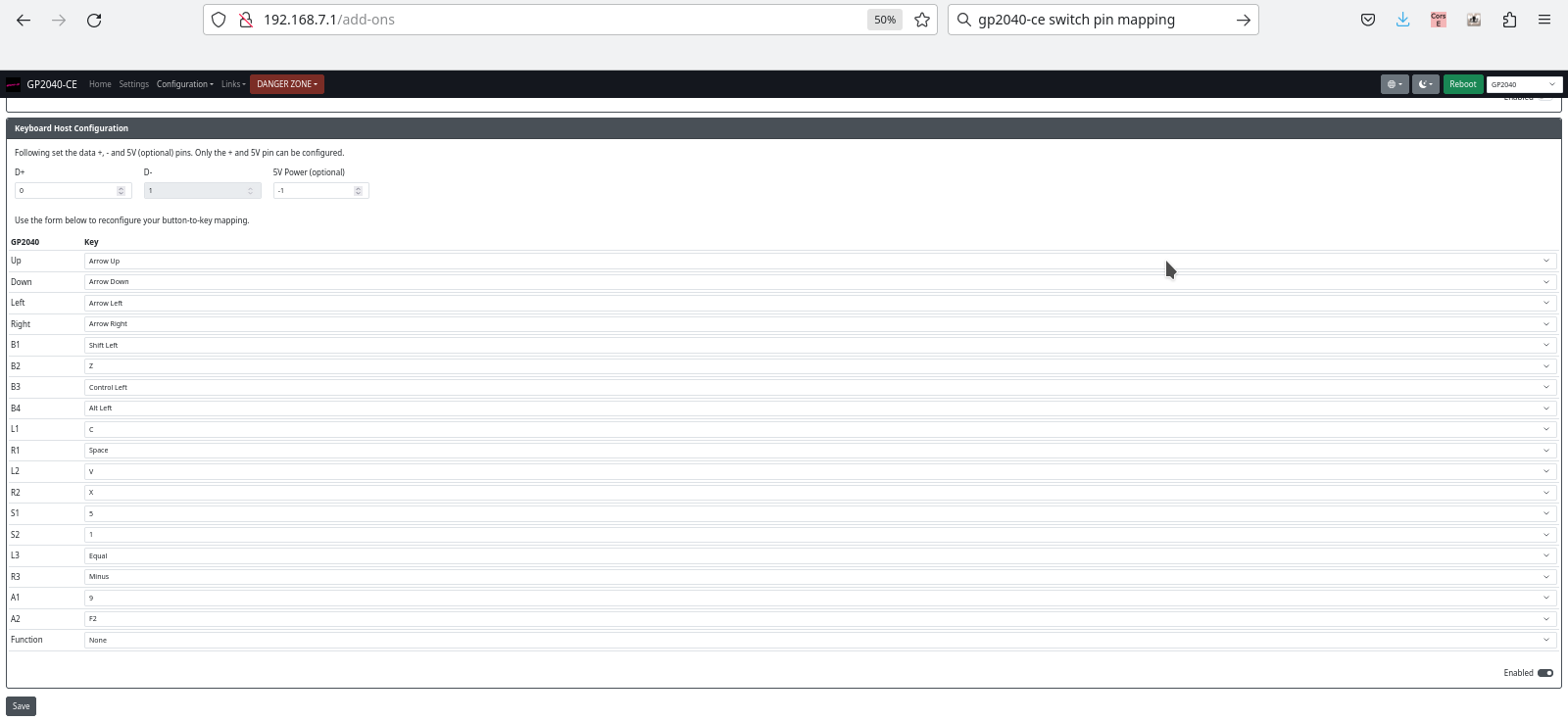
Anyway, you just need to put GP2040-CE on your Pico and get into the web configuration. In add-ons, you enable keyboard support, and then set up the “Keyboard Host Configuration”, which looks like this:
GP2040-CE keyboard mapping and other configuration
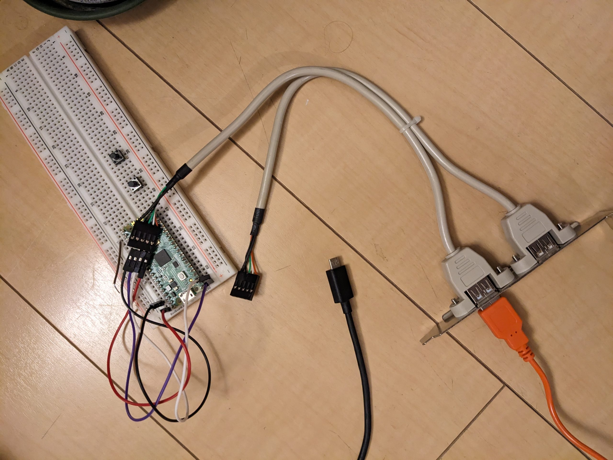
Then you can connect a generic USB keyboard to the Raspberry Pi Pico, and connect the Pico to the Nintendo Switch. (For electrical reasons, I do not recommend setting a pin for 5V power here, and just putting the host USB +5 on the VBUS pin of the Pico.)
Things that could come in handy: Breadboard, Raspberry Pi Pico, USB port that can be connected to one of the Pico’s GPIO pins
If everything works and you can control Sonic using your keyboard, great, you can move on to the next step! If it didn’t work, it probably won’t magically get better from here on out, so make sure to check those connections. The green/white wires can be D+/D- or D-/D+!
Now we’ll perform a small modification to the existing code. I’m basing my work on commit 961c49d5b969ee749ae17bd4cbb2f0bad2380e71. Beware, this may or may not work with your controller. I’d recommend taking a look at the above-mentioned previous post where we modify a Pico-PIO-USB example and to check if your controller behaves the same way. I have only two controllers to test with, and I only tested with one! Anyway, here’s the diff:
Good luck. Miraculously, everything worked perfectly for me. The keyboard worked immediately, the above code modification worked immediately without having to do any debugging, and I’ve gotta say, my fake PS3 controller feels quite okay! (Note that you will have to press the PlayStation button after connecting your PS3 controller.)
Symptoms on real PS3: probably “crazy behavior”, I didn’t actually test on a real PS3. Symptoms when connected to a computer with a program open that displays the gamepad status: random button presses, button “flickering”, buttons going on and off randomly, possibly depending on how the controller is held.
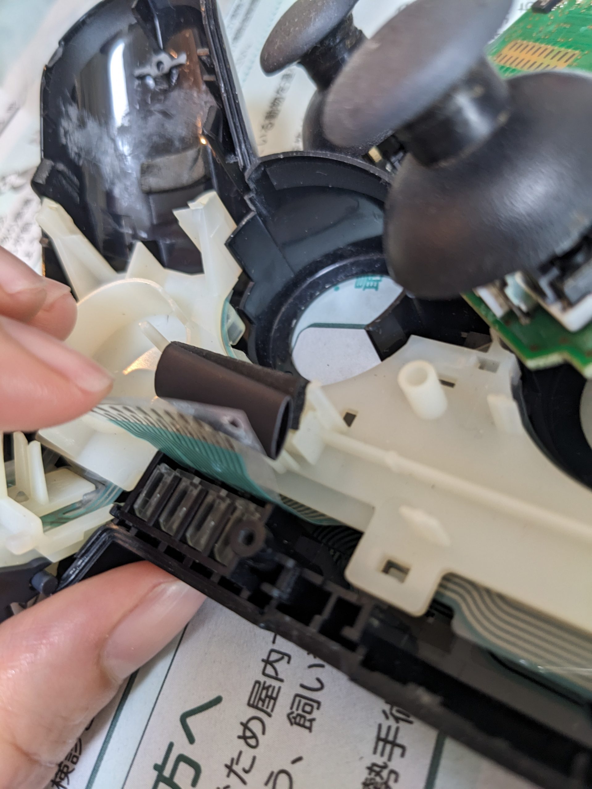
Cause in my case: rubber cushion is worn out, and/or physical damage to the controller’s case and/or loss of one of the screws. The rubber cushion sits on a piece of plastic, and a flex cable is sandwiched between the rubber cushion and the PCB. If the rubber cushion loses some of its original height, for example due to wear, or if one of the controller’s screws are lost and the PCB isn’t pressed as hard against the rubber cushion as it used to, buttons will randomly appear pressed or unpressed. (When there is absolutely no connection between the flex cable and the PCB, all buttons will appear pressed. When the connection is flaky, buttons may appear pressed all the time, or go on and off.)
Fix: adding a little height to the cushion fixed the problem for me.
In this pic, I’m holding the flex cable with one of my fingers. The tube (it’s a piece of heat shrink, actually) is what I added to improve contact between the flex cable and PCB. The original rubber is still there.