Introduction
The YM3012 IC is a DAC that requires two external op amp circuits and turns a serial digital audio signal consisting of a 10-bit mantissa and 3-bit exponent into an analog signal. (Apparently there is a similar DAC that takes the same input but produces mono output, the YM3014. This would perhaps make this project closer to that one.)
I am currently investigating a fault in an audio module (SFG-01) for certain MSX computers (mostly Yamaha). This audio module is pretty capable and sports a YM2151 FM audio synthesis chip and comes with MIDI input and output ports, a connector for a digital piano keyboard, and software to use the keyboard of course. (I actually never checked if the software is in the module or in the computer.) See this for more information on the SFG-01: https://www.msx.org/wiki/Yamaha_SFG-01.
The fault becomes apparent as soon as two keys are pressed at the same time on the digital piano keyboard. You get a kind of growling/distorted effect. The audio doesn’t sound clean. (Head to the video section below to hear what it sounds like.) My first thought was, that sounds like an analog problem. Aw, I wish. I replaced a couple capacitors without any improvement whatsoever. The removed capacitors all tested fine out-of-circuit, too. A few people said it could be a problem with the op amps. One (relatively) quick way to check if that is the case, is to replace the op amps and try again. But why do it the quick and simple way (with possibly nothing to show at the end) if you can do it the slow and complicated way (with maybe something to show at the end)?

The Raspberry Pi Pico is very good at IO. Not only do we have a lot of pins, but we can read from and write to them very, very fast. However, we aren’t going to go that fast today actually. Neither are we going to be using a lot of pins. In order to build a DAC, we need to read the CLOCK φ1, SD (DATA) and SAM1 and/or SAM2 pins. And then we need output, which in my case is a single pin outputting PWM audio. (It sounds okay, probably not exactly Hi-Fi.) My implementation only reads SAM1 and only outputs a single channel, completely discarding the other channel. It wouldn’t be too hard to get the second channel to work too — the Pico is a dual-core jobby after all, so you could just run the same code on the second core and it’d work. (As there isn’t really a lot of post-processing going on at all, you could most likely even get it to work with just a single core, but I haven’t tried.)
So, in order to test if our DAC, or one of the op amp circuits, or the filter circuits are misbehaving, we just need our Raspberry Pi Pico and check if we’re getting the faulty audio there too. If yes, the DAC is innocent. If no, the DAC or related circuitry would be implicated.
PWM audio
Researching PWM audio on the Pico, I first came across this YouTube video: https://www.youtube.com/watch?v=rwPTpMuvSXg. It turns out, however, that PWM audio is discussed in https://datasheets.raspberrypi.com/rp2040/hardware-design-with-rp2040.pdf, and the creator of the above YouTube video had mostly taken the circuit from there. Basically, you need a medium-sized capacitor to remove the DC bias, some resistors and smaller caps to filter out high-frequency components, and optionally a buffer IC. It’s all right to use a digital buffer IC (I’m using a 74-series logic hex inverter), which then drives the above-mentioned resistors and caps. (The Pico can’t output a lot of current, so I decided to include the buffer, as recommended in the PDF.)
Overview
Since the MSX and its audio module and the keyboard are museum exhibits, and the museum isn’t exactly next door (fortunately not too far away though), I only had limited time to experiment with the original hardware. So what do you do in such a case? Well, I think we all agree that any sane person would immediately head to the internets and check if anyone’s ever implemented the YM2151 (the FM synthesis chip) on an FPGA. (Well, any sane person who owns an unused FPGA. Mine is an UPduino that I bought a couple years ago. They’re actually more expensive now than back then.) As a bonus, if it turns out that the DAC is fine, we should (sometime in the future) be able to hook up our FPGA to the SFG-01 and see if it produces the same weird distorted sound. If it doesn’t, we can be reasonably sure that the YM2151 on the SFG-01 is the one causing the weird sound. (Assuming there are no bad solder joints, etc.)
It turns out that the the YM2151 does indeed exist in the form of Verilog code: https://github.com/jotego/jt51. Amazing! Thank you very much. Impressive. 😳 So all we have to do is:
- Put this on our FPGA
- Find a way to control the FPGA
- Connect the FPGA’s output to our DAC and experiment until it sounds okay
On 1: unfortunately our FPGA is a little bit too small to fit the entire thing. Also, the inputs and outputs are slightly different from the original chip! What do we do? Lowering the footprint of JT51 (YM2151 Verilog clone) to work on smaller FPGAs, specifically the ICE40UP5K (Part 1? WIP? Progress diary?) / UPduino mini-tutorial
On 2: I took this: https://github.com/iComputer7/RaspiPicoVGM.git. Nice work, thank you very much! And modified it to only support the YM2151, remove SD card support, and instead read the VGM data from a header file. My modified code is at https://github.com/qiqitori/RaspiPicoVGM.
On 3: that’s this post, I guess.
Debugging methodology
There were many hours spent debugging this. How do you even debug audio that sounds wrong somehow? Well, as with all debugging, you break things up into smaller things that you can actually verify to be correct (or prove incorrect):
- Make sure the digital data you are receiving on the Pico is the same as what the FPGA is supposed to be putting on the wire.
- Make the FPGA always output the same dummy value. Not the case. The most significant bit is flipped sometimes.
- Check if the Pico’s pio_sm_is_rx_fifo_empty() function is lying or something. Yes, looks like it.
- Implement a workaround. (More on that later in this post.)
- Audio sounds slightly better but overall still crappy.
- Forget about the mantissa + exponent algorithms for a second and make the FPGA output straight 16-bit signed PCM.
- There’s a hiss but generally speaking it sounds pretty good!
- Play around with the PWM audio parameters
- Oh wow, the hiss is gone and things sound almost perfect.
- Raw PCM audio sounds good, but mantissa + exponent audio still doesn’t.
- Make the FPGA output PCM for one sample, and mantissa + exponent of the exact same sample on the next sample.
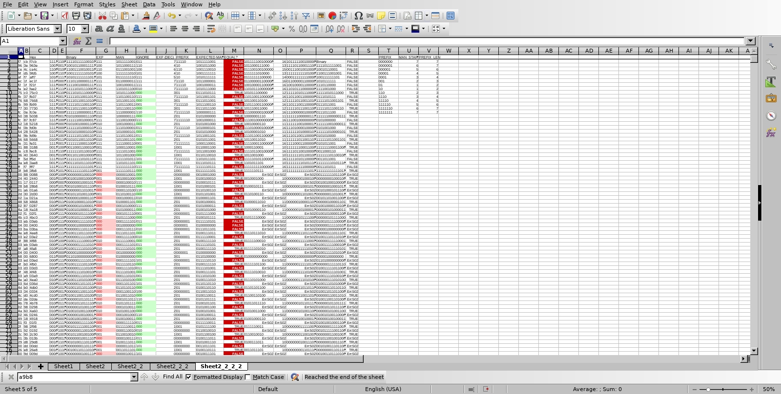
- Put a hexdump in a spreadsheet and see if we can spot the problem. The mantissa + exponent samples should be exactly the same (but with some of the lower bits all 0s), but often they’re somewhat different.
- Fix some issues that we introduced in the FPGA code
- Output changes continuously and must be latched on the first clock cycle of a new sample
- reg/wire confusion
- Pico DAC’s mantissa + exponent code was slightly wrong too
The thing mentioned in 1-2 could be a bug in the Pico SDK (or documentation). I’ll probably look into that at some point. The workaround consists of reading from the FIFO twice.
Here’s a screenshot of the aforementioned spreadsheet:
I also used a tiny script (that I’m including below, just for my own convenience for when I need to get back to something related) to convert a hex dump into audio, using xxd and sox:
#!/bin/bash

# assumes a log file generated e.g. like this: minicom -C sample_dump1.log -D /dev/ttyACM0

tail -n +2 $1 > $1.trunc # get rid of hello world debug output
xxd -p -r $1.trunc > $1.trunc.raw
sox -c 1 -r 62000 -t u16 $1.trunc.raw -b 16 -e signed-integer $1.trunc.wav
Pic/audio/video
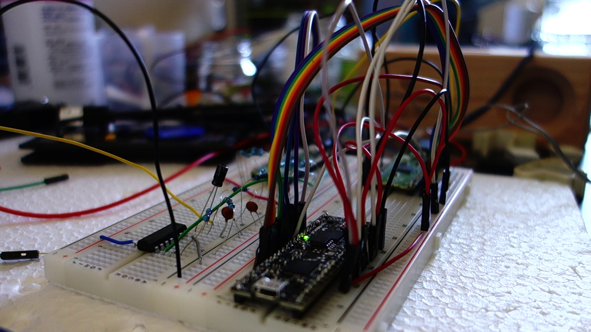
I obtained a VGM for the YM2151 from this page: https://vgmrips.net/packs/pack/fantasy-zone-ii-dx-sega-system-16c. I chose “10 Years After ~ Cama-Ternya [Demo]”, and converted this from VGM to a header file for use with RaspiPicoVGM using xxd -i. Below is some audio of this VGM being played back using the above pictured setup. Note that it isn’t perfect, most likely due some issues on the FPGA side:
(Here’s a YouTube video of how this song is actually supposed to sound: https://www.youtube.com/watch?v=5sBDx56lv7g)
The below video shows the pico_ym3012 connected to the SFG-01 using tiny test clips, fully reproducing the growling/distorted sound that is the source of this whole investigation.
Verilog lessons learned
- If you have a
`definein one file and an`ifdefin another file, that`ifdefcould very well evaluate as true. - Latching is pretty important
- Executing
alwaysblocks on the correct conditions is pretty important - The synthesis tool won’t always catch wire vs. reg mistakes
- Verilator will catch some things that yosys will just interpret in the probably correct way
The code
The code is also available at https://github.com/qiqitori/pico_ym3012/. License is GPLv3 for ten years after release. If there is no update saying something to the contrary, consider it public domain. I have only reproduced the major bits below.
ym3012_dac.c:
#include <stdio.h>

#include "pico/stdlib.h"
#include "pico/multicore.h"
#include "hardware/pio.h"
#include "hardware/uart.h"
#include "hardware/pwm.h"
#include "ym3012_dac.pio.h"
#include "hardware/irq.h"  // interrupts

#define PIN_BASE 0
#define AUDIO_PIN 28

// #define DEBUG 1
// #define JT51 1

#ifdef JT51
#define DESIRED_SAMPLE_RATE 62000 // 4 MHz VGM
#else
#define DESIRED_SAMPLE_RATE 57000 // 315/88 MHz / 2 / 32
#endif

uint16_t samples[110000] = { 0 };
uint16_t last_sample;

int main() {
#ifdef DEBUG
    stdio_init_all();
    sleep_ms(5000);
    printf("Hello world\n");
#endif

    // Init PWM for audio out
    gpio_set_function(AUDIO_PIN, GPIO_FUNC_PWM);
    int audio_pin_slice = pwm_gpio_to_slice_num(AUDIO_PIN);

    // Setup PWM for audio output
    // We run at around 125 MHz. If we set the pwm counter's top value (== wrap value) to 8192 (generally, bigger is better), the pwm counter can reach the top value 15258.7890625 times per second, which would be our effective sample rate. (Calculation: 125000000/8192)
    // However, our target sample rate is larger than that. Let's say if we wanted 44100 Hz: 125000000/44100 = 2834.46712018, so that's the max top value we should set.
    // However, our target sample rate is even larger than that. Let's say we want 60 KHz. Then the max top value is 2083.33333333.
    // In that case, our samples' max loudness should be about half that, 1041.66666667.
    // That's pretty close to 1024. That's good.
    // Let's not hard-code this but calculate based on the desired sample rate.
    // Note that the desired sample rate depends on the VGM tune played.
    uint16_t pwm_wrap = clock_get_hz(clk_sys)/DESIRED_SAMPLE_RATE-24; // TODO: Check if -24 actually improves anything (original intent is to buy microcontroller some time to move to the next sample -- if we don't have enough time, pwm_set_gpio_level might not make it in time and the entire next PWM cycle would be played using the level of the previous sample. I think so anyway.)
    pwm_config config = pwm_get_default_config();
    pwm_config_set_clkdiv(&config, 1.0f);
    pwm_config_set_wrap(&config, pwm_wrap);
    pwm_set_gpio_level(AUDIO_PIN, 0);
//     pwm_set_phase_correct(audio_pin_slice, true); // TODO: maybe test if this changes anything?
    pwm_init(audio_pin_slice, &config, true);

    // Init state machine for PIO
    PIO pio = pio0;
    uint sm = 0;
    uint offset = pio_add_program(pio, &ym3012_dac_program);
    ym3012_dac_init(pio, sm, offset, PIN_BASE);

#ifdef DEBUG
    for (int j = 0; j < 15; j++) {
        for (int i = 0; i < 110000; i++) {
            samples[i] = ym3012_dac_get_sample(pio, sm);
        }
        for (int i = 0; i < 110000; i+=8) {
            printf("%04x %04x %04x %04x %04x %04x %04x %04x\n", samples[i], samples[i+1], samples[i+2], samples[i+3], samples[i+4], samples[i+5], samples[i+6], samples[i+7]);
        }
    }
#else
    while (true) {
        last_sample = ym3012_dac_get_sample(pio, sm); // same as above
//         printf("%04x\n", last_sample);
        last_sample = last_sample >> 5;

        pwm_set_gpio_level(AUDIO_PIN, last_sample);
    }
#endif
}
ym3012_dac.pio:
.program ym3012_dac

; // WARNING you need to switch between JT51/YM2151/PCM code yourself by commenting/uncommenting the relevant PIO code blocks below!

; for man+exp (YM2151):
    set x, 12            ; Preload bit counter, delay until eye of first data bit
    wait 1 pin 1        ; Wait for SAM HIGH // WARNING WARNING WARNING WARNING WARNING WARNING WARNING WARNING change required on JT51: wait 0 pin 1
    wait 0 pin 1        ; Wait for SAM LOW // WARNING WARNING WARNING WARNING WARNING WARNING WARNING WARNING change required on JT51: wait 1 pin 1
    ; ignore first three bits, as specified in data sheet
    wait 1 pin 2        ; Wait for clock HIGH
    wait 0 pin 2        ; Wait for clock LOW
    wait 1 pin 2        ; Wait for clock HIGH
    wait 0 pin 2        ; Wait for clock LOW
    wait 1 pin 2        ; Wait for clock HIGH
bitloop: ; Loop x times
    wait 0 pin 2        ; Wait for clock LOW
    wait 1 pin 2        ; Wait for clock HIGH
    in pins, 1          ; Sample data
    jmp x-- bitloop     ;

; for JT51 linear signed 16-bit PCM:
; for linear s16:
;    set x, 15            ; Preload bit counter
;    wait 0 pin 1        ; Wait for SAM HIGH
;    wait 1 pin 1        ; Wait for SAM LOW
;bitloop: ; Execute following code x+1 times
;    wait 1 pin 2        ; Wait for clock HIGH
;    in pins, 1          ; Sample data
;    wait 0 pin 2        ; Wait for clock LOW
;    jmp x-- bitloop     ;

% c-sdk {
#include "hardware/clocks.h"
#include "hardware/gpio.h"

// #define YM3012_CLK 2000000 // for 4 MHz tunes
#define YM3012_CLK 1790000 // SFG-01 runs at NTSC speed
#define CLK_MULTIPLIER 8 // we need to run faster because we do "wait 1"/"wait 0"s for every transition in PIO code (and have some other extra instructions too)
#define NEGATE_EXP 1
// #define LINEAR_PCM_S16_INPUT 1
// #define DEBUG 1

static inline void ym3012_dac_init(PIO pio, uint sm, uint offset, uint pin_base) {
    pio_sm_set_consecutive_pindirs(pio, sm, pin_base, 3, false);
    pio_gpio_init(pio, pin_base);

    pio_sm_config c = ym3012_dac_program_get_default_config(offset);
    sm_config_set_in_pins(&c, pin_base);
    // Shift existing values to the right when new value comes in
    // The YM3012 receives D0 first, which is the least significant bit
#if LINEAR_PCM_S16_INPUT
    sm_config_set_in_shift(&c, true, true, 16); // signed 16-bit linear, shift to right
#else
    sm_config_set_in_shift(&c, true, true, 13); // man+exp, 10+3 bits, shift to right
#endif
    sm_config_set_fifo_join(&c, PIO_FIFO_JOIN_RX); // appears to be necessary??
    float div = (float)clock_get_hz(clk_sys) / (YM3012_CLK*8); // TODO: 4 * actual clock rate would be nice // "For example, the YM2151 internally divides the clock by 2, and has 32 operators to iterate through. Thus, for a nominal input clock of 3.58MHz, you end up at around a 55.9kHz sample rate." https://github.com/aaronsgiles/ymfm/blob/main/README.md
    sm_config_set_clkdiv(&c, div);

    pio_sm_init(pio, sm, offset, &c);
    pio_sm_set_enabled(pio, sm, true);
}

static inline uint16_t ym3012_dac_get_sample(PIO pio, uint sm) {
    // 10-bit read from the FIFO (data is left-justified)
    uint16_t data_and_exp, data, result, leading_ones;
    uint8_t exp;
    io_rw_32 *rxfifo_shift = (io_rw_32*)&(pio->rxf[sm]);
    while (pio_sm_is_rx_fifo_empty(pio, sm))
        tight_loop_contents();
    uint16_t rxfifo_contents = *rxfifo_shift; // HACK. If we don't read this twice we may get a stale?? value with the last bit sometimes missing. (HOWEVER reading thrice we get something stale again. Though maybe we're just a little late when reading the third time?) (see example below)
#ifdef LINEAR_PCM_S16_INPUT
#ifdef DEBUG
    return (uint16_t)((int16_t)(*rxfifo_shift >> 16)); // don't want that ugly offset when we're debugging
#else
    return (uint16_t)((int16_t)(*rxfifo_shift >> 16)+32768);
#endif // DEBUG
#else // !LINEAR_PCM_S16_INPUT:

    data_and_exp = (uint16_t)(*rxfifo_shift >> 19);

#ifdef NEGATE_EXP // not needed on JT51
    exp = ~((data_and_exp) >> 10) & 0b111; // top 3 bits, negated
#else
    exp = ((data_and_exp >> 10) & 0b111); // top 3 bits
#endif

    data = data_and_exp & 0b1111111111; // lower 10 bits
    if (exp == 0) { // probably doesn't happen on the JT51 at least, and shouldn't happen on YM2151 according to datasheet
        result = 0; // according to jt51_exp2lin.v
    } else {
#ifdef JT51
        result = (data << (exp-1));
        // For signed numbers (first bit of mantissa is 1) we need to sign extend by adding a bunch of ones.
        // The number of ones to be added is: 16 (because uint16_t) - (left_shift_amount (== exp-1) + 10 (mantissa length)).
        // We can create a value with the specified number of leading ones by left shifting a value that is all ones.
        // We need to shift by (16-number_of_desired_leading_ones) (e.g., 0xffff with 16 leading ones can only be achieved by left shifting by 0).
        // 16 - (16-((exp-1)+10)) = 16 - (16 - (exp-1) - 10) = 0 - -(exp-1) - -10 = (exp-1) + 10 = exp + 9
        leading_ones = 0xffff << ((exp-1) + 10);
        if (data & (1<<9)) // test for first bit of mantissa
            result |= leading_ones; // add leading ones
        result = (int16_t)result + 32768;
#else
        result = data << 6;
        result = result / (2<<(exp-1));
#endif
    }

    // related to above HACK:
    // example output of below printf demonstrating the stale output when reading the first and third times
    // first read: 0
    // third read: 715653120 or 2863136768
    // second read (>> 19): always 5461
//     0 715653120 5461 341 2 170
//     0 2863136768 5461 341 2 170
//     0 2863136768 5461 341 2 170
//     0 715653120 5461 341 2 170
//     0 2863136768 5461 341 2 170
//     0 2863136768 5461 341 2 170
//     0 715653120 5461 341 2 170
//     0 715653120 5461 341 2 170
//     0 715653120 5461 341 2 170
//     0 2863136768 5461 341 2 170
//     printf("%u %u %u %u %u %u\n", rxfifo_contents, *rxfifo_shift, data_and_exp, data, exp, result);

    return result;
#endif // LINEAR_PCM_S16_INPUT
}
%}
The scaffolding is basically the same as usual. See the Github repository for details.