Well, I finally had a chance to see a few of those infamous RIFA metallized paper capacitors first hand!
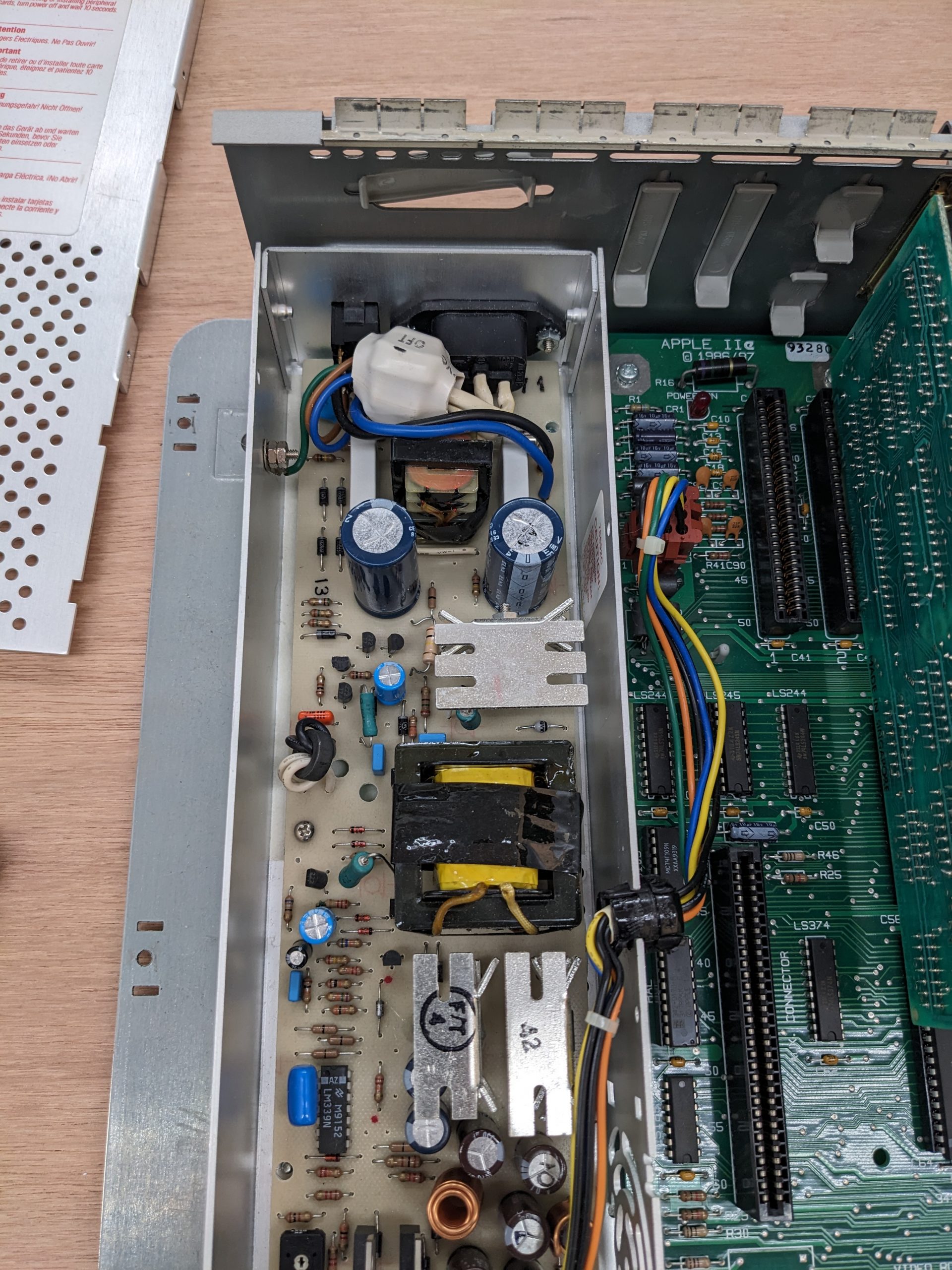
Yesterday, I had a look at two Apple IIe machines. One was from 1987. This computer works and is in really good condition and bears the signature of Steve Wozniak. I thought it would be a good idea to go and check for RIFA capacitors in there, but there weren’t any. Here’s a picture of its really clean power supply:
I am guessing that those two white things are the noise suppression caps.
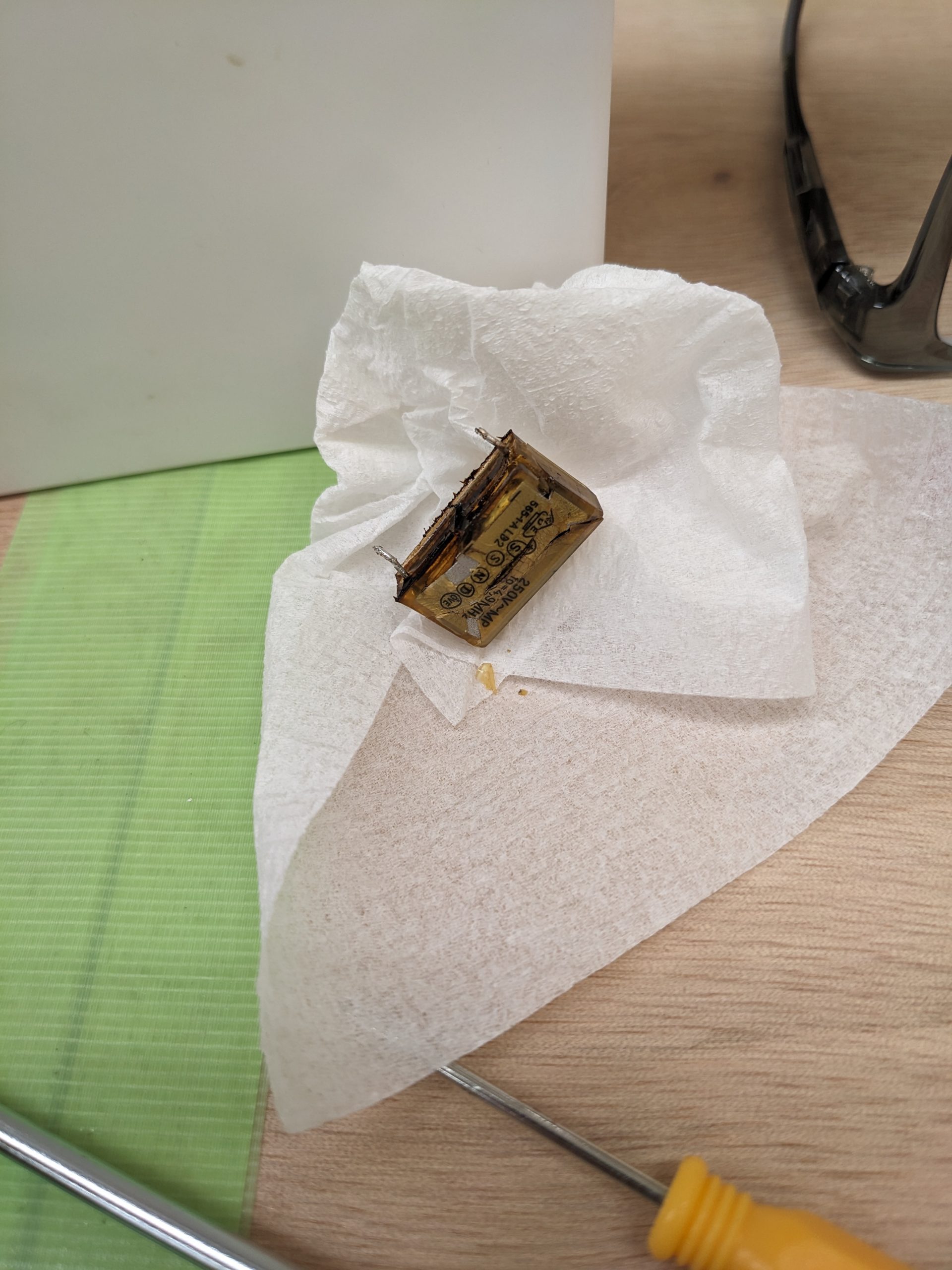
The other Apple IIe doesn’t work. The person running this machine immediately switched off the mains line when smoke started coming out of its power supply. That’s good! The capacitor didn’t go short, and the fuse was still intact. Maybe it even reduced the amount of smoke and brown juice sprayed about its perimeter.
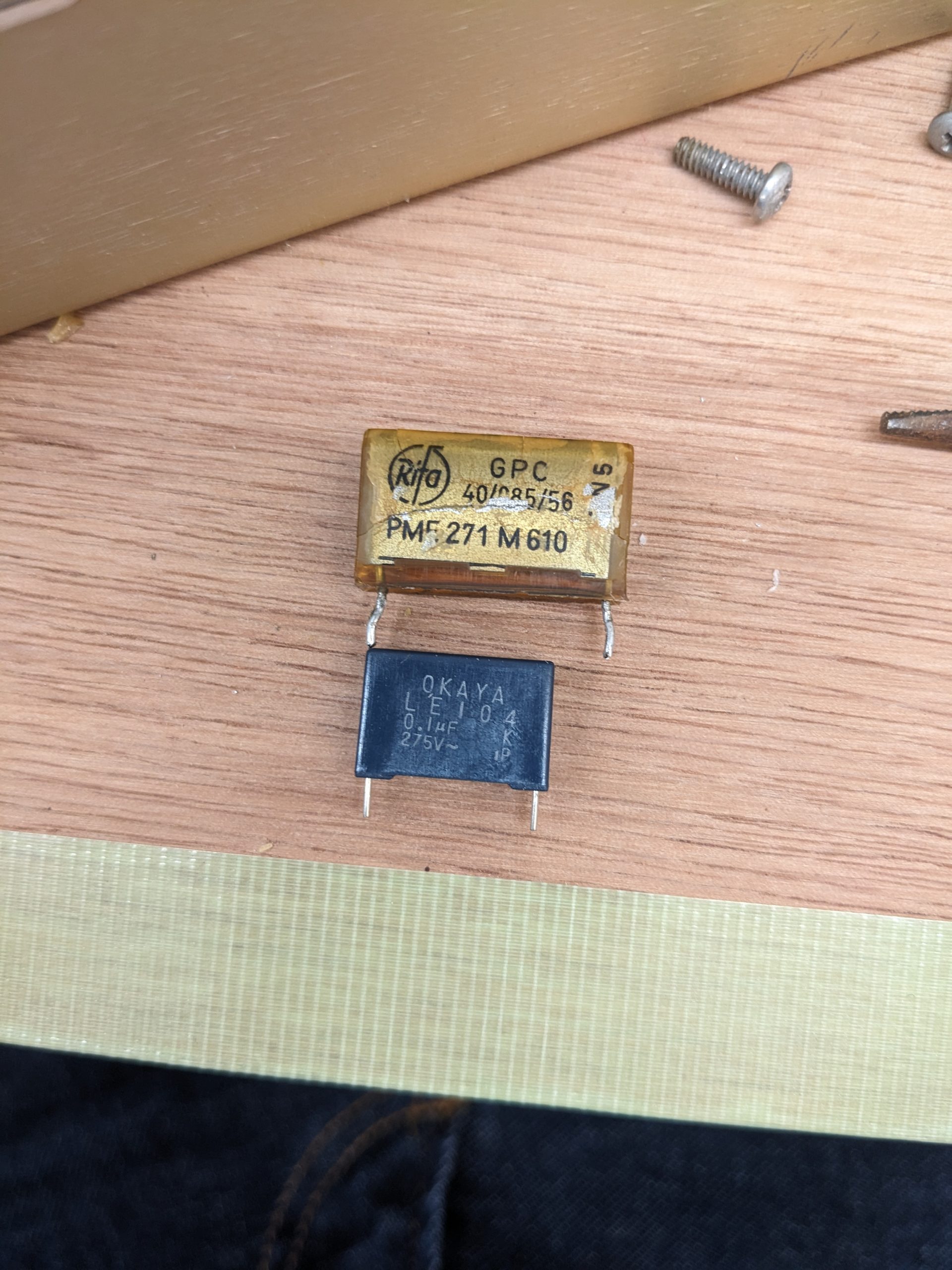
From the symptoms I’d correctly assumed that the owner had witnessed a RIFA capacitor explosion, so I came prepared by buying some replacement caps! I’d expected to have to bodge them due their size difference, but to my surprise, the PSU board had three holes for the noise suppression caps. The RIFA cap was using the outer holes (“holes 1 and 3”), and my smaller cap fit perfectly into holes 2 and 3! Cool beans.
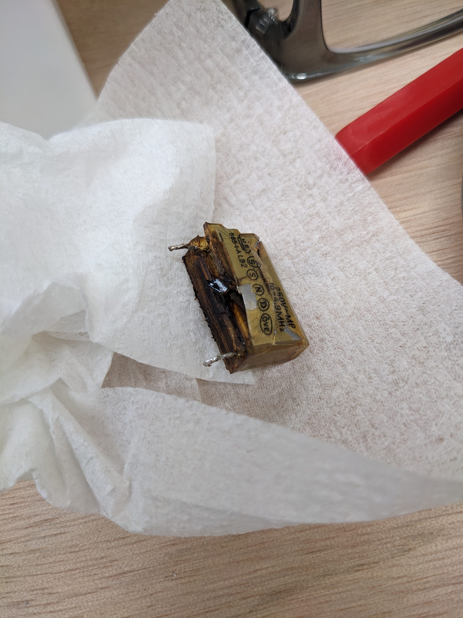
Original RIFA cap (pin spacing of around 2 cm I believe) and replacement (1.5 cm). (The replacement cap has its X2-certification on the other side.)
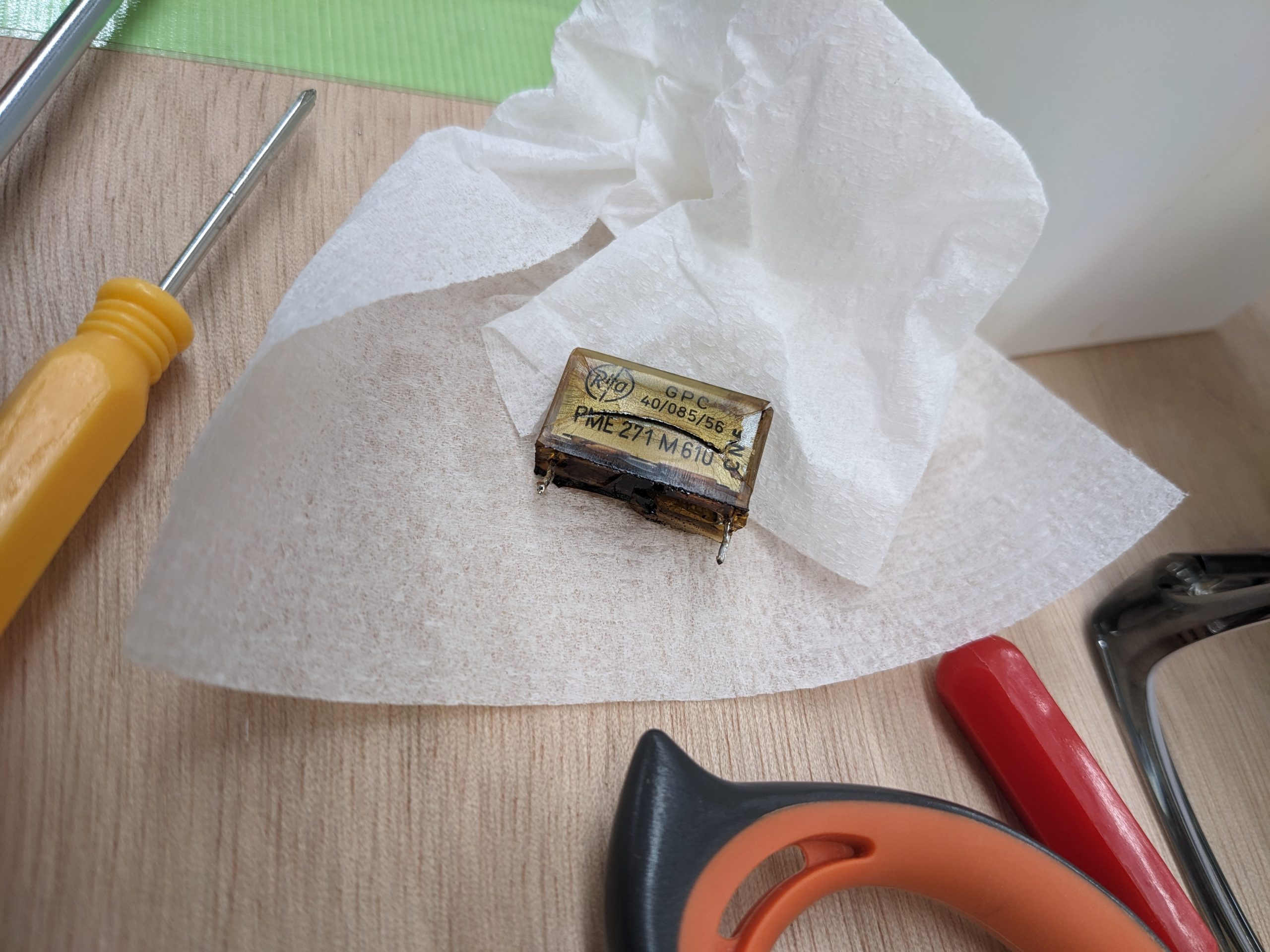
The PSU had two RIFA caps. The one pictured above is “intact”, though it has a huge crack in its plastic case. Here are the pictures that we’ve all been waiting for, the exploded cap:
The ejected brown juice wasn’t too bad and cleaned up quite nicely.
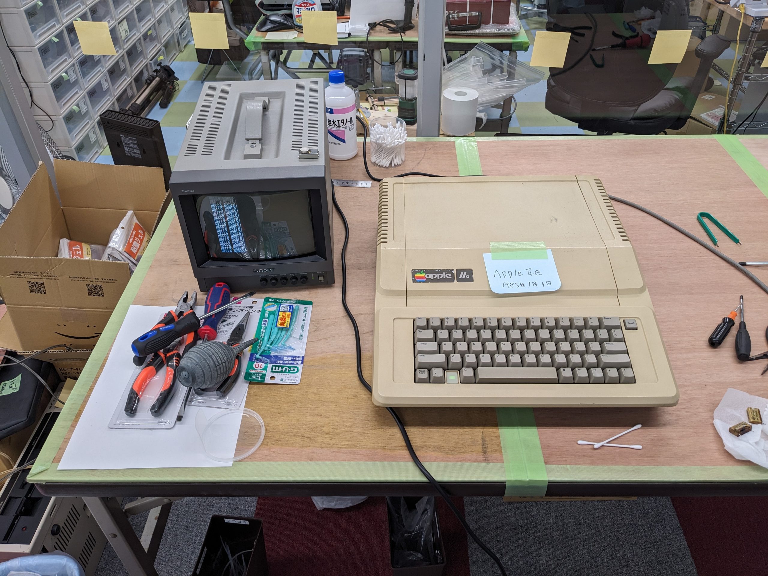
Here is the computer put back together again, already performing advanced calculations.
The end.
Edit 2024-07-11: one more, an Apple II Plus
This guy’s power supply was riveted. What the actual? I think the screws used were some tamper-proof kind, too. The rivets were drilled out and the screws still wouldn’t come out, beyond a millimeter or so. So the screws were drilled out too. It was a bit of a nightmare. The label on the power supply said Astec AA1040. There were no RIFA caps in it.
A while ago an acquaintance asked me to build a power supply for his replica Apple 1 board. He had all parts on hand (in fact, they were the exact parts mentioned in the Apple 1 documentation and schematics, Stancor P-380 and Stancor P-8667). My acquaintance probably knows a lot more than me, so I basically just did what he asked: I drilled holes into a sufficiently nice piece of wood from the 100-yen shop, soldered connections to the transformers (I believe they were probably salvaged, but luckily still had wires attached), added a fuse, soldered an AC cable into the mix, and soldered the Apple 1 power connector. Doing all this took between 4 and 8 hours, I don’t really remember. Here’s a picture of the assembled power supply.
With multimeters hooked up to each of the voltage rails (-12V, -5V, 5V, 12V), I hid behind a big rock and pushed down on an ACME plunger detonator. The explosion… didn’t take place, and the voltages were all good. Phew! Next I hooked up a period-correct monochrome CRT, and saw an image! A very jumpy image. It was possible to adjust HSYNC on the back of the CRT, which stabilized the image, but it still didn’t look correct. Pressing RESET or any other key on the keyboard didn’t do anything.
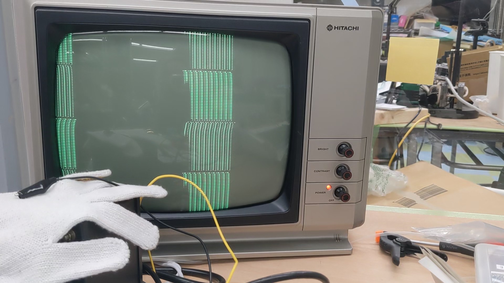
Stable (i.e., not rolling) but incorrect image
(Note on fuses: my fuse is on the primary side, mains voltage here is about 100V. I blew a 0.3A fuse on power up, then a 0.5A fuse on power up, and am currently using a 2.5A fuse. Maybe I’ll try 1.0A or 1.5A. Or maybe I should go and look at slow blow fuses.)
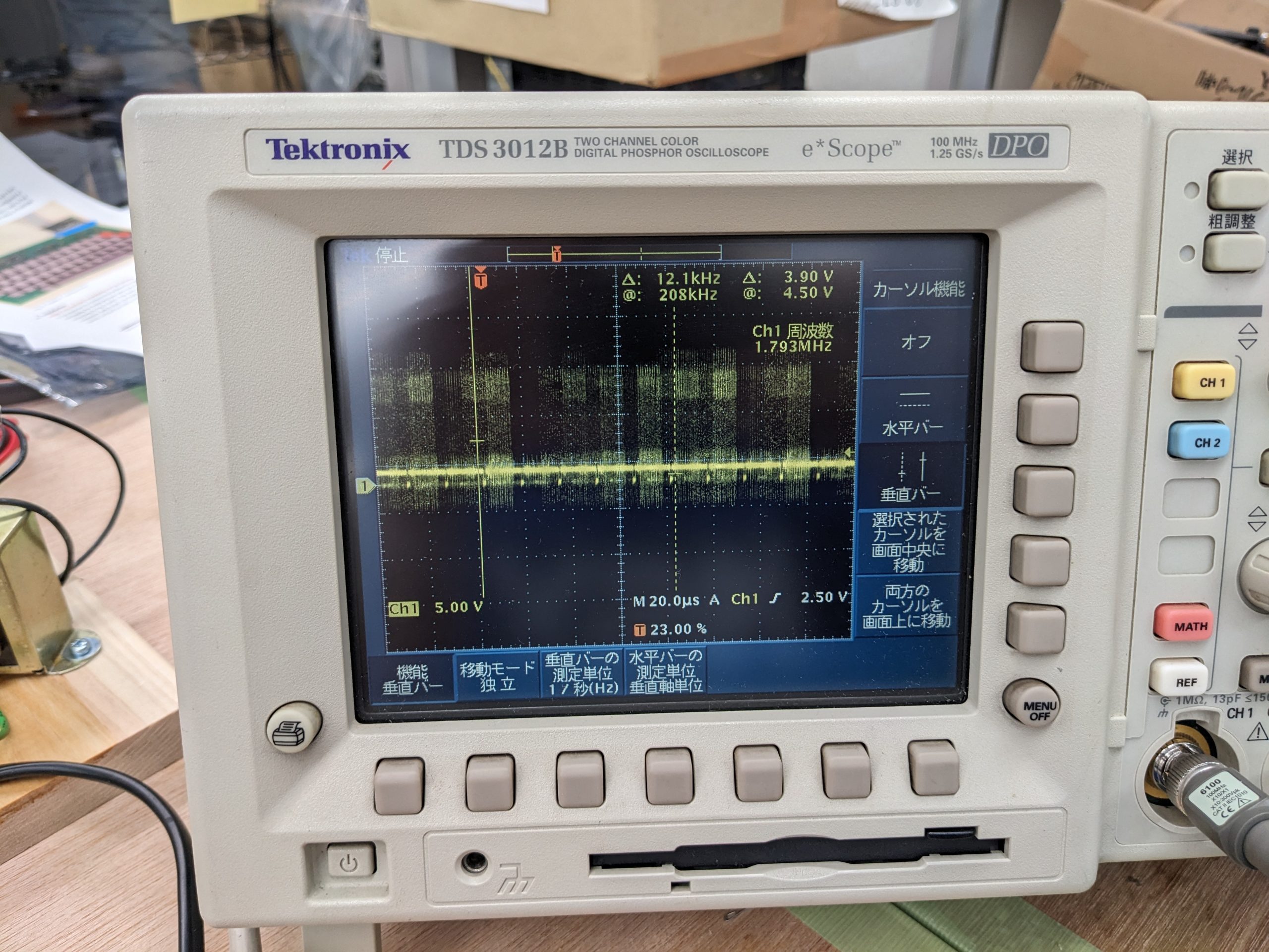
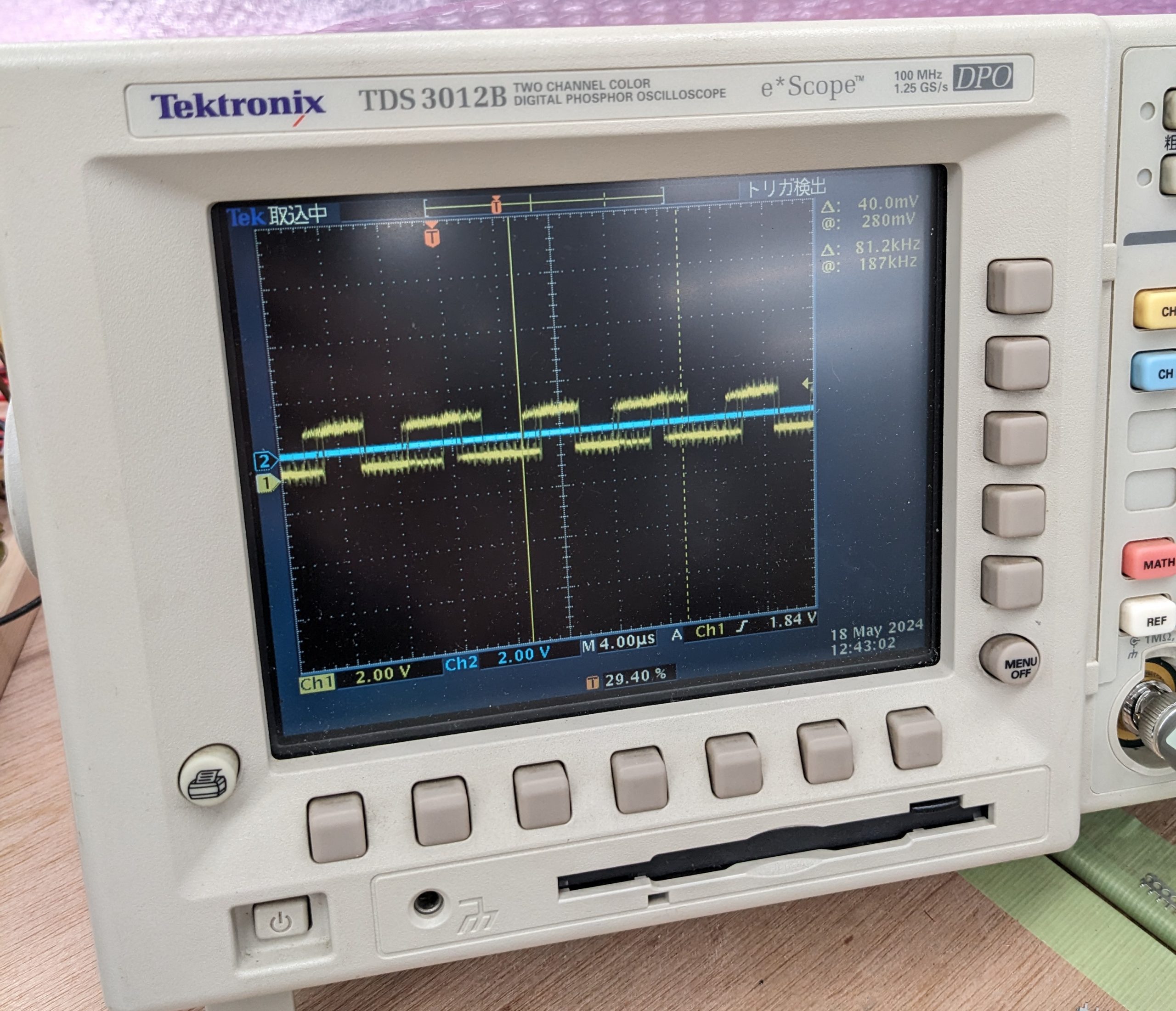
Before studying the schematics, I fired up an oscilloscope and had a look at the frequencies of the video signal. Here’s what I found:
Those small yellow blobs in regularly-spaced intervals close to the center line are the wannabe horizontal blank periods. They are supposed to have a frequency of 15.something KHz. In the above picture, I moved the oscilloscope’s vertical cursors further apart such that I get a frequency somewhat close to 15 (12.1 KHz), and as you can see we get 6 horizontal blanks in that period! This means the video signal is much too fast. I also looked for the vertical blank. It’s supposed to be 60 Hz and measured as 243 Hz. (Probably actually 240 Hz.) (At this point it’s worth worrying that we might be overclocking the CPU as well, but that wasn’t the case, it was running at a safe speed.)
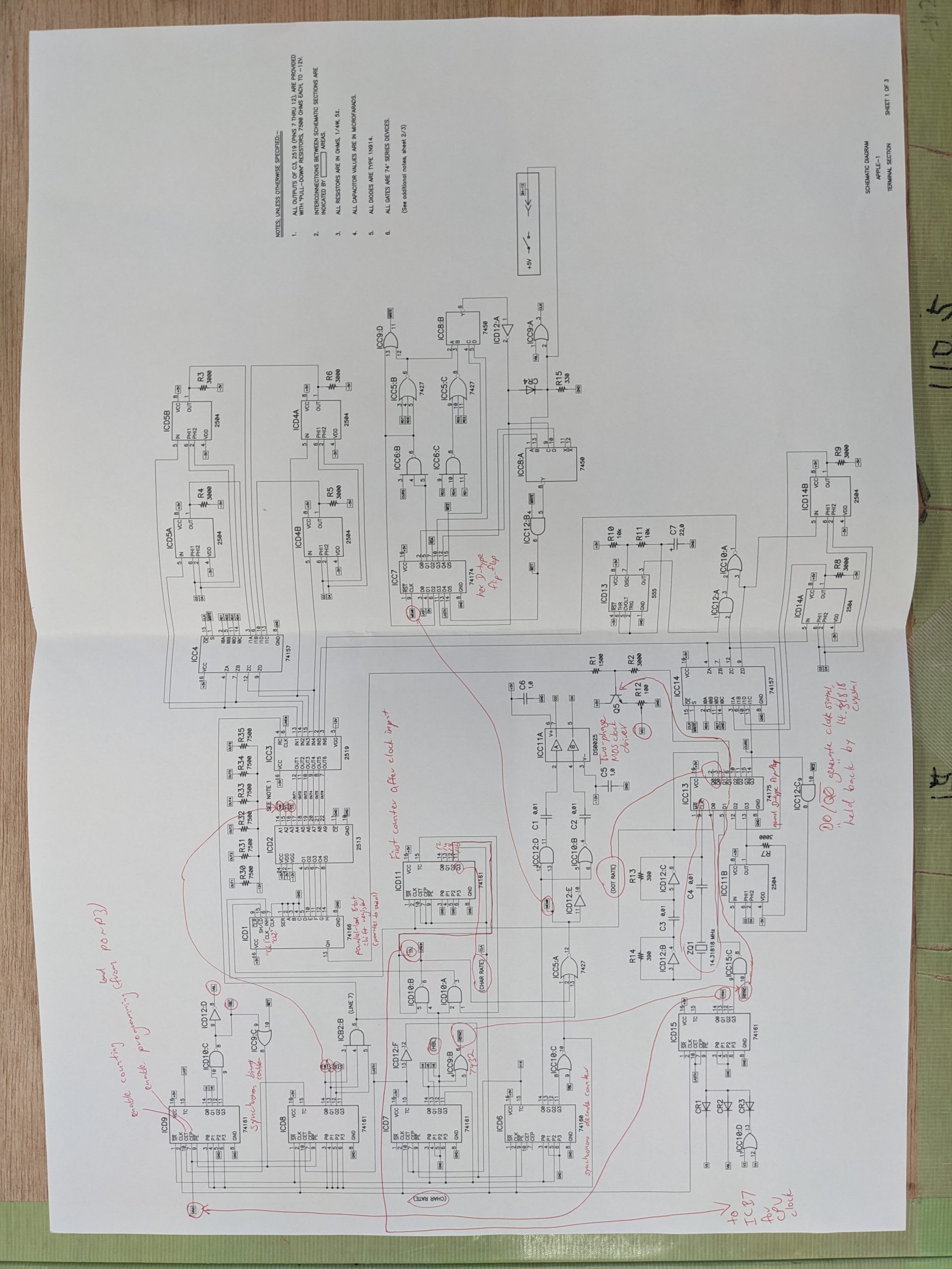
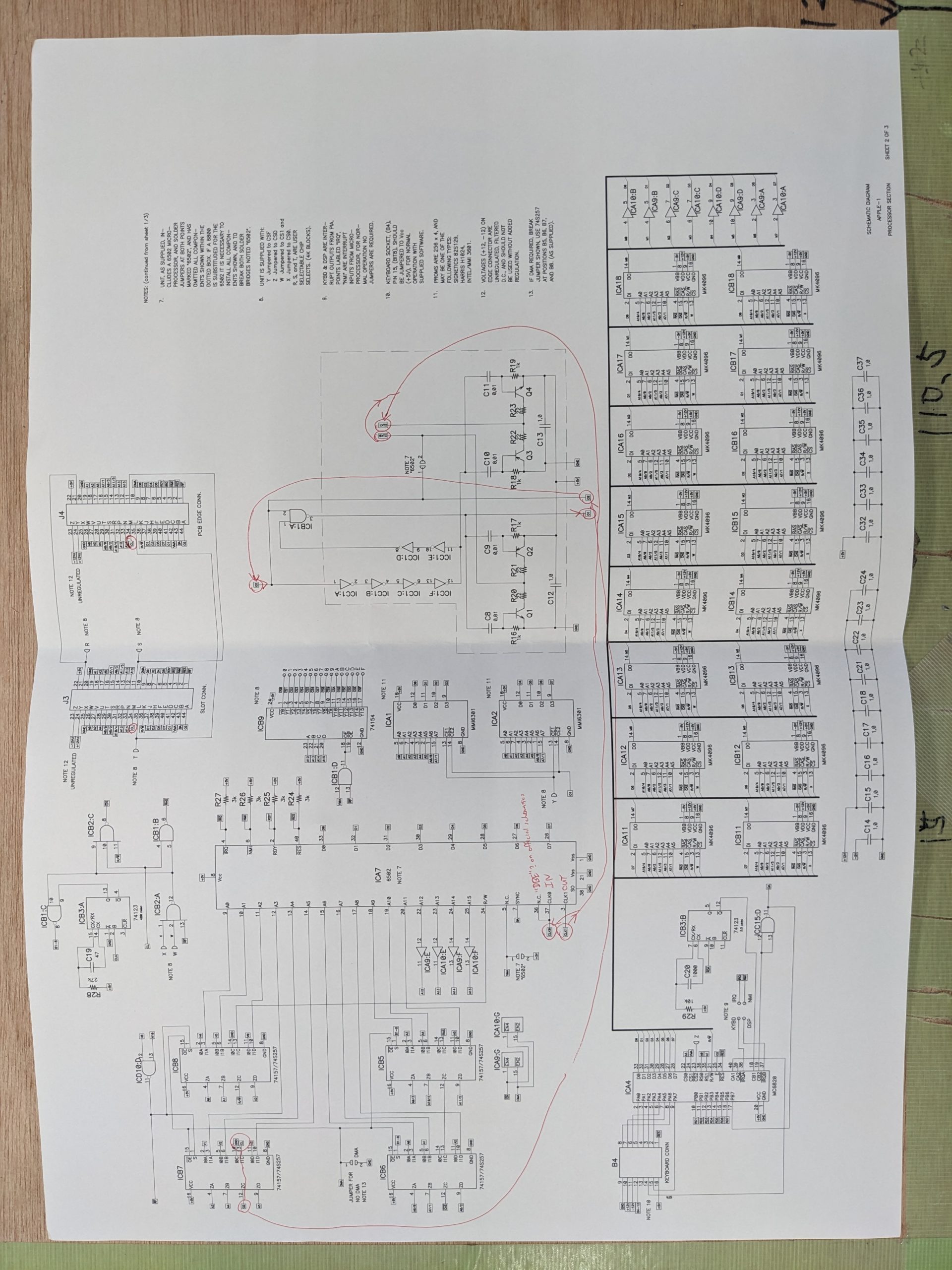
At this point it was time to print out the schematics and study them. Here’s a picture of my annotated Apple 1 schematics that I used to debug the problem:
Teletype section (Note that I cannot guarantee that all my annotations are 100% correct.)CPU section (nothing much annotated here)
Some repair guidelines
There isn’t all that much repair information on the Apple 1, but it’s not too complicated. The computer is basically two devices, a teletype that generates video, and a “computer” section that has the CPU, ROM, and memory. The two devices are linked through an MC6820 chip. There’s one more link; we also get the clock signal for the CPU from teletype section.
One more thing: when you turn on the Apple 1, the CPU isn’t live yet, because there is no reset circuit! (You have to reset the CPU manually using a special key on the keyboard.) So anything that looks too garbage-y right on power up isn’t likely to have much to do with the CPU.
Repair
After studying the schematics, I fired up an oscilloscope and traced the oscillator’s output, through the flip-flop, through various counter stages. At this point, a little luck, or a different strategy, would have helped me find the problem rather quickly, but it took at least an hour (probably more) of poking around until I found something obviously out of the ordinary: the “TC” output of the 74160 decade-counter IC was very low. Man, if it had been a Q output I’d have found it in minutes, heh.
74160’s TC output
I removed other chips the TC signal goes to, removed the 74160, checked for shorts to adjacent pins on the board, but couldn’t find anything. Which means the bad signal is produced by the 74160. Perhaps it would work with a slightly higher voltage, so maybe we’ll keep it. So we decided to see if we could get some replacement 74160 ICs (none of that Low-Power Schottky rubbish), and fortunately someone was selling them on Yahoo Auctions! We procured a few and the replacement 74160 made the problem go away!
(74LS160s or even modern HCTs/ACTs/whathaveyous would have likely worked too, but this replica board is proudly populated with original non-LS chips from mostly the 1970s. It’s all fun and games until they say good-bye!)
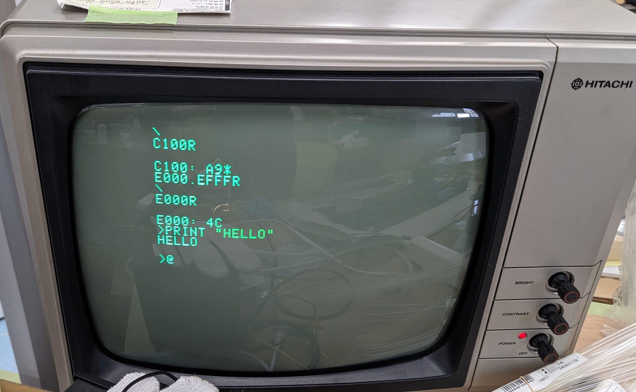
There were no more defects and we were able to boot into Wozmon and load BASIC from tape.
How to boot into BASIC
After powering up, clear the screen and reset the CPU using the dedicated keys. You should get a ‘\’ prompt. Type C100R and enter. This runs the cassette firmware. You should get “C100: A9*”. Then type in E000.EFFFR and at the same time you press enter, start playing the tape. (This loads the BASIC interpreter into memory at 0xE000 to 0xEFFF.) When the audio stops and you get ‘\’ you can start the BASIC interpreter by typing E000R and enter. The BASIC prompt is ‘>’.
The acrylic case
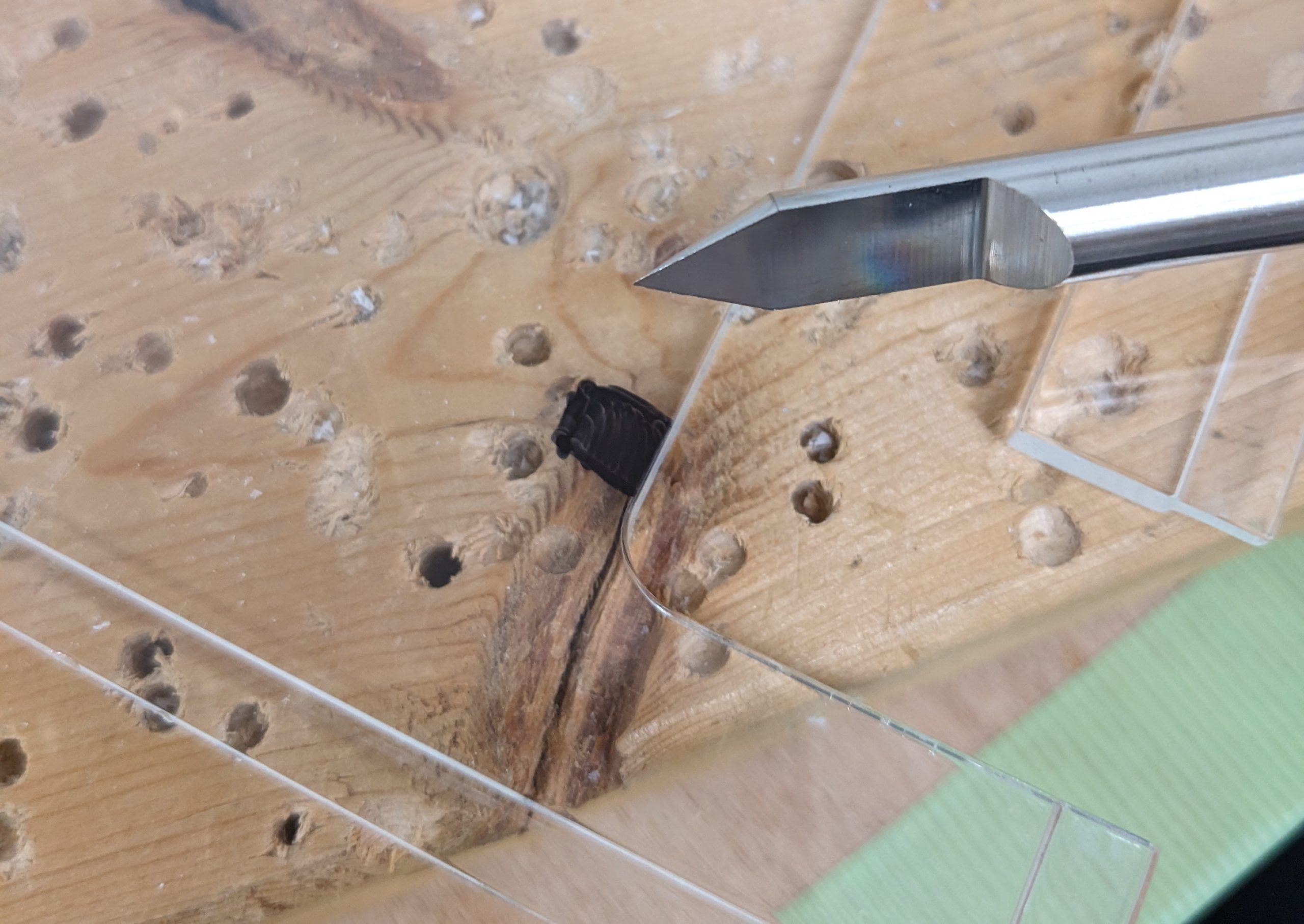
For some reason, the acrylic case that was purchased to put this system into didn’t have the screw holes in the right location, so I had the pleasure of adding more screw holes into the case. (Not just that, the lid needed some trimming in order to fit the cassette board, and we also decided to mod the air inlet/outlet a bit.) And though I didn’t have any experience drilling holes into acrylic (or even a lot of experience drilling anything, really), it actually went really well, using these drill bits specially made for use with acrylic: https://www.amazon.co.jp/dp/B00A630ZRE: Acrysunday アクリル板専用ビット.
It all worked out, mostly. When I did the four holes for the fan I unfortunately didn’t take into account that when screwing the nuts onto the bolts, the nut will obviously add a millimeter (or so) of height vs. just a naked bolt. (The case isn’t that high, so I just had a couple of millimeters I could move the holes up or down.) Putting the nuts on the two top bolts will prevent the lid (the one pictured above) from fitting properly, it would rest on the nuts instead of on the bottom case.
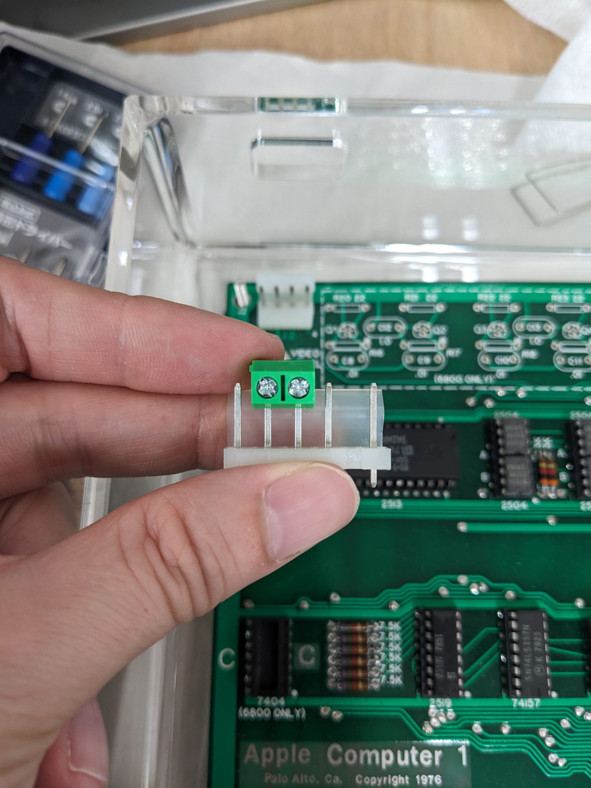
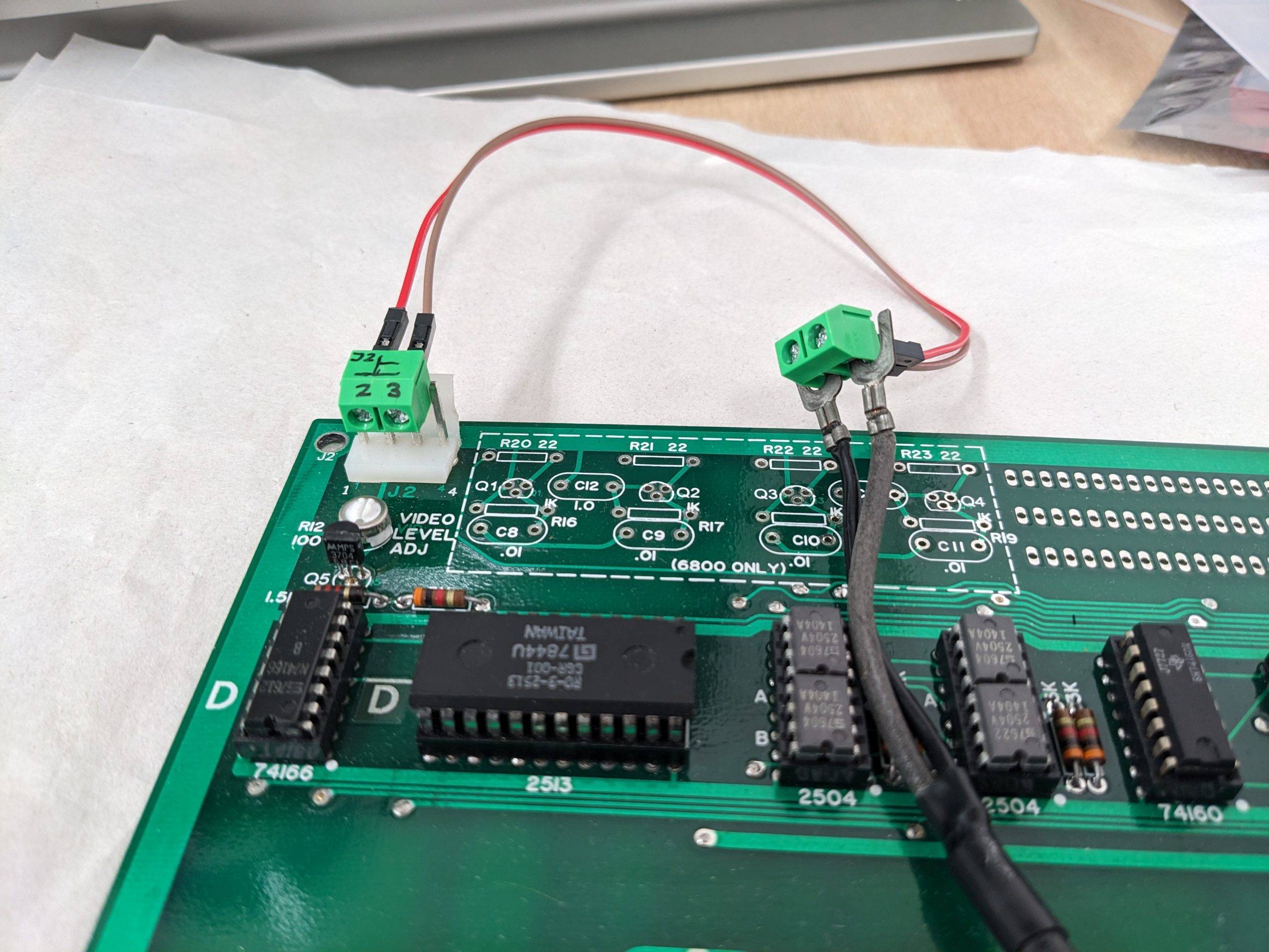
We added some heatsinks on all of the counter ICs, all of which were running rather hot (about 65 degrees after 10 minutes of operation), a powerful fan to blow air on the main voltage regulator (which sucks air through a filter so we don’t end up with a bunch of dust inside), and made a make-shift connector for the video port (J2).
Makeshift video connector using screw terminals: general ideaMakeshift video connector: placed on J2 and connected to TV input
I’ve been developing software for the ESP32 and ESP32S3 “professionally” for about one year now. I still like the Raspberry Pi Pico better, but the ESP32 line of microcontrollers is cool too. And if you need wireless and don’t really care too much about power consumption, the ESP32 (or -S3 or what have you) is a nice thing to have around.
The examples in IDF (the name of the ESP32 SDK) are really great, and you can do a bunch of stuff just by taking an example and changing a couple lines.
I’m a huge fan of the Raspberry Pi Pico’s PIO, and the ESP32 has something that is slightly similar, as-in “programmable IO”. It’s called “RMT”, and in examples/peripherals/rmt, we have a few examples that make use of this bit of silicon. The examples/peripherals/rmt/ir_nec_transceiver example is the one we look at in this article.
Basically, all you have to do is flash this to your dev board and connect an IR receiver module’s output pin to GPIO19 (and its VCC and GND to VCC and GND. Be sure to hook it up to 3.3V, not 5V.) If you want to do what this example is supposed to do (output the same signal back through an infrared LED on GPIO18), feel free. But if you just want to sniff codes, leave the infrared LED disconnected and look at the UART output.
Note that the output of the IR receiver is expected to be inverted compared to the actually sent signal. I think most IR receivers invert the signal, so you’ll most likely be fine.
Build steps
If your dev board isn’t a standard ESP32, but e.g. an ESP32S3, you first have to do:
idf.py set-target esp32s3
Then you do:
idf.py flash monitor
This will build the example, flash it to the dev board, and start a monitor.
Then you’ll see a bunch of output like this:
NEC frame start---
{0:218},{1:0}
---NEC frame end: Unknown NEC frame
But if you press a key on a remote control, you may see something like this:
And there you have the address and the command! Note that by default, extended NEC codes are allowed. (However, the remote control I used here generates a non-extended NEC code, where the second byte in the address (and command) is the first byte but inverted. I.e., 0xFF == ^0x00, 0xCE == ^0x31.)
And that’s all! If you output this using an IR LED (make sure you use a resistor), you will be able to control the device in question using your microcontroller. Note that you will probably have to move the LED rather close to the device you’re trying to control (depending on your resistor value). Note that you shouldn’t really exceed 30 mA per GPIO. I understand that most IR LEDs are good up to 100 mA, but the ESP32’s GPIO pins aren’t. You’ll need to amplify the signal if you want to go higher than 30 mA.
Sniffing IR (NEC) codes on the Raspberry Pi Pico
The Pico has a very similar demo, pico-examples/pio/ir_nec/ir_loopback/ir_loopback.c. If all you want to do is sniffing, it may work a little nicer if you comment out the sending stuff (everything from “// create a 32-bit frame and add it to the transmit FIFO” to “sleep_ms(100);”), as well as the sleep_ms(900) at the bottom. (Otherwise you’ll have to wait a little bit until your IR code shows up.) Also, it won’t do extended NEC codes. You’d have to modify nec_receive.c a little bit.