I recently stumbled upon some source code I wrote when I was 18! I was very much into graphical effects back then, and all of that code targeted SVGAlib, which isn’t really a thing anymore. So I teamed up with ChatGPT to write a thin translation layer to SDL, and I believe I got all of my code to work! Mind you, I didn’t use any advanced features. Just setting modes, setting pixels, and setting the palette.
I (and/or ChatGPT) didn’t implement anything beyond what I needed. Therefore, only the following modes are supported:
G800x600x256 (palette-based) G800x600x64K (16-bit color depth RGB) G1024x768x16M (24-bit color depth RGB)
And that’s it, really. Also, the palette mode is implemented in software.
Does it just work without modifying the source at all? No, not quite. In SVGAlib, all graphics calls are effective immediately, and you would call e.g. sleep() or usleep() to slow down animations. In SDL2, you tell the library that it’s okay to render a frame now. Also, if you modify the palette when you already had something onscreen, and you want the existing pixels to reflect the changes to the palette (usually the case), you need to call a function that redraws the whole screen.
What this means: 1) add a call to vga_waitretrace() before every sleep or usleep(), 2) add a call to redraw_after_palette_update() after you’re done modifying the palette. So let’s say if you have a program like this:
#include <vga.h>

int main()
{
  int x, y;
  vga_init();
  vga_setmode(G800x600x256);

  for (y = 0; y <= 599; y++) {
    for (x = 0; x <= 799; x++) {
      vga_setcolor(x ^ y);
      vga_drawpixel(x, y);
    }
  }
  sleep(5);
}
You modify it like this:
#include <vga.h>

int main()
{
  int x, y;
  vga_init();
  vga_setmode(G800x600x256);

  for (y = 0; y <= 599; y++) {
    for (x = 0; x <= 799; x++) {
      vga_setcolor(x ^ y);
      vga_drawpixel(x, y);
    }
  }
  vga_waitretrace();
  sleep(5);
}
And you put the vga.h shim into your current directory and compile like this:
We honestly didn’t really do much in part 1 beyond cleaning and getting the thing powered; fixed some keys and the source of the constant power consumption in part 2, and this is part 3, which is just a quickie really.
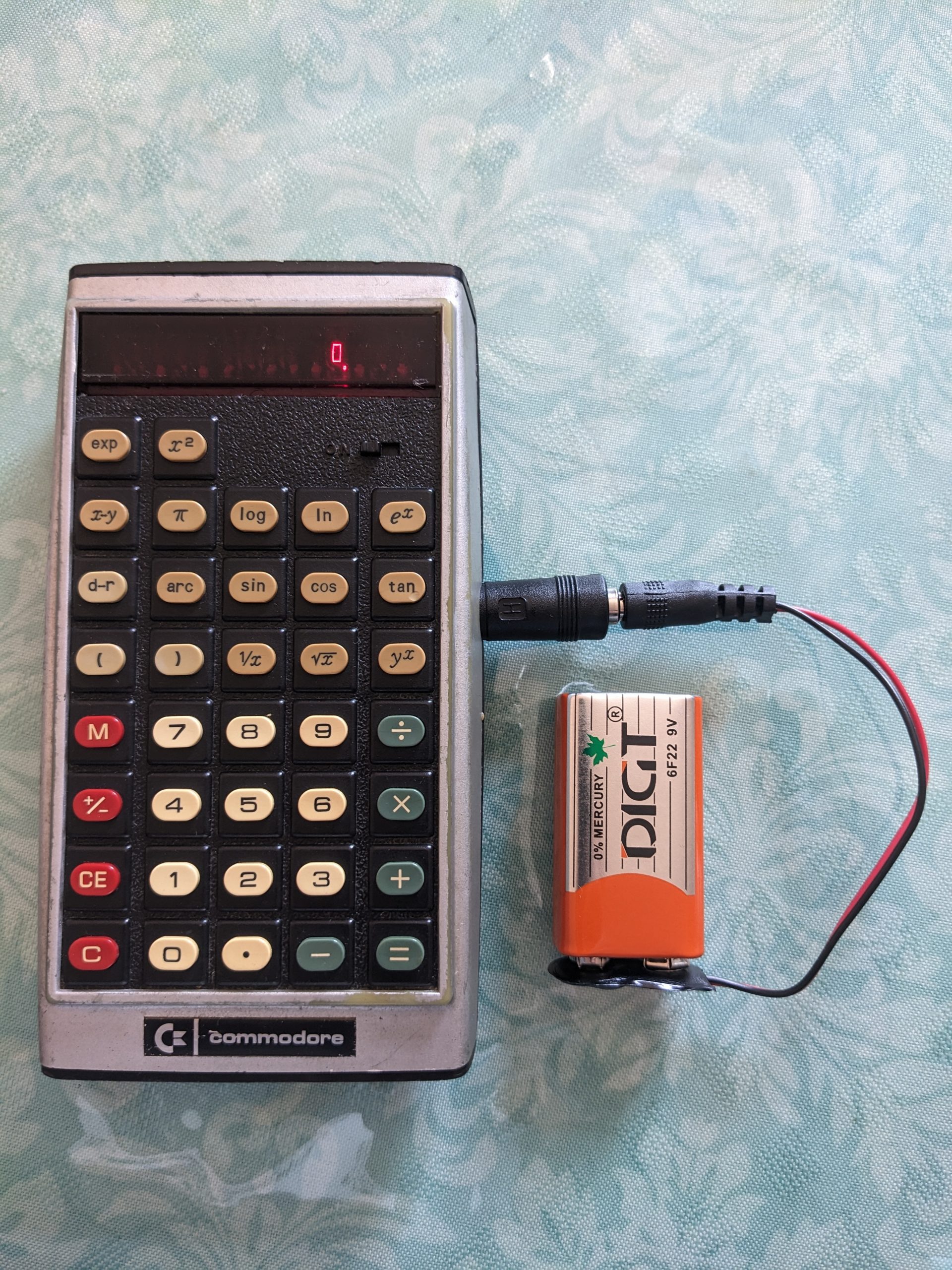
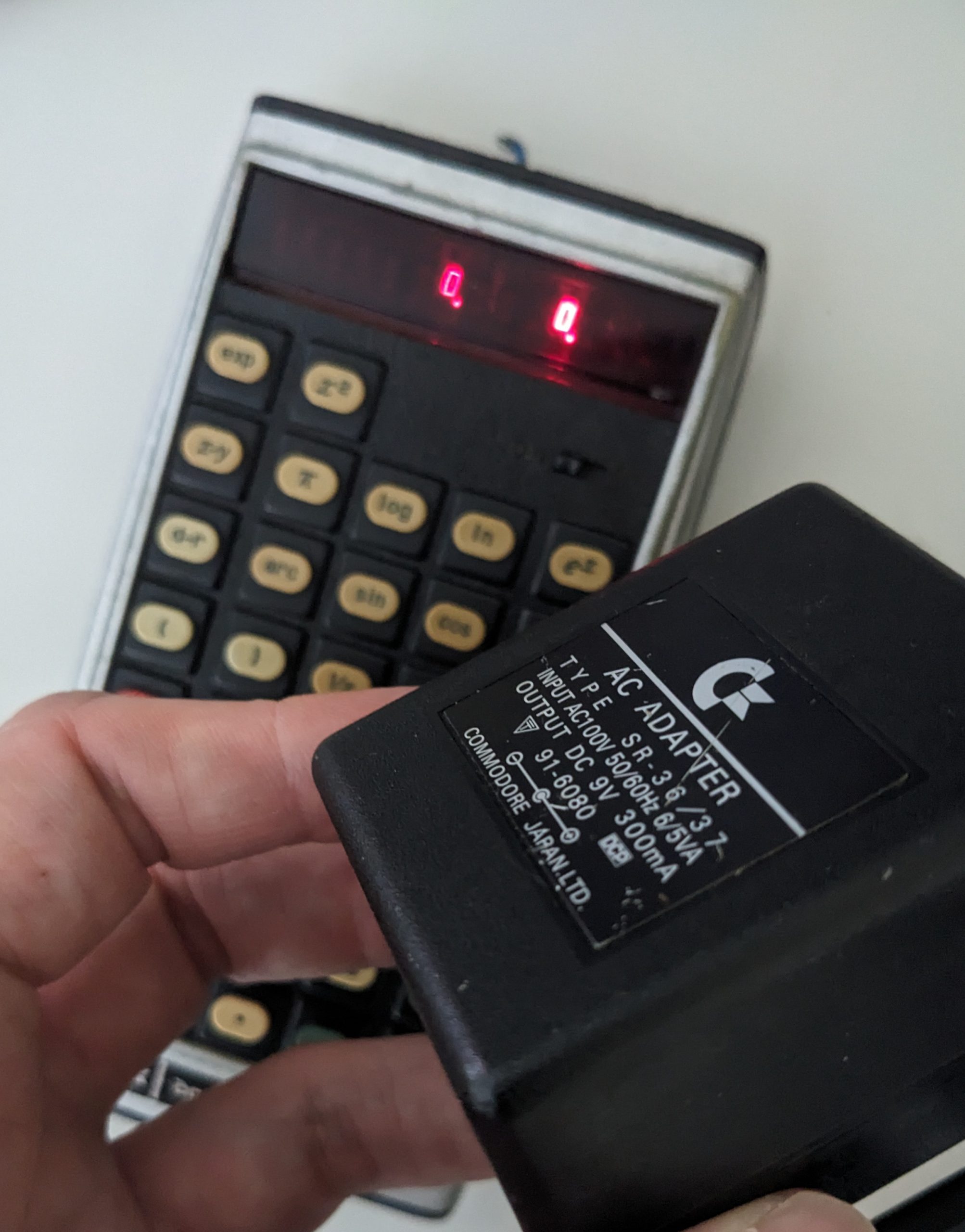
The calculator works wonderfully, it’s just annoying to have to use it with wall power. In comes a 9V battery! And a 9V snap connector to DC plug adapter that I found at a local shop for just 100 yen!
That’s honestly good enough for me. Maybe I’ll solder on a proper 3.5 mm connector instead of using the DC to 3.5 mm adapter at some point.
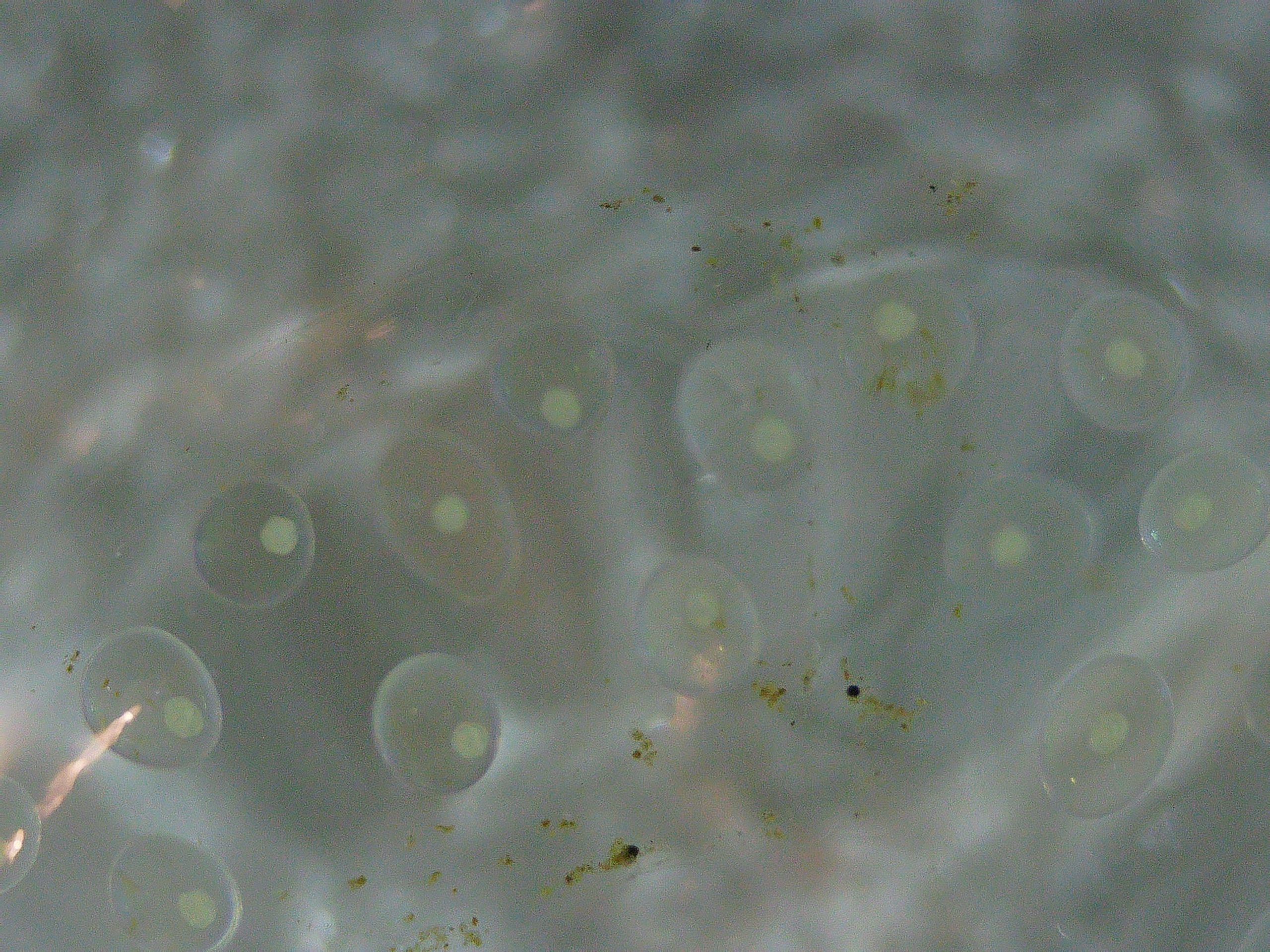
The single Radix auricularia japonica snail in my tank decided to reproduce, most likely all on its own. I believe it must have arrived on my Cabomba as an egg (bought about 6 weeks ago), but it’s also possible it actually arrived as a micro-snail and mated with another micro-snail… Now having actually seen how tiny freshly hatched micro-snails are, I don’t think it’s impossible it arrived as one. Below is a look at one of the newly hatched ones (there are over 10 in total) through a microscope. I also included a picture of its eggs. They are embedded in a jelly-like substance, and hidden inside the Cabomba.
カワ(・∀・)イイ!!Same magnification as above. (Different resolution though, so only the same if viewed resized to the same area.) I don’t know if these eggs are fertilized or not. 同じ倍率で卵の写真も撮ってみた。(しかし解像度が違うのでサイズを合わせた場合に限り同じ倍率。なはず。)受精済みなのかどうかわからない。
In my previous post from over 1 year ago, I noted that there was 1 W of power consumption even when my Commodore SR-37 calculator was switched off. In this post, we are going to investigate and tackle this problem, and fix a key that sort of worked when I got the calculator, but in the meantime stopped working completely. I also fixed the power supply (replaced the very worn cable) that came with the calculator, but for reasons I will explain later, we unfortunately won’t be able to use it with this device.
The power consumption issue
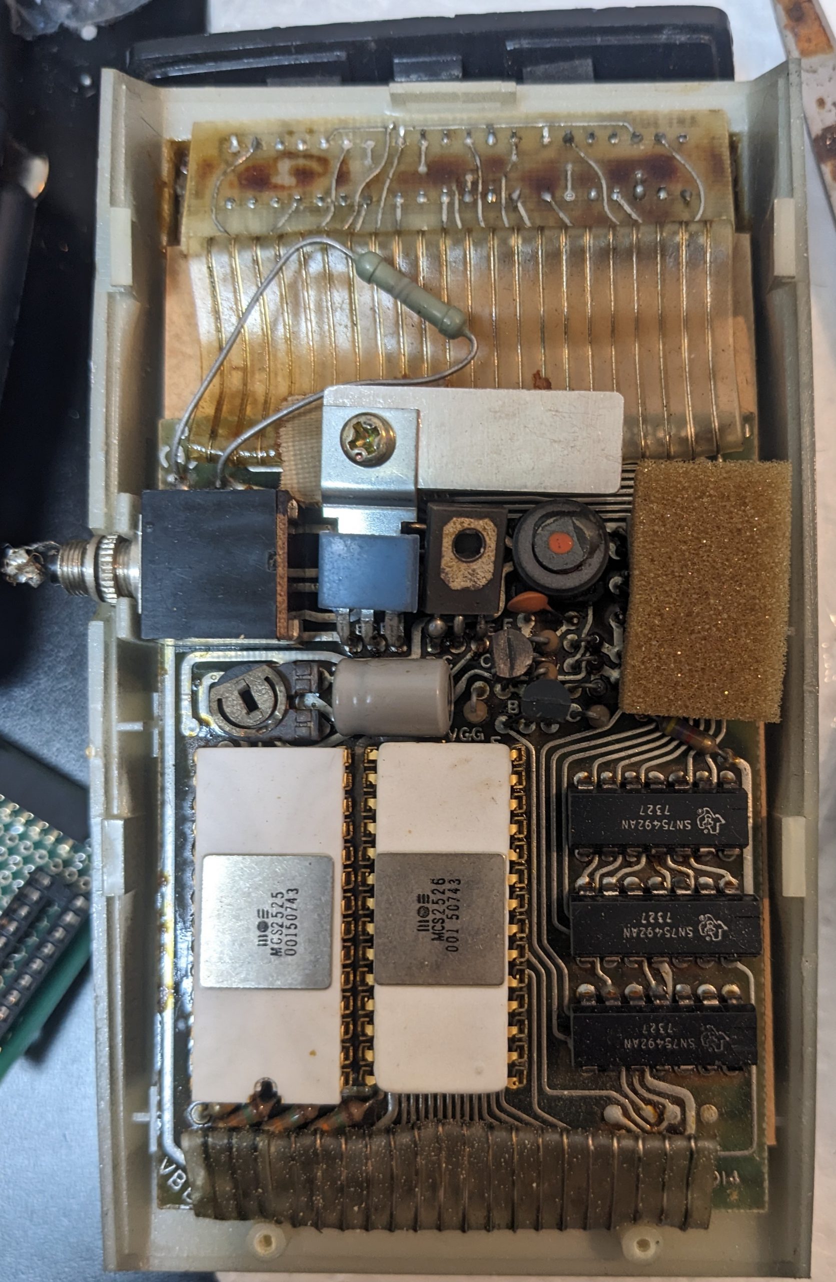
1 W of power consumption isn’t easy to hide in a confined space, because most of the time it’s converted to 1 W of heat. Let’s take a look with the thermal camera. Here’s a picture of the insides, again:
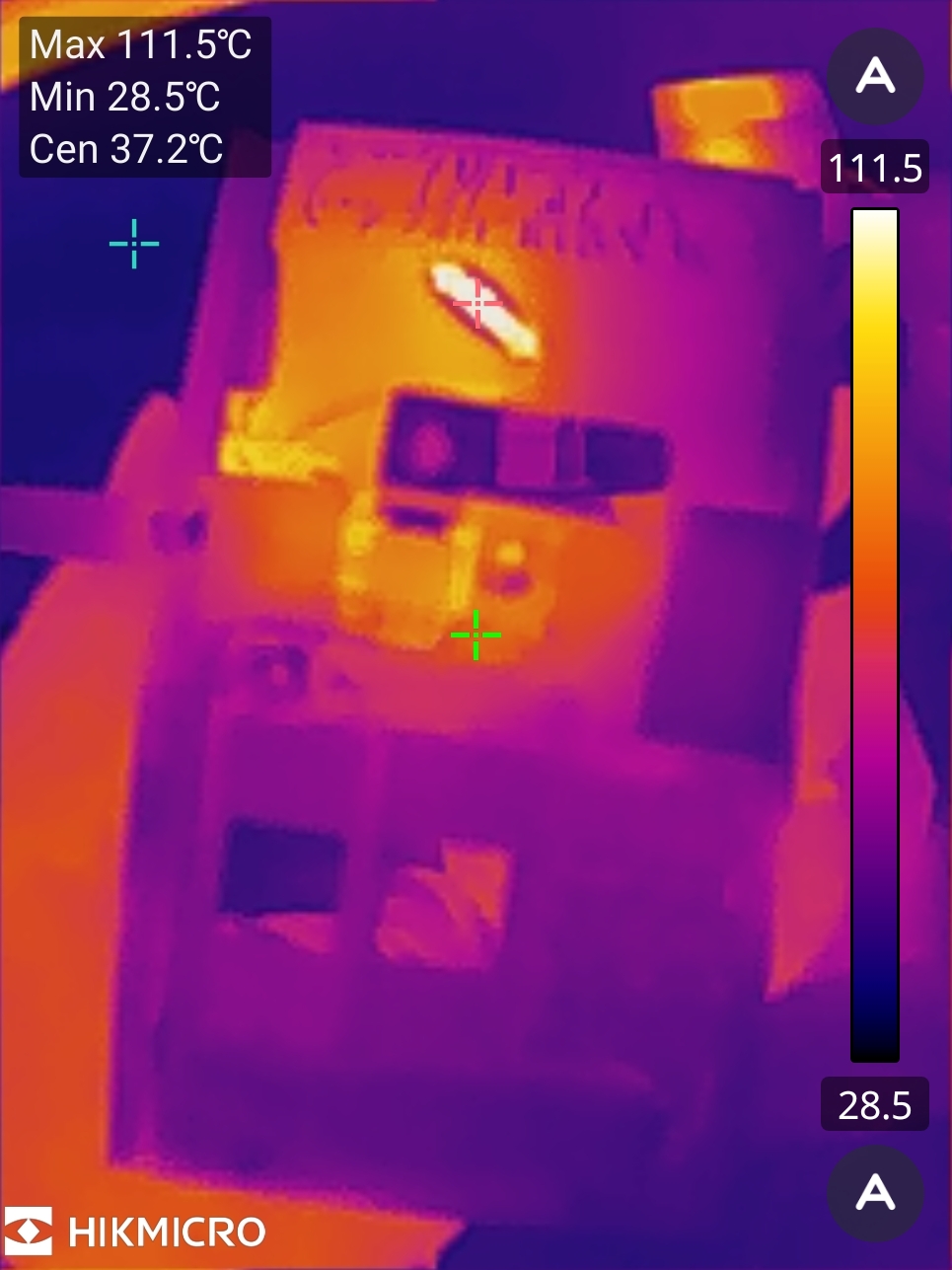
And here’s what’s getting hot:
111.5 °C, 232.7 °F
Okay, so it’s just that added-after-the-fact-looking weird-ass resistor sitting between + and -! It’s a 100 ohm resistor, the power supply is like 9V or maybe 10V. So that’s 1 W accounted for! There are no signs of rework, and the resistor looks quite antique, so I’m going to guess it was added at the factory. Why?
This resistor is sitting between positive and ground and effectively just puts a load on the power supply. This load will drop the power supply’s voltage a little bit. As the power supply is an unregulated linear power supply, the unloaded voltage will be 12V or so. Applying a load will drop this to 9V or less.
The power supply’s voltage is applied to the SN75492 LED display driver chips. These are rated for 10V. Do you see the problem? Without enough load, our power supply will supply a larger voltage to these chips. It would be a little bit cleverer if they had put the resistor somewhere that is interrupted by the power switch, but as they say, “why clever if dumb OK and just 111°C”?
By the way, it’s possible that this calculator sometimes(?) came with rechargeable batteries, and that the recharging circuit adds enough load to make the power supply suitable for this calculator. I don’t know if this is the budget version without the rechargeable batteries, or if they deteriorated and were removed somewhat professionally. The backside of the calculator has some basic instructions on it, and mentions charging:
Turn machine off when not in use. It is recommended that the unit be charged over night to assure maximum DC performance.
Anyway, I removed the resistor, and measured the voltage on the SN75492 chips. It was 9.4V, so we should be good, no? Well, maybe these chips came from a batch that was less tolerant of voltages closer to 10V, cause the display is “doubled”. When you display more (by e.g. pressing 888888) the voltage drops some more, and the problem disappears. When you use a different power supply that supplies a little less voltage, the problem also disappears.
The pictured power supply is the one that came with the calculator. (The cable had deteriorated, so I’d replaced it.) Having repaired this thing, I was looking forward to using it. So I’d thought of building a small modular thing I could between it and the calculator to drop the voltage a little bit, perhaps using a four diodes in series, which would waste less power than a resistor. Unfortunately I made a couple soldering mishaps and ended up trashing that project, oops. At least the power supply is still original and usable with other old devices, e.g. my ZX80 replica!
So, let’s see what else we can do? We tried 7V. Works. Non-standard, inconvenient. What about 5V? Turns out that 5V works!
… Or does it?
Things that are unusual when running the calculator @ 5V
First of all, we need to define what 5V means. Have you ever measured the voltage coming out of a USB-A power supply? Most often, it’s 5.1V. Sometimes, it’s 5.2V. It can be higher, but usually doesn’t get higher than 5.5V. According to the USB specs, however, it’s 5V +- 5%, so 4.75V to 5.25V.
This calculator will run at any of these voltages. However, the lower the voltage, the darker the LED display. No problem. Anything else?
Well, would you believe me if I told you that it starts making “mistakes” when the voltage is too low? Specifically, division appears to go wonky at lower values of 5V. E.g., 8/4 is no longer 2:
8/4 = 2. 8/4 = 2. 8/4 = … 0.3003003. Note that the power supply’s display isn’t 100% accurate and is usually off by 0.2V.
Anyway, I’ll run it at 5V because I have plenty of power supplies that output various kinds of 5V.
Fixing the ‘1’ key
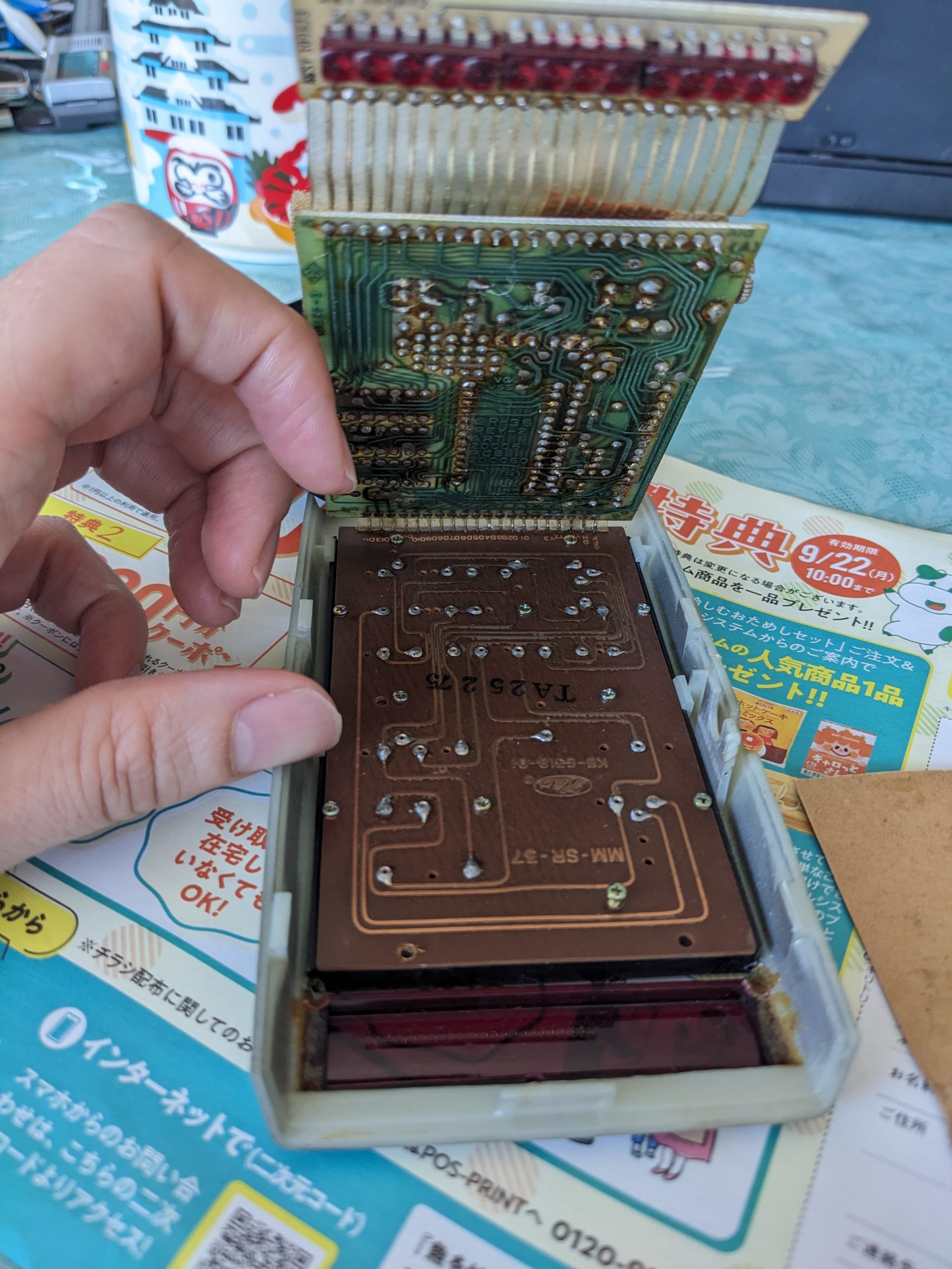
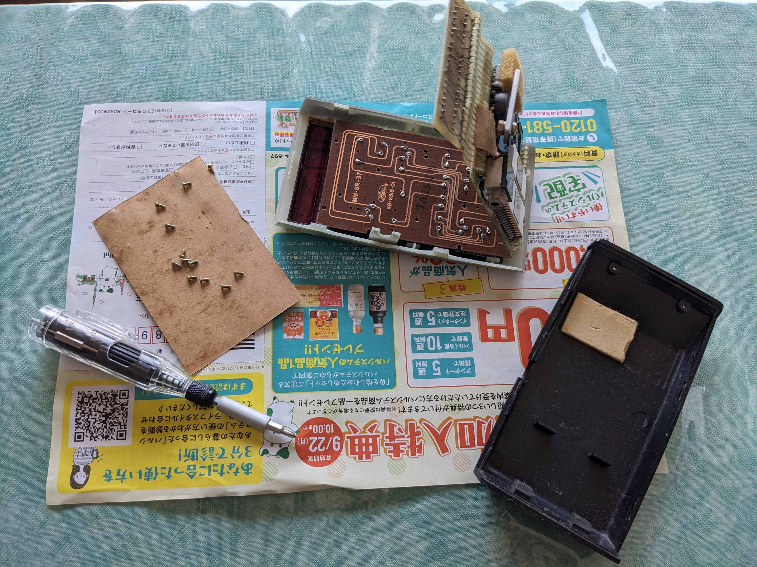
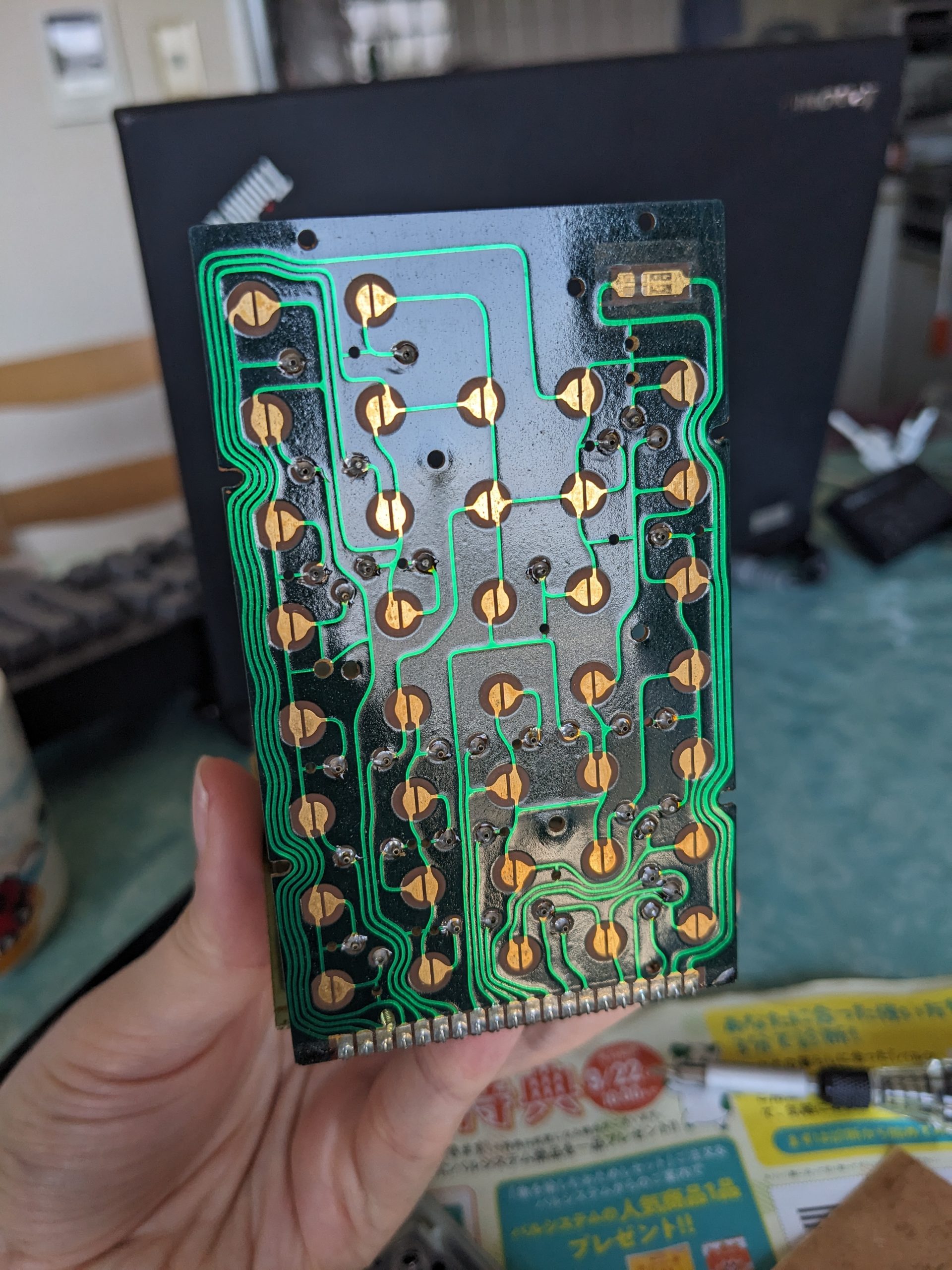
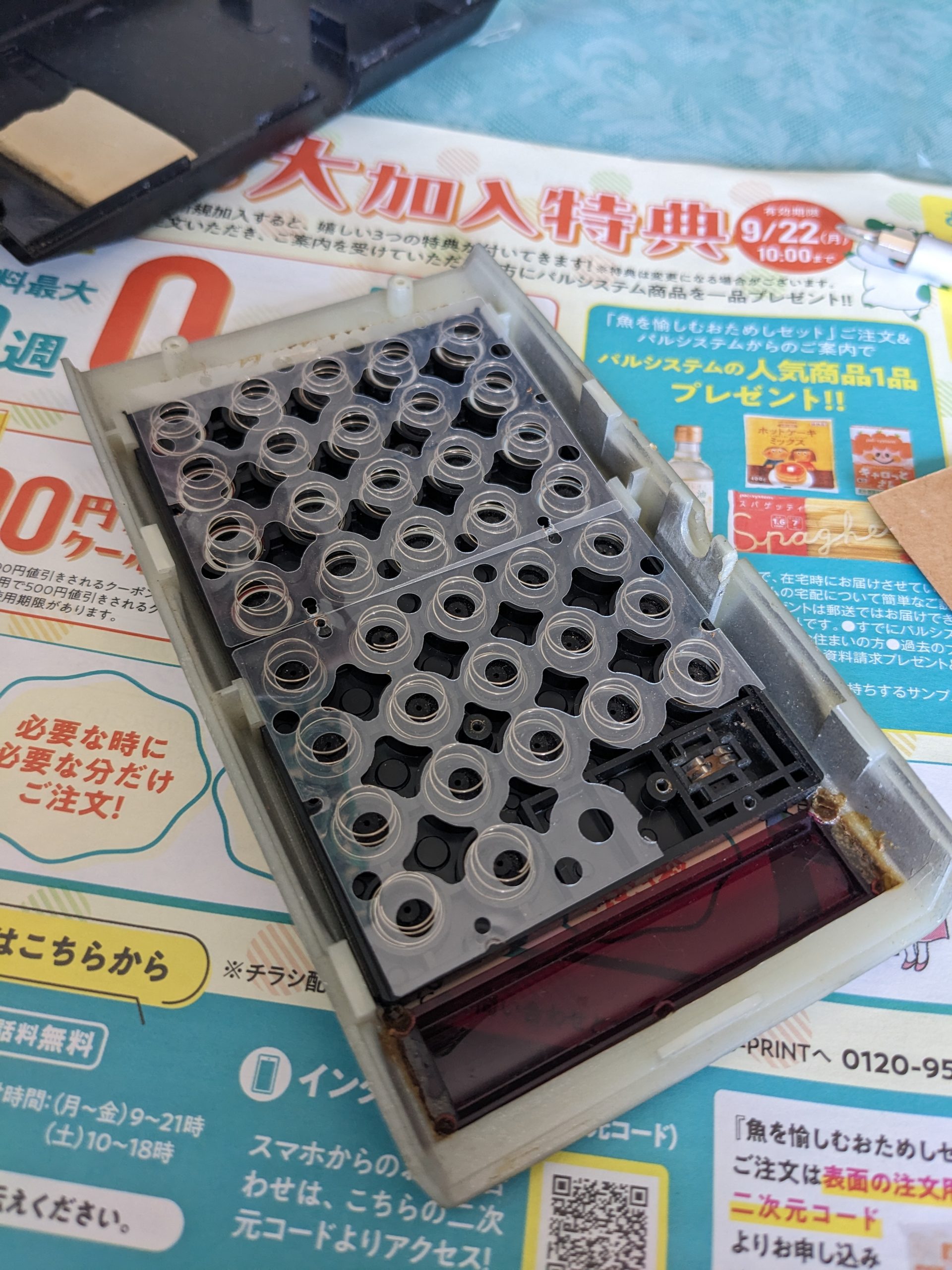
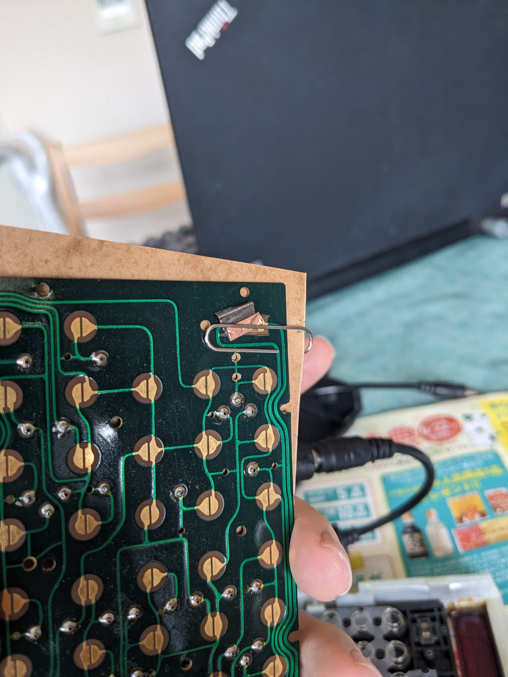
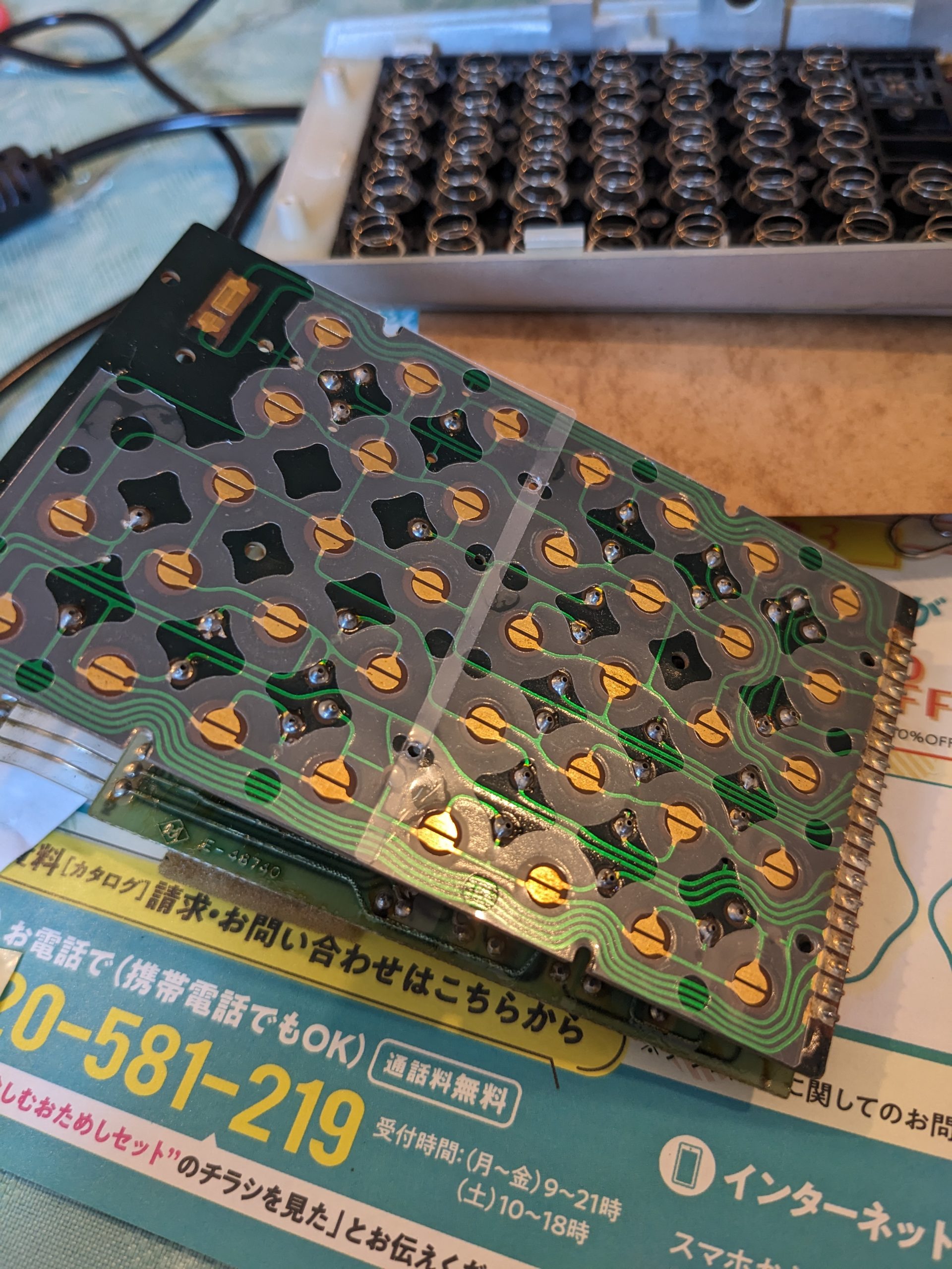
Here we are. The mainboard and the key-board are sandwiched together, and can be opened, a bit like a book. Just like the ZX81 RAM expansion! Pay no mind to the Japanese, it’s just a piece of spam I found in my mailbox.13 screws. Unlucky number?Here we are. The key-board! It’s just like an old computer keyboard.And here are the conductive rubber plungers and springs that make contact with the key-board. Again, just like an old computer keyboard! When putting everything back together, getting these springs aligned with the plastic sheet isn’t so easy. See last pic to find out how I managed to do it anyway!This is the power on/off switch. Using this bit of conductive tape that is no longer very conductive (?!) (Maybe the bridge here just needs a lot of current, more than the adhesive side of the copper tape can support), and a clip, I can force the power to be on so I can check what’s going on with the 1 key. It turned out that it worked just fine and just needed a bit of cleaning.On the way out, I used a small amount of glue to hold the plastic sheet in place. Otherwise I’d probably still be sitting there.
I recently bought a 3D printer, and also recently acquired a new, very popular hobby (for my standards at least): I have a tiny 10 cm × 10 cm × 10 cm fish tank on my desk! What to do with such a tiny fish tank? Well, it’s not all disadvantages.
Disadvantages:
You can’t put in a lot of things to look at
You can’t put in filters, heaters, or other large devices. Even most fish nets are too big.
You only put in about 0.8l of water, so there is not a lot of thermal mass. The water temperature quickly rises or falls to the room temperature.
…
Advantages:
You only put in about 0.8l of water, so it’s very light. You can easily carry the thing around, put it next to somebody else, turn it around, take it to your bathroom (etc.) when performing maintenance.
It will never tip over.
I have a couple Cabomba plants in it. And apparently the Cabomba had at least one pond snail egg on it! So after two weeks I suddenly had a pond snail too! It’s super cute in my opinion.
Snail-kun, with mouth open. Probably Radix auricularia japonica. Currently cleaning the glass. Can also be observed moving along the water surface while submerged, i.e., upside-down! スネールくん(モノアラガイだと思う。この写真ではガラス面を掃除してくれているが、水面を逆さになって這うこともよくある。割と観察が楽しいタニシじゃないでしょうか。モノアラガイの漢字は物洗貝、だそうです。)
Cabomba plants seem like they would like to grow tall. In fact, they were already much taller than my tank when I got them. So I planted them “diagonally”, and they seem to be okay with that. I have the tank for a month now. Initially, some of the cabomba plants developed white mold-like growth on the tips (which were already protruding from the surface of the water), so I got rid of those, but I still have plenty.
Initially I’d thought I’d like a tiny fresh-water shrimp in the tank, but I decided against it because they’re apparently really fussy about water quality. Plus the Cabomba plants may still have residual pesticides on them.
Making the 3D model
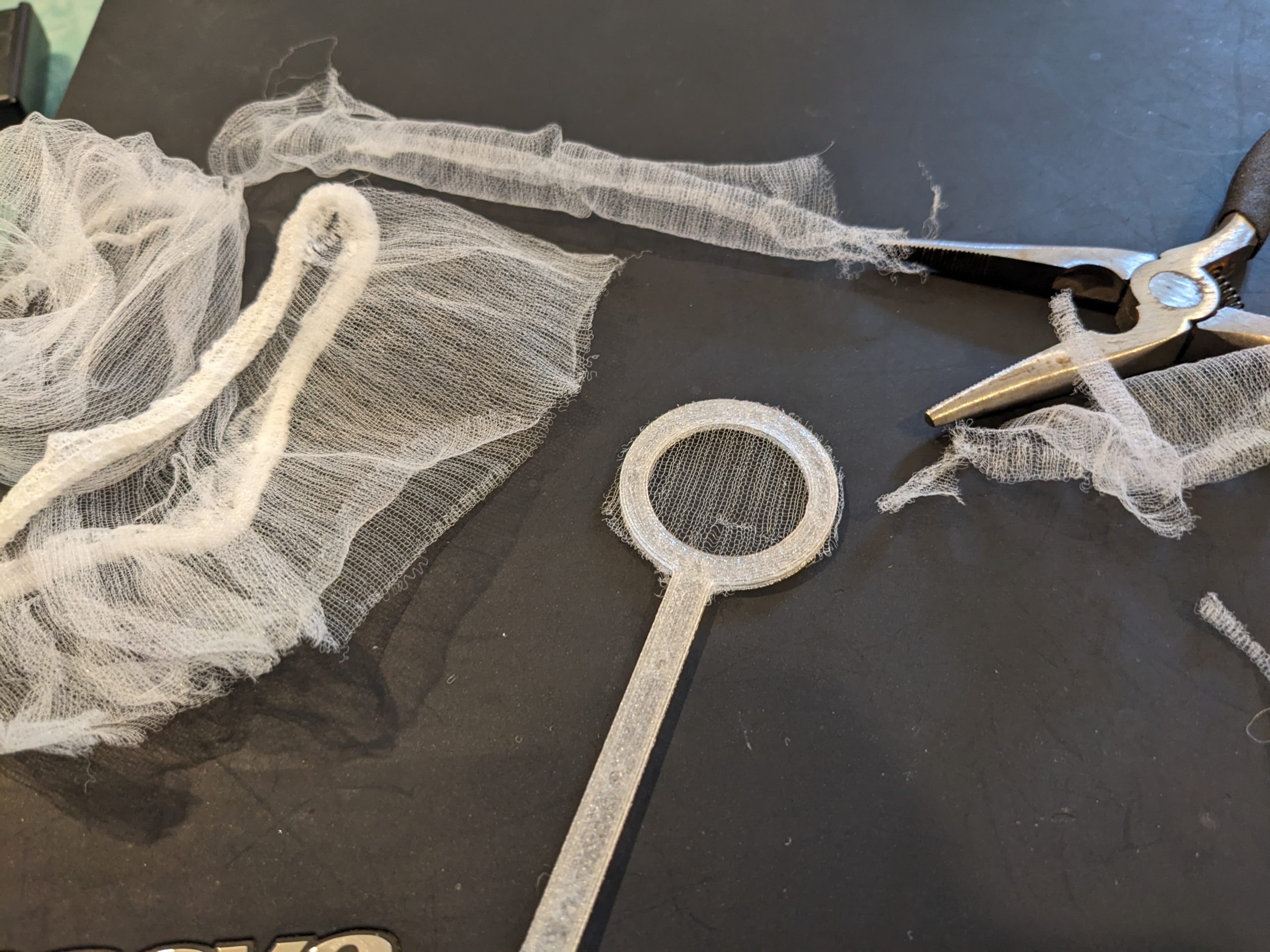
So, since most fish nets are way too big, I decided to DIY it with the 3D printer and some mesh material I had lying around, namely, kitchen sink strainer mesh bags.
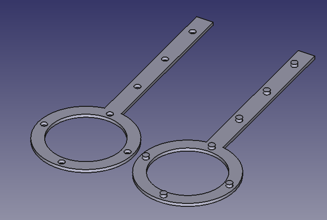
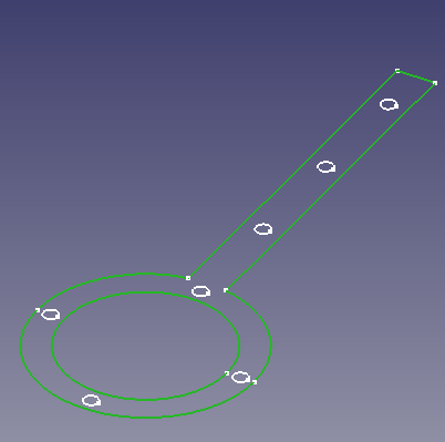
After buying the 3D printer (also about a month ago), I learned how to use FreeCAD. Making this 3D model took less than 10 minutes. Here’s how:
Use the arc tool to draw the round parts of the outer edge.
Use the line tool to draw the holder.
Use the circle tool to draw the inner hole.
Use the circle tool to draw the small holes (seen on the left side in the image above). I used a diameter of 2 mm.
Use distance constraints to space them evenly.
Apply “Pad”. I chose 1 mm.
If you’re satisfied with the result, duplicate the entire body (copy and paste).
Delete the padding in the new body. We will pad different parts of the sketch individually.
Select just the outer frame, like in the image below.
Pad by 1 mm.
Then select just the small circles, and pad by 2 mm.
You’re done!
You can now print out the file. Put the mesh material between the two parts of the holder, and use pliers to mate the protruding parts with the holes. (Bambu A1 Mini, standard 0.4 mm nozzle, bog-standard PLA, selected “precise wall” in OrcaSlicer. Your mileage may vary!) You may or may not need to use pliers (to create more force in a small spot) to mate the two parts of the holder together.
Like this, aight.
3D model
Here’s an archive with the .FCstd (FreeCAD) file and a .3mf file:
Update 2025/05/17: It turns out that connecting Rigol scopes to the network can be very useful sometimes. Apparently you can connect your Rigol directly to PulseView by doing Connect to device → Rigol DS (rigol-ds).
Update 2025/05/21: I also have access to a Siglent SDS 1202X-E, and while (AFAIK) PulseView can’t be connected to this scope, I was able to perform a binary dump (it’s in the export options) and load it in Audacity and go from there (just as described below) just fine.
In this post, we export what we see on an oscilloscope to some odd raw format, load it in Audacity and fix it up a bit, load it into PulseView, and set up a logic analyzer decoder. This is not necessarily USB-PD-specific, you can use this to turn your oscilloscope into a logic analyzer and protocol decoder, albeit with very few channels. (Note: most oscilloscopes have decoding built in for common things like I2C. But maybe PulseView’s interface is a little nicer, so this technique might help in those cases too.)
The Rigol DS1202Z-E doesn’t have USB-PD decoding built in. Too bad. Maybe it’s available in newer scopes?
USB-PD starts when a connection is made. In my case, I’d like to check up on the negotiation between a charger (source) and a Raspberry Pi 5 (sink). It’s likely that the Raspberry Pi 5’s USB-PD negotiation is defective, but that’s a topic for another post.
USB-PD works with a really low voltage level, which most logic analyzers probably don’t support directly. Oscilloscopes aren’t that picky, fortunately. All we have to do is set up a trigger on the right voltage, with a time base that will allow us to get as much data as possible (I went with 100 ms for now).
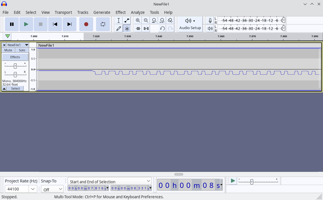
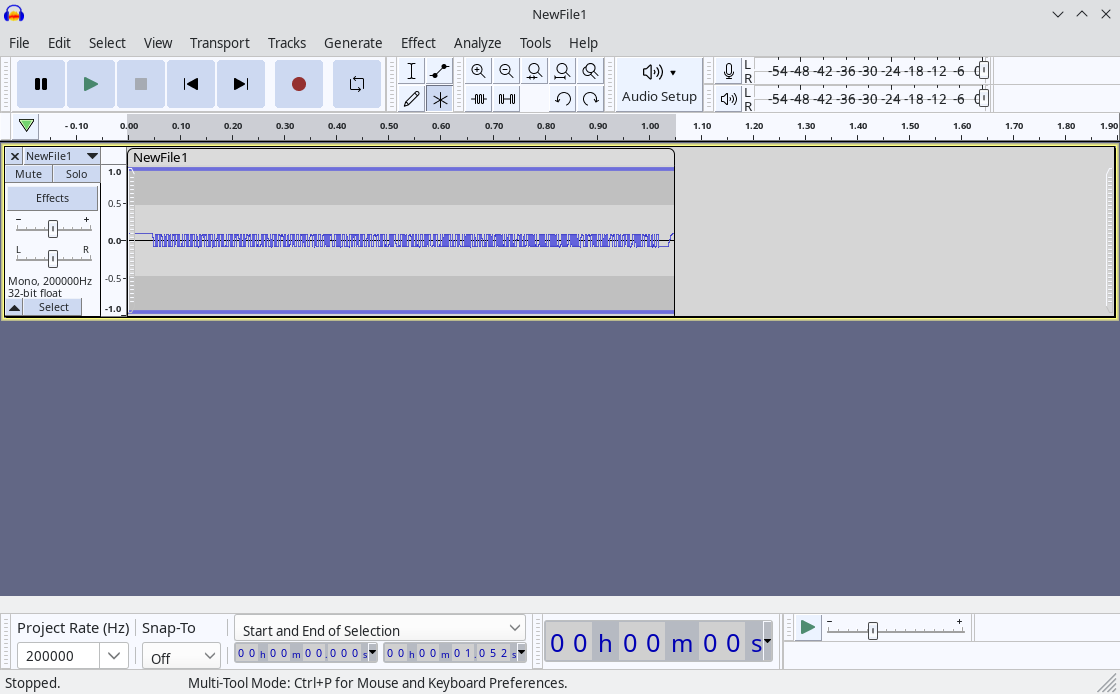
We need to store this data on a USB stick. The Rigol DS1202Z-E supports “CSV”, “TRC”, “WFM”, and probably a couple others. As you may have found out by now, getting it to save a CSV file with the entire memory takes a long time, so let’s not use that. Instead, we’ll use WFM. Done. How do we open this WFM file? We open it in Audacity! File → Import → Raw Data → NewFile1.wfm. Pick “Unsigned 8-bit PCM”, “Default endianness”, “1 channel (mono)”, start offset 0, amount to import 100%, sample rate: whatever you like. The actual sample rate is obviously incredibly high and audio sample rates are incredibly low, so I don’t think Audacity supports entering 200 MHz. (All right, I entered 200000000 Hz but it turned that into 384 KHz, I think. 200 KHz works BTW!) You should now be able to see in Audacity the wave form you saw on your oscilloscope, like this:
Imported at 44100 Hz.
What you need to do beyond this point depends on what you want to do. Duh! Well, I want to decode USB-PD. So here’s what I did next:
Next, we cut off any sections we don’t need (select using mouse and press “Del” key).
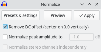
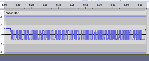
Next, we remove the DC offset (Effect → (Volume and Compression →) Normalize → Remove DC offset (center on 0.0 vertically), uncheck “Normalize peak amplitude”). (In newer versions the “Effect” menu is sorted by category, in older versions it isn’t.)
Much better!
Next, maybe amplify the signal a bit, if you like. (Effect → (Volume and Compression →) Amplify
Amplified.
Next, go to File → Export → Export as WAV, select “Signed 16-bit PCM” and save as a .wav file.
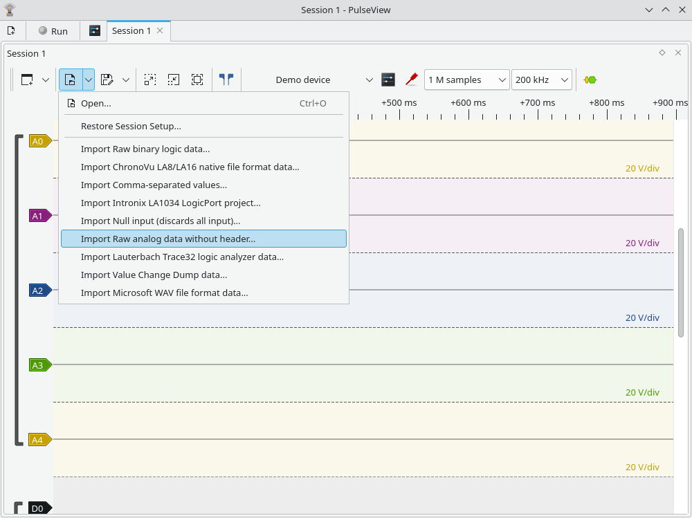
Next, open this file in PulseView, but not as a WAV file, but as a raw file, like this:
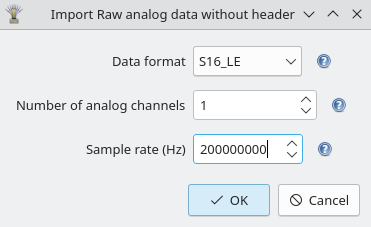
Note: files ending in .wav will not show up in the file selector, so choose Filter: All Files. Data format is S16_LE, number of channels is 1, sample rate is 200000000 in my case; this depends on your oscilloscope and its settings.
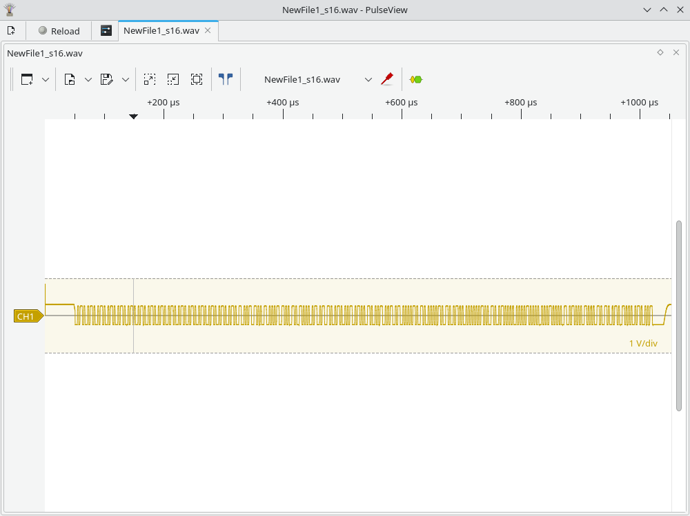
This is the result. Note that we have some junk at the beginning because of the WAV header. Feel free to get rid of it if it’s no good for your use case.
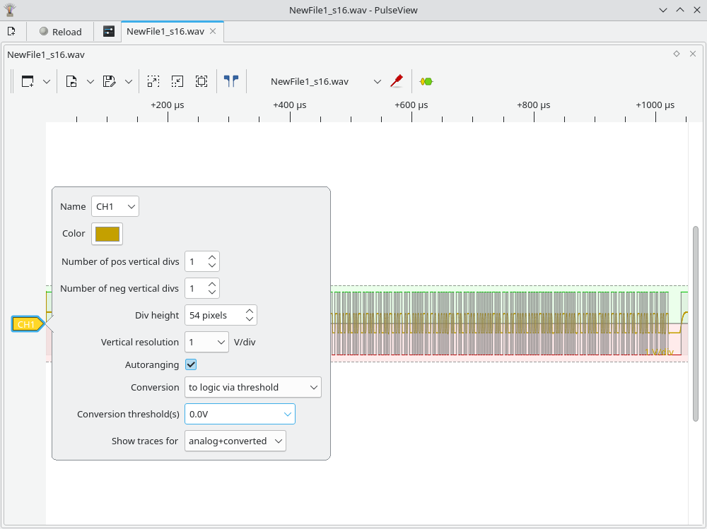
Next, click on the “CH1” arrow on the left side, set it to convert to logic, with the threshold at 0V.
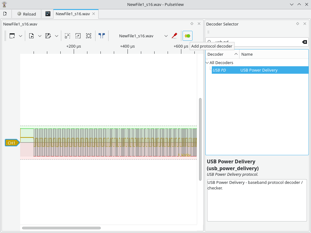
Next, we need to add the USB-PD decoder. Press the yellow/green button in the toolbar, search for “usb pd”, and double-click the “USB PD” item.
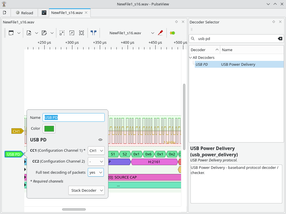
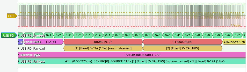
Next, press the “USB PD” arrow on the left side and set CC1 to be CH1, and optionally select “Full text decoding of packets”: yes.
Done!This charger advertises 5V at 3A max, and 9V at 2A max. Matches exactly what it says on the charger!
Back in the days of the Apple II, you could apparently run off to Akihabara and get the same computer with possibly better components for less money. Or just the parts you needed.
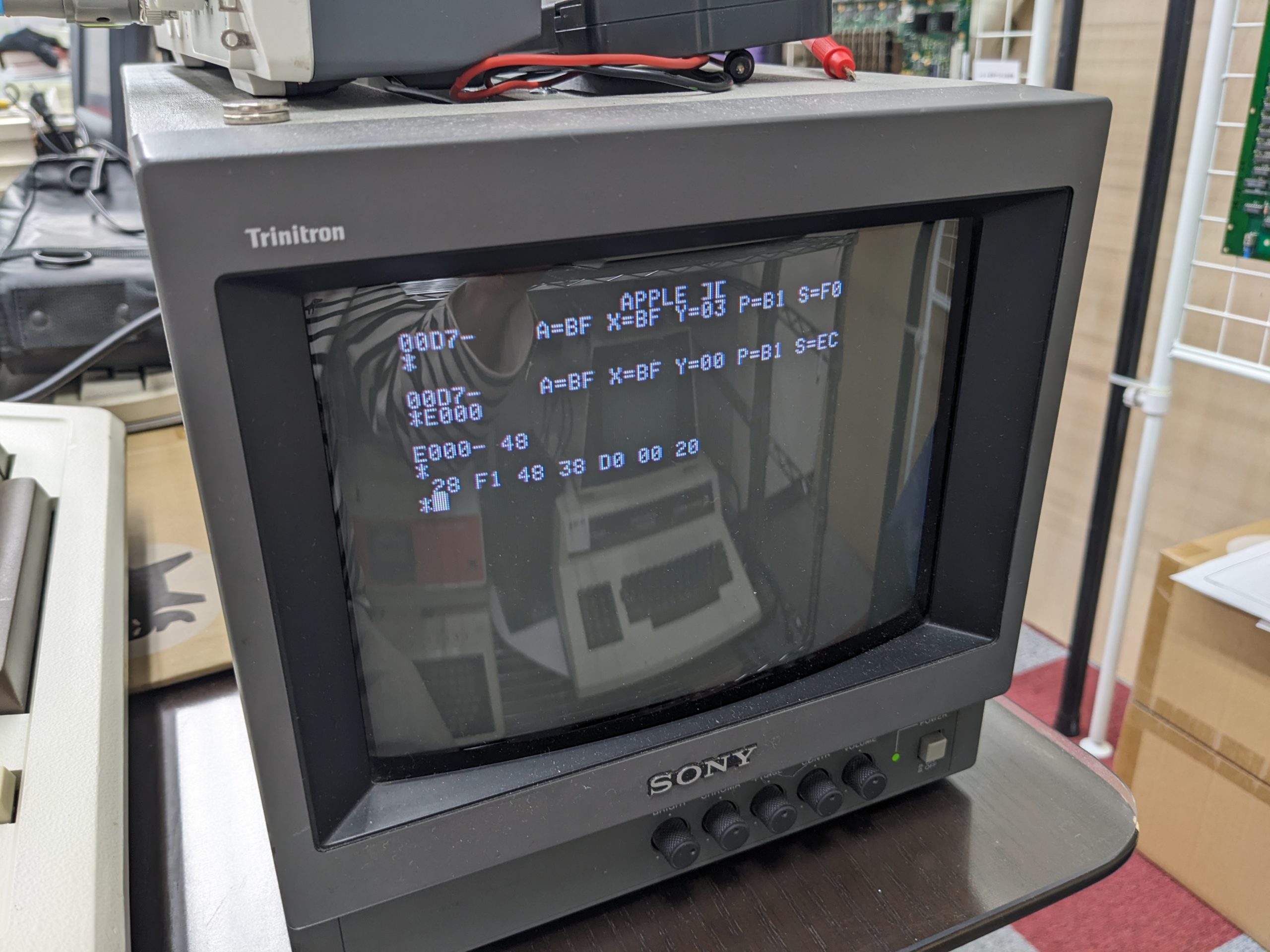
I had a chance to look at such an Apple II Plus clone that wouldn’t boot into BASIC. It beeped and displayed “Apple ][” at the top, but didn’t go anywhere from there. Pressing Ctrl+Reset made it produce another beep, but nothing happened on the screen. Sometimes it beeped twice. Once in a blue moon it would enter the monitor. And as I found out through trial and error, it would also enter the monitor when I pressed Ctrl while turning on the power switch on the PSU.
Before I did that though, I checked the voltages, and they were pretty low, near 4.6V, even with all expansion cards removed! (I also checked for hot spots to make sure there were no almost-shorts.) Fortunately the PSU supplied in this computer has a potentiometer that allows users to adjust the voltage without even opening the computer!
When you’re in the monitor you can check the memory, ROM, and do what you want! And since this is a popular system, you’re just one Google search away from getting some really cool incantations that you can paste^Wpeck in there.
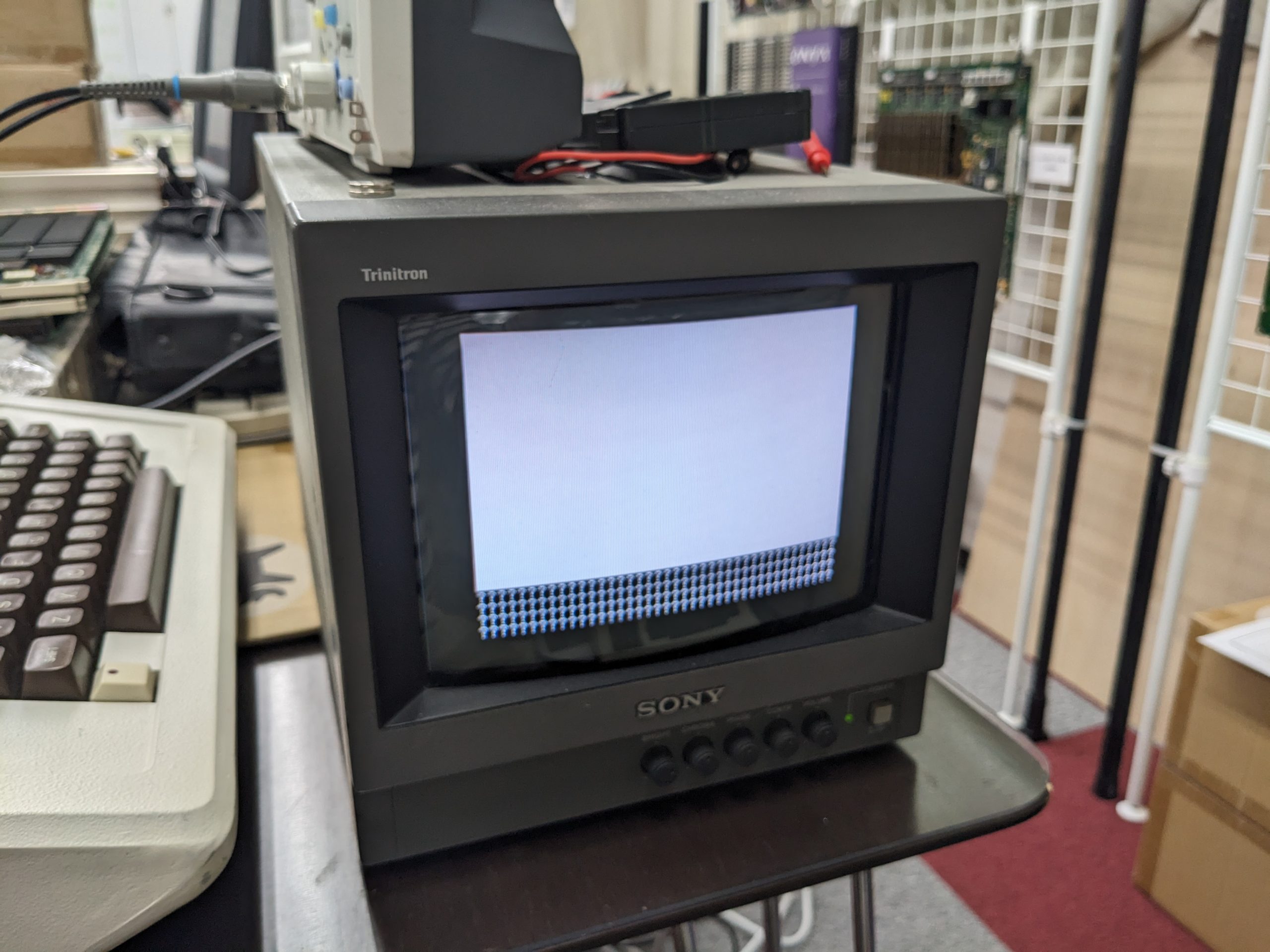
For example, I found something that’ll perform a memory test! This test passed with flying monochrome colors.
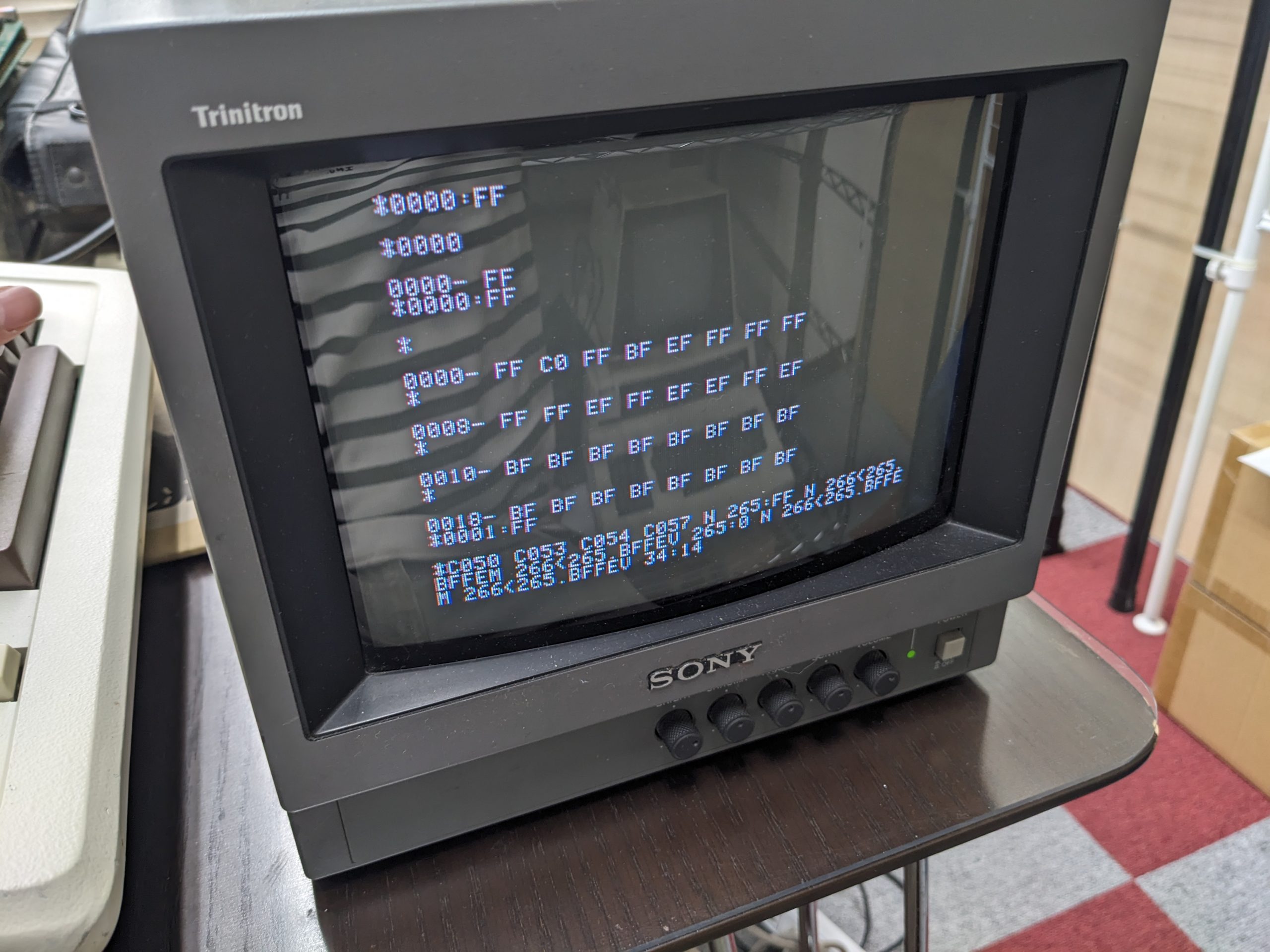
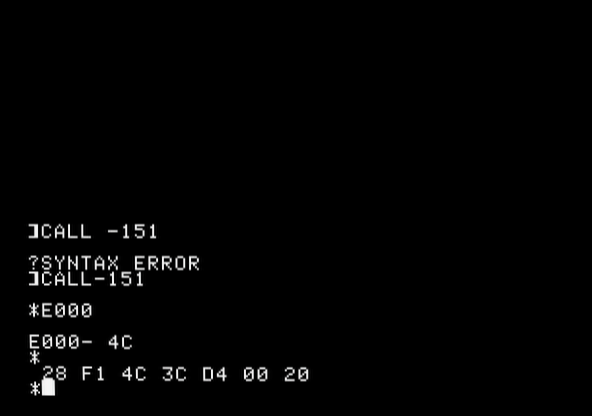
If the RAM is good, the ROM could be bad, or there might be a problem with a buffer chip, etc. So how do you test the ROM? Well, you go to https://www.scullinsteel.com/apple2/ on a computer (or phone), select the appropriate machine (][+ in this case) and enter the monitor by typing “CALL -151” (or “CALL-151”?). Then you type, e.g., “D000[return][return]”, and you’ll get the contents of the ROM at D000-D007. I had a look at the first 8 bytes of D000, D800, E000, E800, F000, F800. And guess what? E000-E007 were different!
Emulator On the real machine
E000 has 4C in the emulator, 48 on the real machine. E003 is the same. E004: 3C/38.
0x4C is 0b1001100. 0x48 is 0b1001000. 0x3C is 0b0111100. 0x38 is 0b0111000.
As we can see, it looks like one bit is refusing to come up.
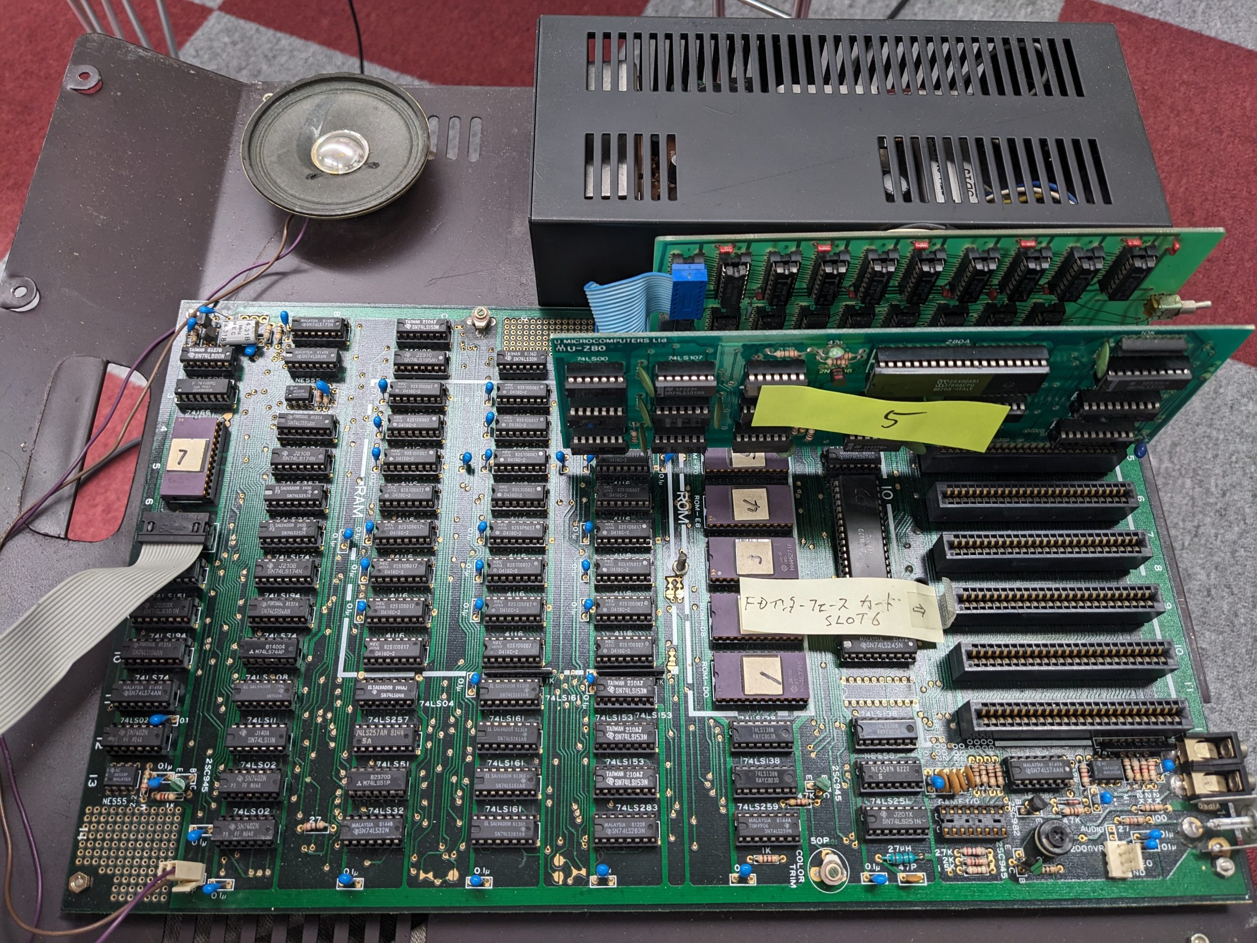
I took out the ROM for E000-E7FF (which is conveniently labeled E0 on the PCB), cleaned the pins and the socket, and put it back in. And that’s all that was wrong with it! (I’ll replace at least one cap in the power supply at a later date. Unfortunately it’s one of those huge high-voltage high-micro-Farad ones that aren’t available in my parts cabinet.)
Mainboard. The ROM chips are regular 2716 chips, which is pretty useful compared to e.g. 2316 or 2516. Plus they have gold-plated pins! There was no crustiness at all.
I recently had a chance to look at a malfunctioning Commodore 3040 floppy drive.
Smoke coming out of drive
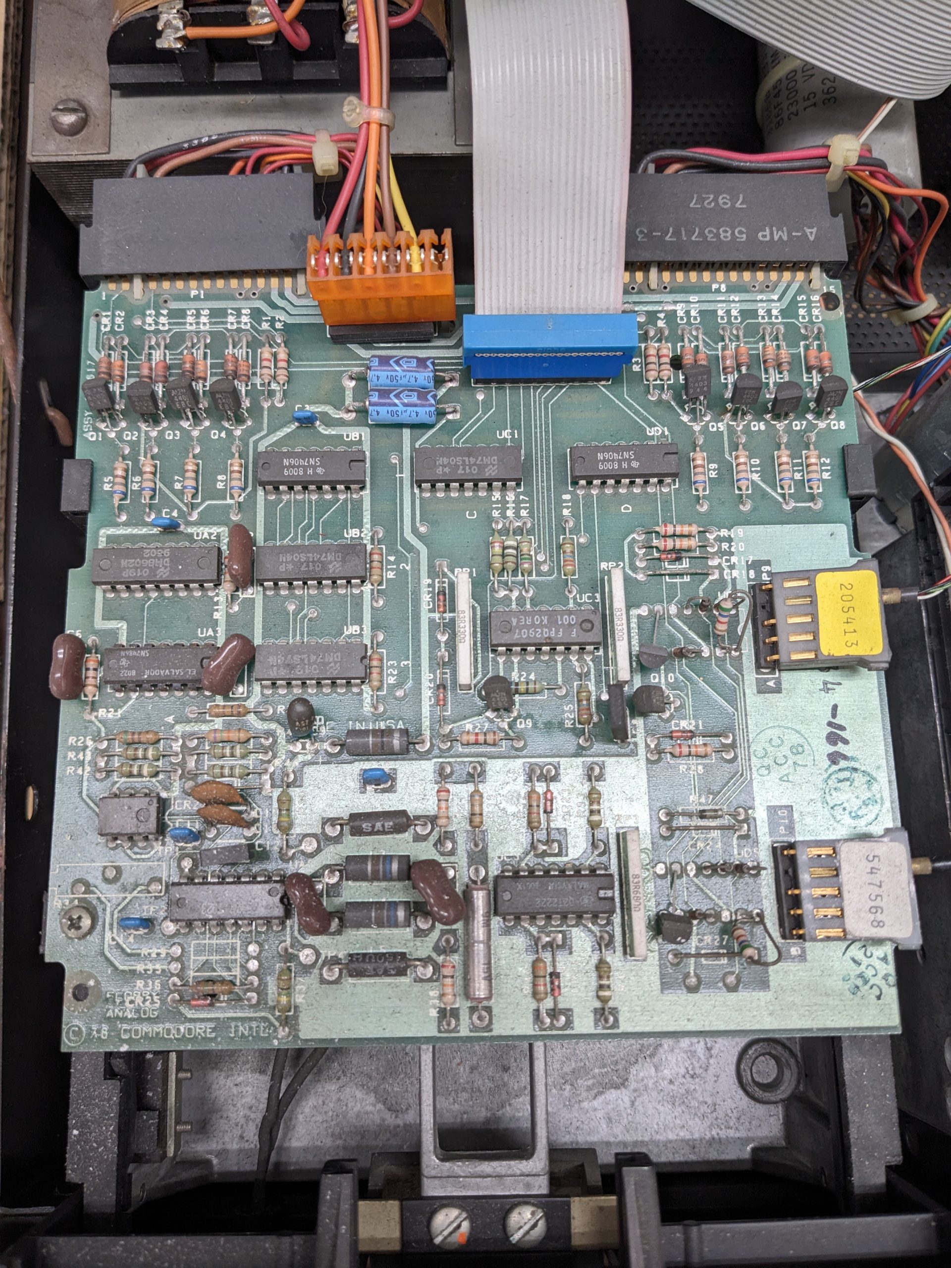
There is a real chance that yours too might emit magic smoke when you turn it on for the first time in decades. So before turning it on, be prepared to turn it off quickly, and then watch it like a hawk. Reacting quickly may prevent shorted tantalum capacitors from bursting. Check the schematics and BOM to see what kind of capacitor to use. (You’ll find all that at https://www.zimmers.net/anonftp/pub/cbm/schematics/drives/old/index.html)
The tantalum capacitor a little left to the center of the board (right over the “MADE” part of “MADE IN USA”) is all black, but hasn’t exploded.
Cleaning
Clean the heads. And if the drive looks really dirty on the inside (the case isn’t exactly dust-proof), do some general cleaning perhaps. It also makes it nicer to work on it!
Maybe move the head position manually a couple times, just to make sure the mechanism is not stuck.
It would probably be best to unplug all connectors and clean them. I did that for most. Before that, the drive would often just stop responding to commands.
PEBKAC #1
Being more accustomed to the Commodore 64’s 1541, I assumed you could just do LOAD “$”,8. Well, you can’t with early versions of BASIC and/or the DOS. You first have to make the drive read in the BAM. This is on the 18th track, first sector. And the drive currently doesn’t even know what track it’s on, so you must initialize it. So assuming that you want to talk to “drive 0”, (the 3040 has two drives, 0 and 1) the first command you execute (in BASIC’s normal interactive mode) is:
OPEN 1,8,15,”I0″ And then: CLOSE 1
(For drive 1 it’s OPEN 1,8,15,”I1″)
If you get an error light, which I did, you probably won’t succeed in getting a directory listing either. There’s an incantation you can use to get the drive’s error message, but it’ll likely just be “READ ERROR”:
10 OPEN 1,8,15 20 INPUT#1,A,B$,C,D 30 PRINT A;B$;C;D 40 CLOSE 1
Fixing the drive speed
The PET drives are belt-driven. The speed is controlled by a potentiometer on a small board attached to the drive. The belt is on the back side, and there is an indicator that helps determine if the drive is running at the right speed. This indicator works if you have lighting that goes on and off at 50 Hz (or 100 Hz or some other multiple) or 60 Hz (or 120, etc.). In the age of LED lighting, that will likely not be the case. If you want to know what frequency your light oscillates at, just use an infrared LED (a red or green LED will likely be fine too, or even other colors) and attach its pins to your oscilloscope probe’s GND and signal (it’s a floating device, so it doesn’t matter which way you connect it). If you hold the LED close to the light source, you should see an oscillating voltage and your oscilloscope will show it’s frequency.
Or… just attach an LED to a microcontroller and turn it on and off at the correct frequency.
Anyway, my drive speed was out of whack but in my case the potentiometer was just dirty perhaps. Moving it left and right a little bit fixed the issue.
Running drive diagnostics
Having logic diagnostics on a floppy isn’t very useful if the floppy drive doesn’t work, so let’s convert it to a wav file that we can play through the datassette drive with a 3.5mm to tape converter inside. Grab cbm_technician_disk.d80 from the aforementioned site, and use VICE’s c1541 program to run this:
Maybe VICE can do it too, but I use a program called prg2wav (https://wav-prg.sourceforge.io/) to convert this to a WAV file. I have some more explanations on how to use this program in this post. Just for my own notes, here’s the command I use to run the program:
If the test goes well, the floppy drive’s LEDs will blink in a random pattern.
Don’t have a datassette either? Well, the program is written in BASIC so you could copy it by hand. ;)
Since they were socketed, I decided to give the 2114 SRAM chips inside the floppy drive another separate test. I made a 2114 RAM tester a couple years ago, but reused the breadboard for something else. So I just took out the 2114 chips one by one and put them in the PET’s VRAM socket. I didn’t see any issues.
PEBKAC #2
I didn’t really know whether my media was good or not, so I put it in a working 1541 drive attached to a C64, formatted it, saved a small program, and took the floppy back to the 3040. This time, the initialize command worked! So I did LOAD “$”,8. The drive said it was loading, but never finished. (Also the LEDs were doing something weird?) After that, I tried formatting the disk again (on the 3040), and it finished without errors! However, LOAD “$”,8 still didn’t work.
At this point I decided to read up on how Commodore floppy drives actually worked. I found a book called “Inside Commodore DOS” and put it on my Kindle and read the first few chapters on the train on my way to work and other places: https://archive.org/details/Inside_Commodore_Dos_1984_Datamost_a
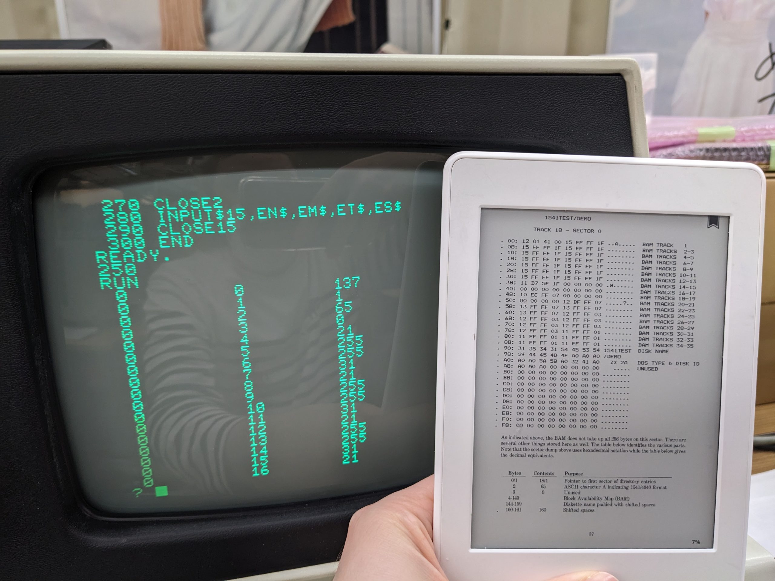
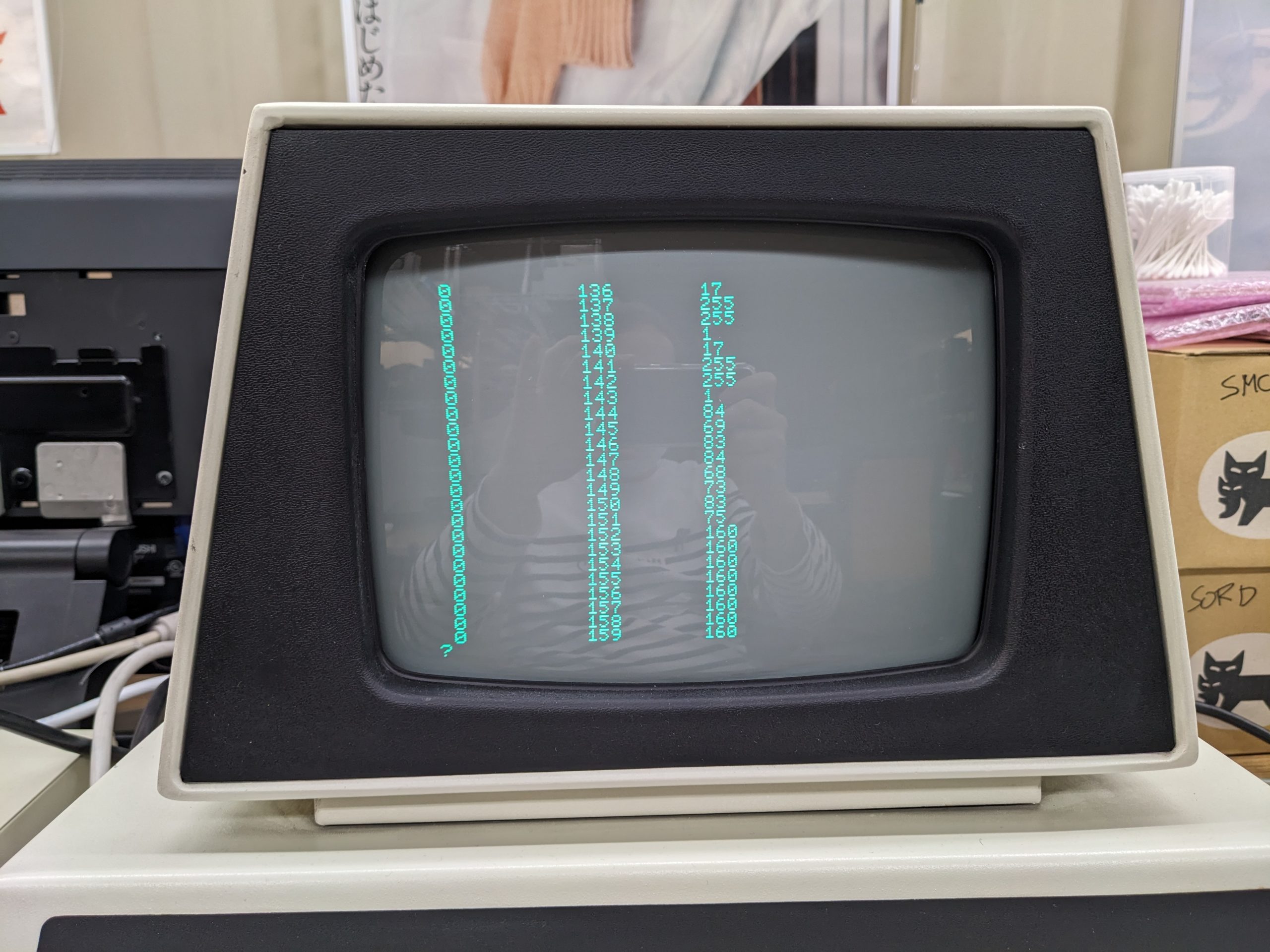
This book is mostly about the 1541, but most things didn’t change much, and it does mention some things specific to older drives as well. It explains how the BAM/filesystem works, and includes short example programs that do ~mid-level sector reads and print the result on the screen. I ran the program in chapter 5.3 (“Block-Read Command (U1)”) on page 74. And to my surprise, I got a decent result! The magic numbers looked plausible and the disk name (specified when formatting) too!
Verifying the first 16, er, 17 bytes. Note that the very first byte is different. But perhaps that’s just due to a DOS version difference? (Also you need to convert decimal to hex in your head.)Bytes 144-159 are the disk label specified when formatting. perl -e ‘printf “%c”, $_ for 84, 69, 83, 84, 68, 73, 83, 75’ => TESTDISK. Yay!
Next, I tried something that was mentioned earlier in the book… On the C64 you usually do LOAD “$”, 8, sure. But you can also do LOAD “$0”,8. The book said that this is a relic from earlier times when there were two drives per drive. And the 3040 obviously is from those earlier times! So the correct commands are…
LOAD “$0”,8 SAVE “0:FILENAME”,8 VERIFY “0:FILENAME”,8 LOAD “0:FILENAME”,8
And guess what, these commands fricking worked! Dammit.
Except the drive sometimes get stuck somehow, but that’s a topic for another day. (It seems like it’s in the communication part. I can turn the drive off and BASIC will return with a DRIVE NOT PRESENT error.)