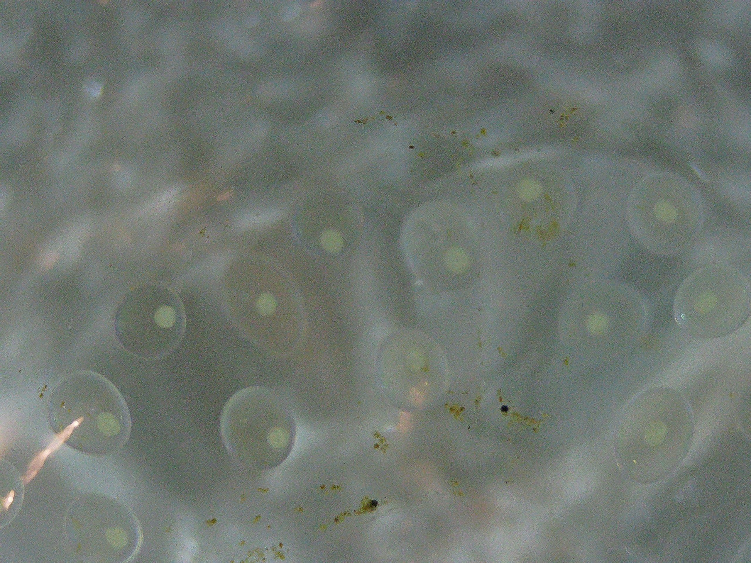
The single Radix auricularia japonica snail in my tank decided to reproduce, most likely all on its own. I believe it must have arrived on my Cabomba as an egg (bought about 6 weeks ago), but it’s also possible it actually arrived as a micro-snail and mated with another micro-snail… Now having actually seen how tiny freshly hatched micro-snails are, I don’t think it’s impossible it arrived as one. Below is a look at one of the newly hatched ones (there are over 10 in total) through a microscope. I also included a picture of its eggs. They are embedded in a jelly-like substance, and hidden inside the Cabomba.
カワ(・∀・)イイ!!Same magnification as above. (Different resolution though, so only the same if viewed resized to the same area.) I don’t know if these eggs are fertilized or not. 同じ倍率で卵の写真も撮ってみた。(しかし解像度が違うのでサイズを合わせた場合に限り同じ倍率。なはず。)受精済みなのかどうかわからない。
In my previous post from over 1 year ago, I noted that there was 1 W of power consumption even when my Commodore SR-37 calculator was switched off. In this post, we are going to investigate and tackle this problem, and fix a key that sort of worked when I got the calculator, but in the meantime stopped working completely. I also fixed the power supply (replaced the very worn cable) that came with the calculator, but for reasons I will explain later, we unfortunately won’t be able to use it with this device.
The power consumption issue
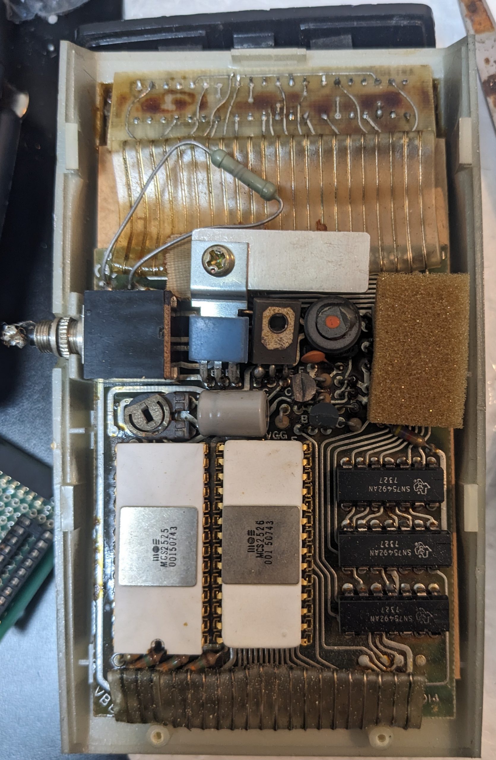
1 W of power consumption isn’t easy to hide in a confined space, because most of the time it’s converted to 1 W of heat. Let’s take a look with the thermal camera. Here’s a picture of the insides, again:
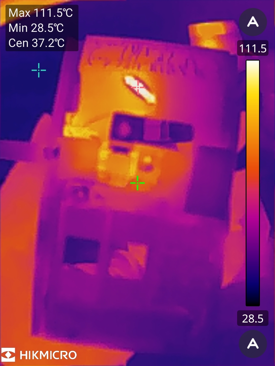
And here’s what’s getting hot:
111.5 °C, 232.7 °F
Okay, so it’s just that added-after-the-fact-looking weird-ass resistor sitting between + and -! It’s a 100 ohm resistor, the power supply is like 9V or maybe 10V. So that’s 1 W accounted for! There are no signs of rework, and the resistor looks quite antique, so I’m going to guess it was added at the factory. Why?
This resistor is sitting between positive and ground and effectively just puts a load on the power supply. This load will drop the power supply’s voltage a little bit. As the power supply is an unregulated linear power supply, the unloaded voltage will be 12V or so. Applying a load will drop this to 9V or less.
The power supply’s voltage is applied to the SN75492 LED display driver chips. These are rated for 10V. Do you see the problem? Without enough load, our power supply will supply a larger voltage to these chips. It would be a little bit cleverer if they had put the resistor somewhere that is interrupted by the power switch, but as they say, “why clever if dumb OK and just 111°C”?
By the way, it’s possible that this calculator sometimes(?) came with rechargeable batteries, and that the recharging circuit adds enough load to make the power supply suitable for this calculator. I don’t know if this is the budget version without the rechargeable batteries, or if they deteriorated and were removed somewhat professionally. The backside of the calculator has some basic instructions on it, and mentions charging:
Turn machine off when not in use. It is recommended that the unit be charged over night to assure maximum DC performance.
Anyway, I removed the resistor, and measured the voltage on the SN75492 chips. It was 9.4V, so we should be good, no? Well, maybe these chips came from a batch that was less tolerant of voltages closer to 10V, cause the display is “doubled”. When you display more (by e.g. pressing 888888) the voltage drops some more, and the problem disappears. When you use a different power supply that supplies a little less voltage, the problem also disappears.
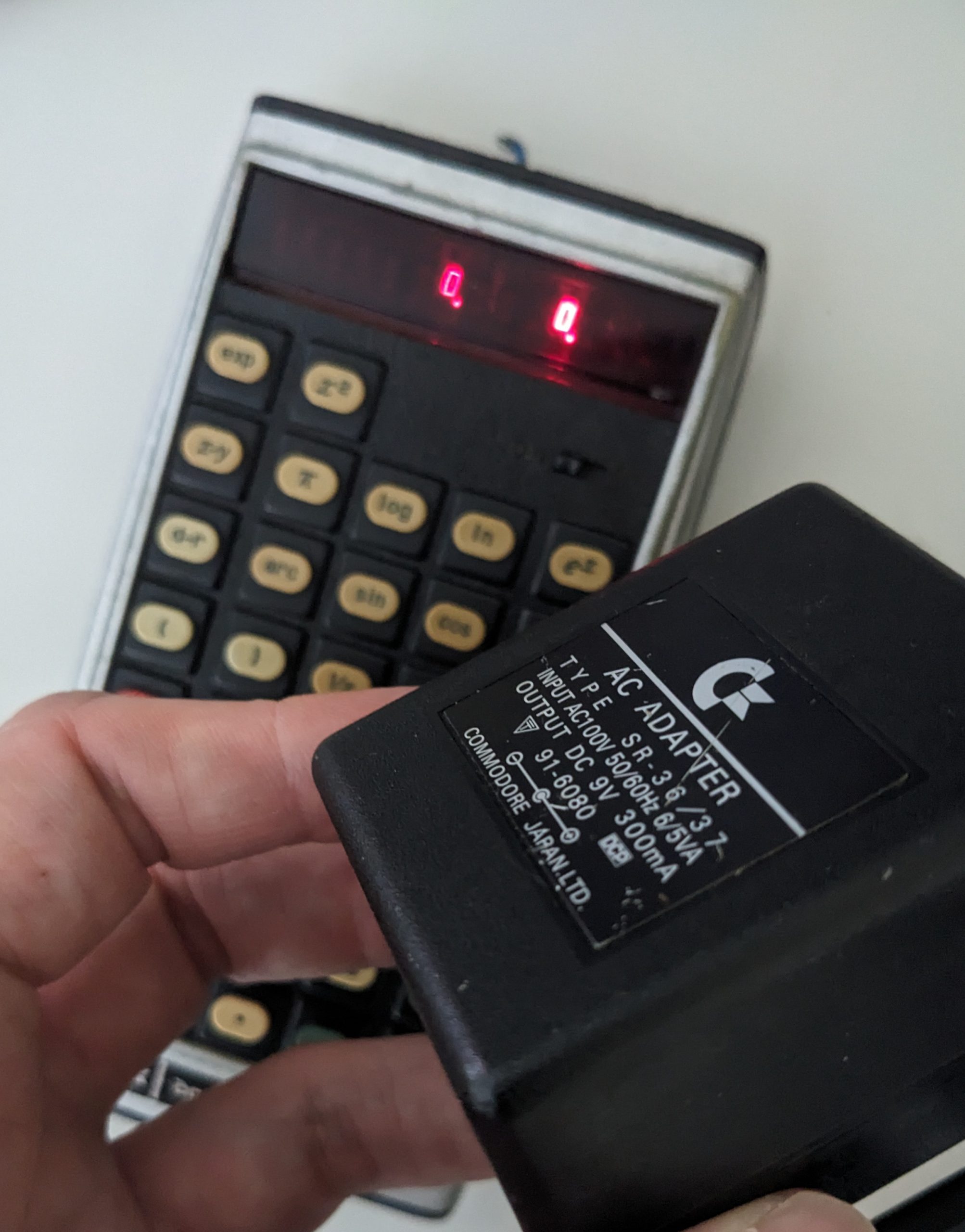
The pictured power supply is the one that came with the calculator. (The cable had deteriorated, so I’d replaced it.) Having repaired this thing, I was looking forward to using it. So I’d thought of building a small modular thing I could between it and the calculator to drop the voltage a little bit, perhaps using a four diodes in series, which would waste less power than a resistor. Unfortunately I made a couple soldering mishaps and ended up trashing that project, oops. At least the power supply is still original and usable with other old devices, e.g. my ZX80 replica!
So, let’s see what else we can do? We tried 7V. Works. Non-standard, inconvenient. What about 5V? Turns out that 5V works!
… Or does it?
Things that are unusual when running the calculator @ 5V
First of all, we need to define what 5V means. Have you ever measured the voltage coming out of a USB-A power supply? Most often, it’s 5.1V. Sometimes, it’s 5.2V. It can be higher, but usually doesn’t get higher than 5.5V. According to the USB specs, however, it’s 5V +- 5%, so 4.75V to 5.25V.
This calculator will run at any of these voltages. However, the lower the voltage, the darker the LED display. No problem. Anything else?
Well, would you believe me if I told you that it starts making “mistakes” when the voltage is too low? Specifically, division appears to go wonky at lower values of 5V. E.g., 8/4 is no longer 2:
8/4 = 2. 8/4 = 2. 8/4 = … 0.3003003. Note that the power supply’s display isn’t 100% accurate and is usually off by 0.2V.
Anyway, I’ll run it at 5V because I have plenty of power supplies that output various kinds of 5V.
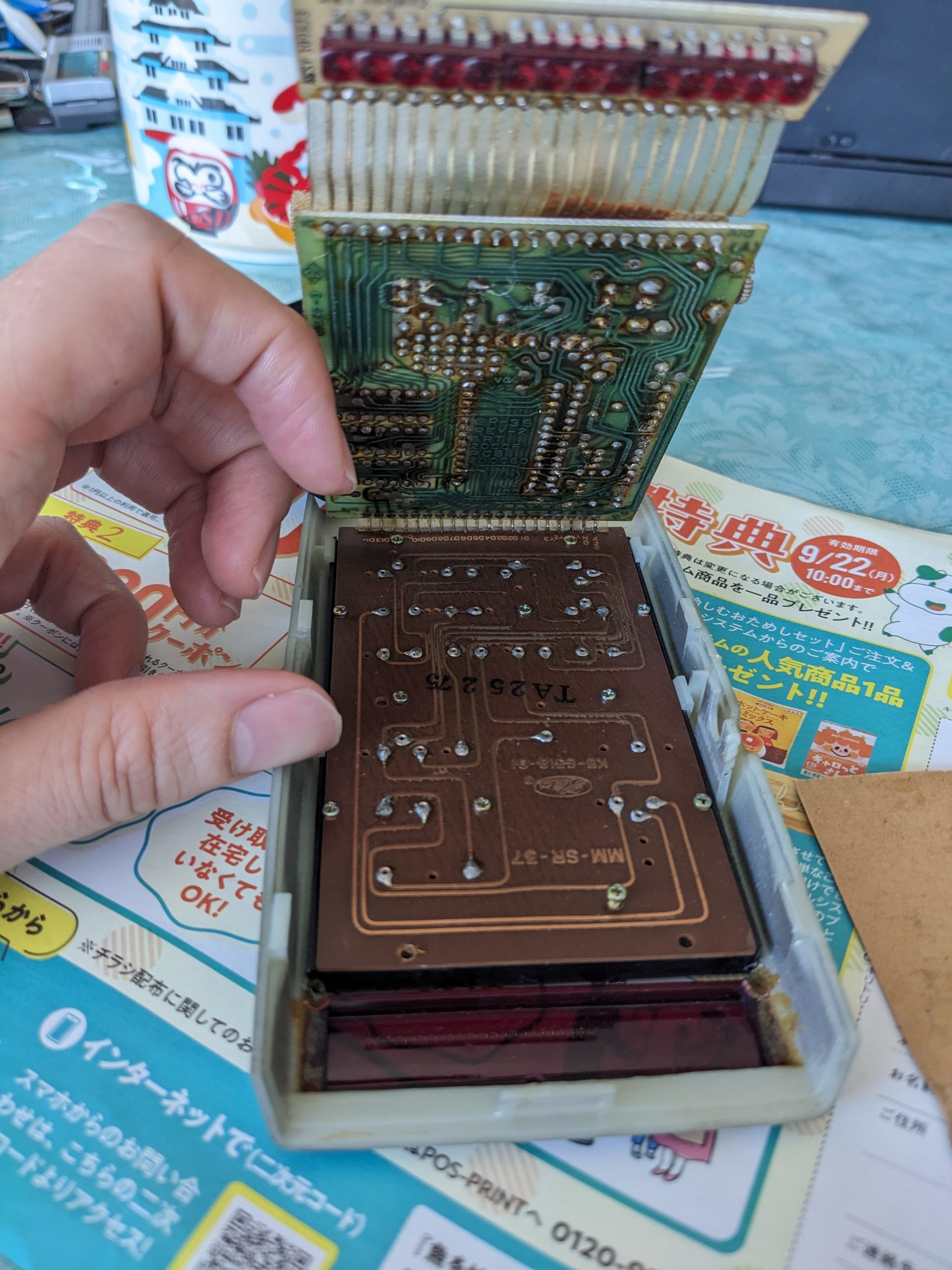
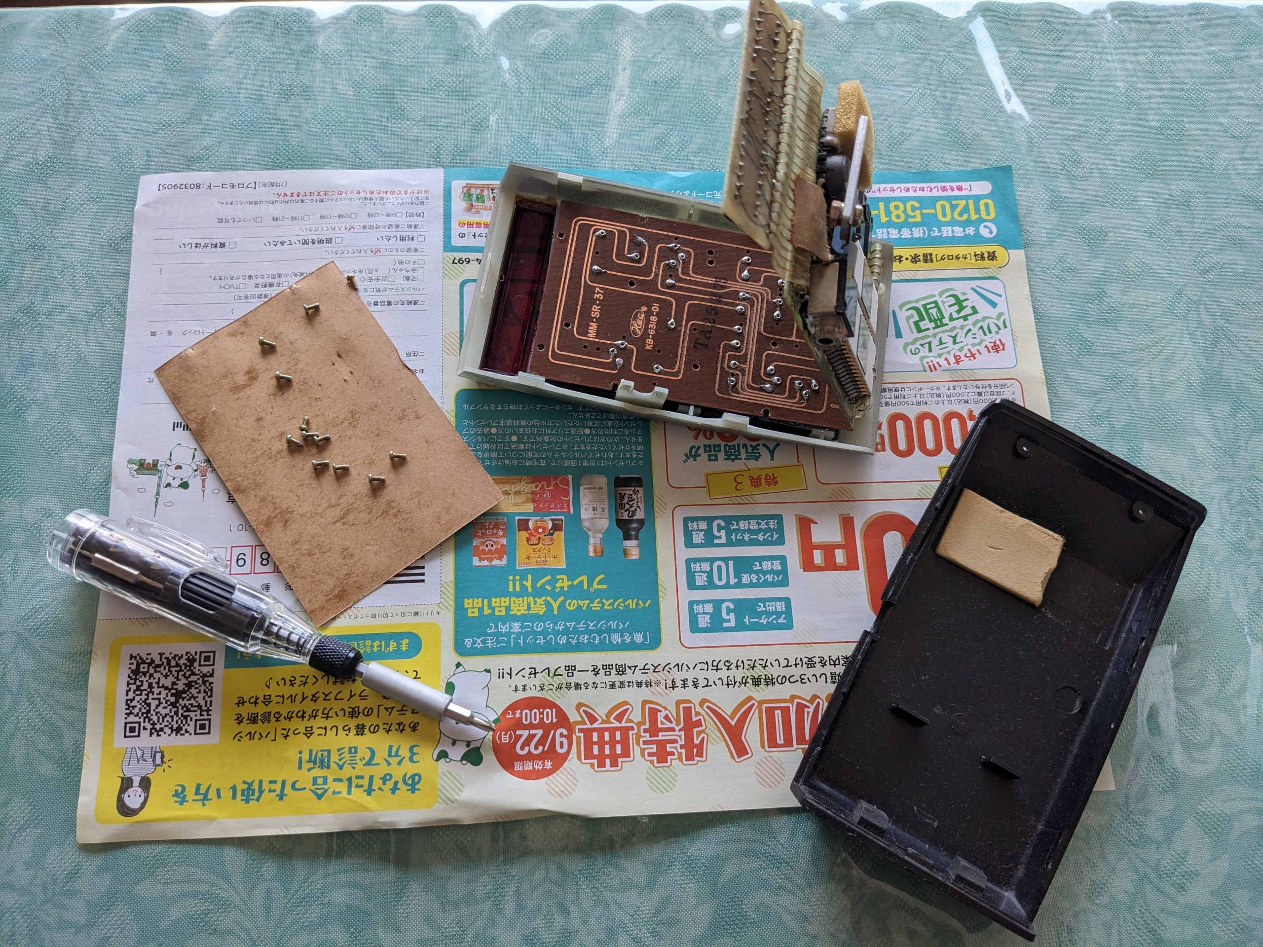
Fixing the ‘1’ key
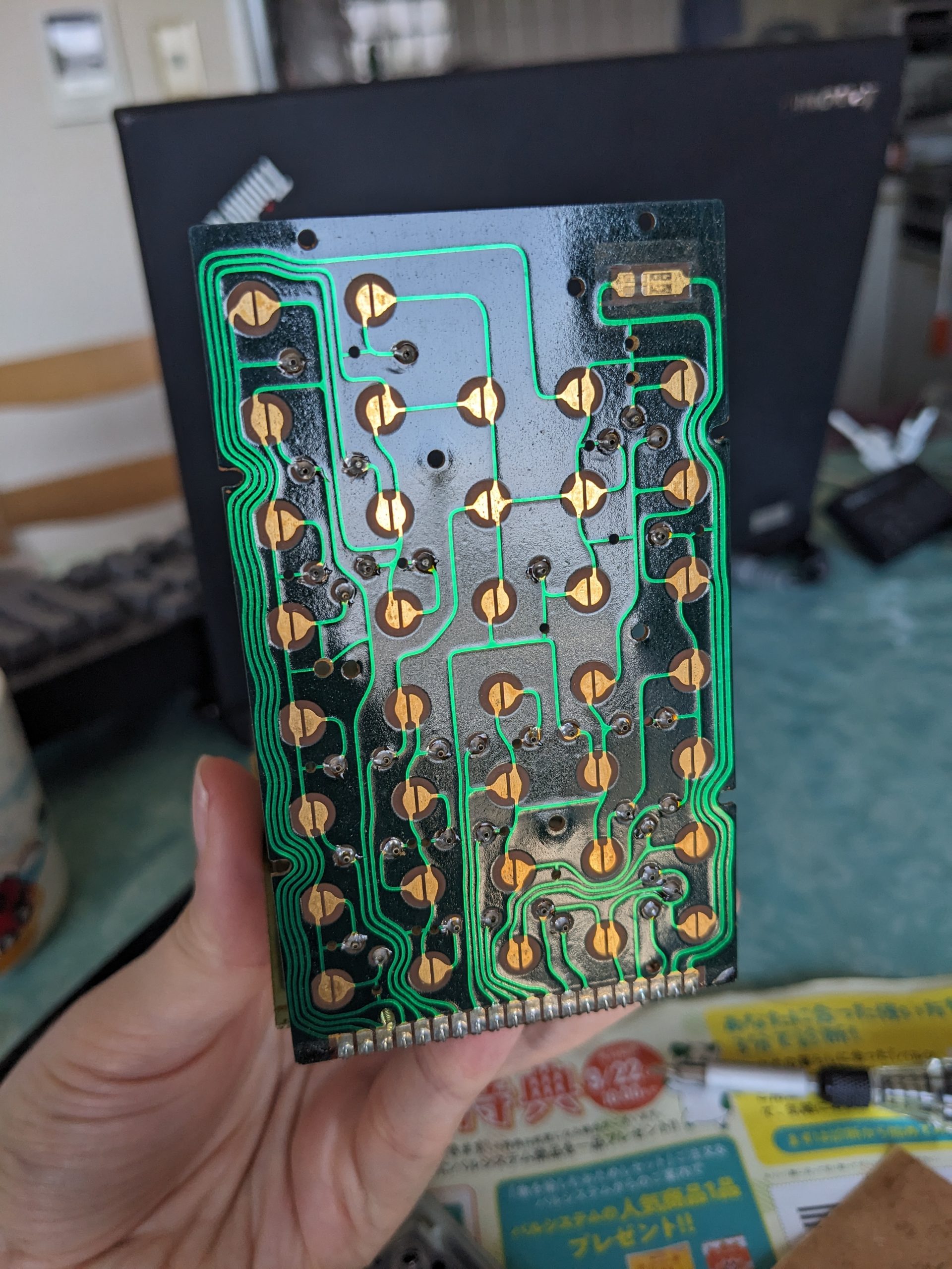
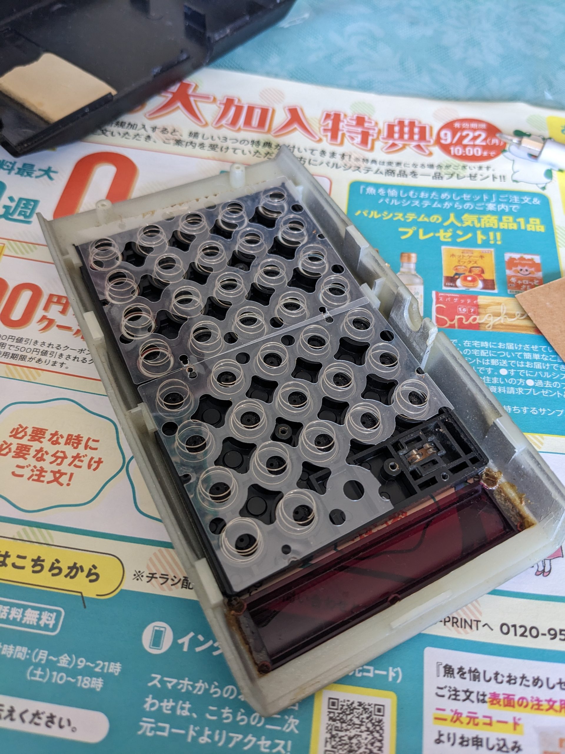
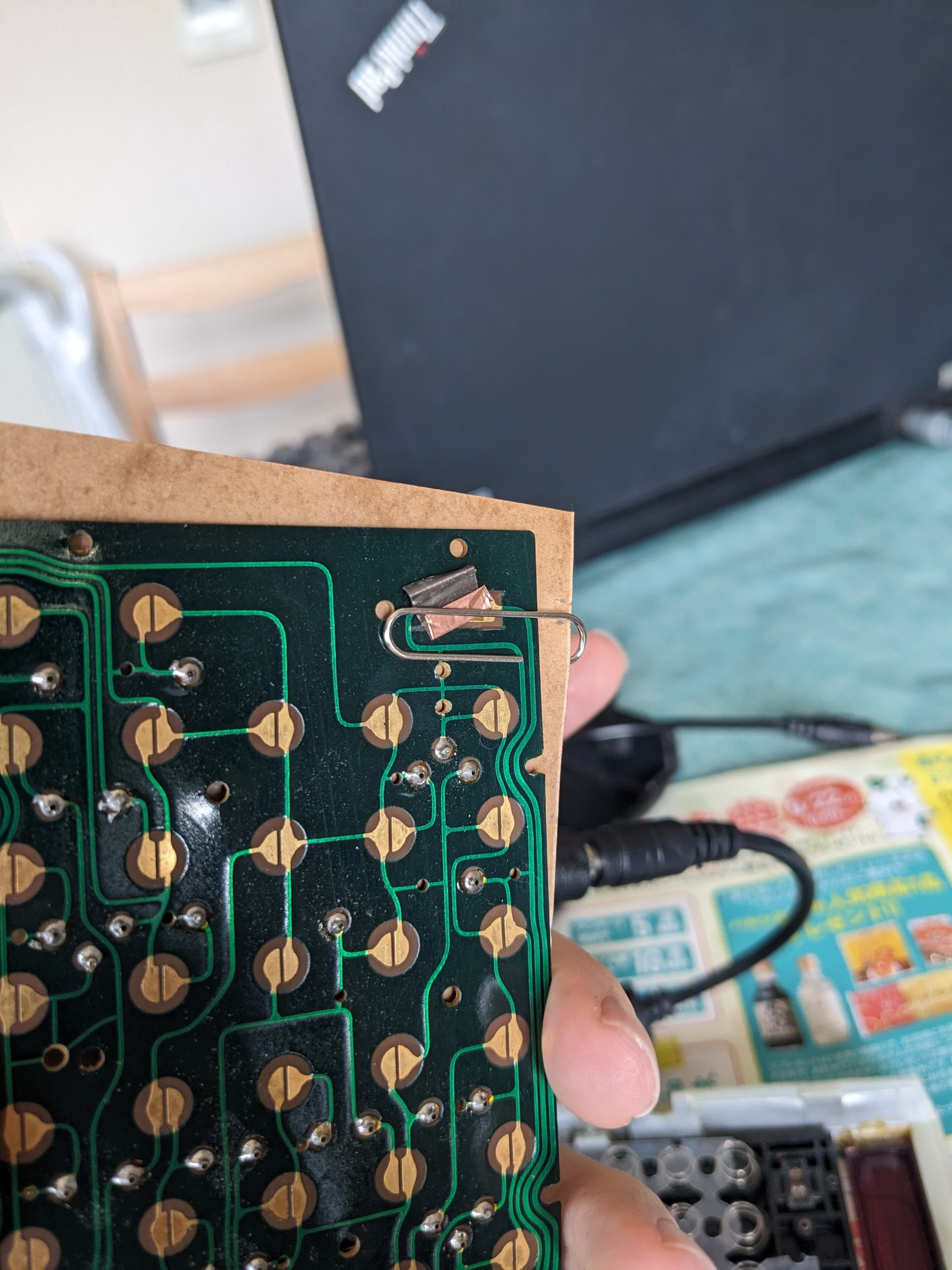
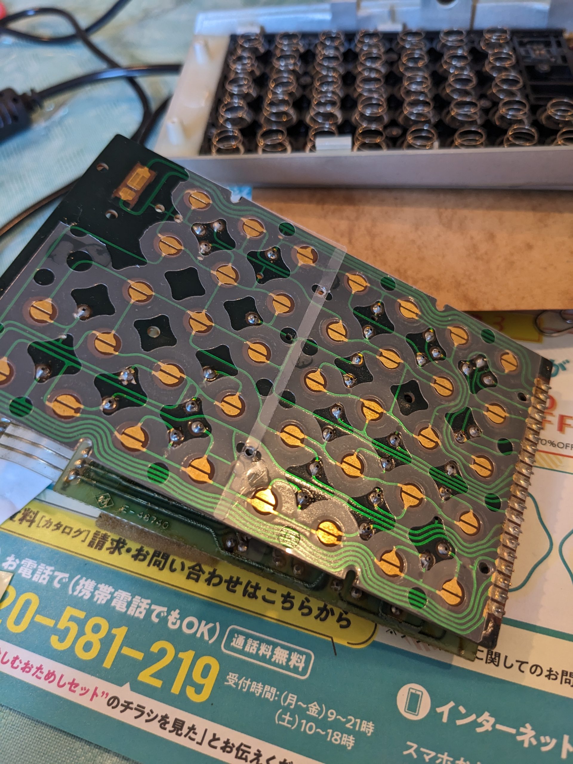
Here we are. The mainboard and the key-board are sandwiched together, and can be opened, a bit like a book. Just like the ZX81 RAM expansion! Pay no mind to the Japanese, it’s just a piece of spam I found in my mailbox.13 screws. Unlucky number?Here we are. The key-board! It’s just like an old computer keyboard.And here are the conductive rubber plungers and springs that make contact with the key-board. Again, just like an old computer keyboard! When putting everything back together, getting these springs aligned with the plastic sheet isn’t so easy. See last pic to find out how I managed to do it anyway!This is the power on/off switch. Using this bit of conductive tape that is no longer very conductive (?!) (Maybe the bridge here just needs a lot of current, more than the adhesive side of the copper tape can support), and a clip, I can force the power to be on so I can check what’s going on with the 1 key. It turned out that it worked just fine and just needed a bit of cleaning.On the way out, I used a small amount of glue to hold the plastic sheet in place. Otherwise I’d probably still be sitting there.
I recently bought a 3D printer, and also recently acquired a new, very popular hobby (for my standards at least): I have a tiny 10 cm × 10 cm × 10 cm fish tank on my desk! What to do with such a tiny fish tank? Well, it’s not all disadvantages.
Disadvantages:
You can’t put in a lot of things to look at
You can’t put in filters, heaters, or other large devices. Even most fish nets are too big.
You only put in about 0.8l of water, so there is not a lot of thermal mass. The water temperature quickly rises or falls to the room temperature.
…
Advantages:
You only put in about 0.8l of water, so it’s very light. You can easily carry the thing around, put it next to somebody else, turn it around, take it to your bathroom (etc.) when performing maintenance.
It will never tip over.
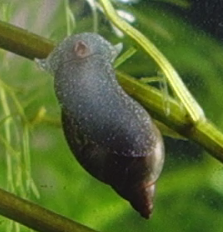
I have a couple Cabomba plants in it. And apparently the Cabomba had at least one pond snail egg on it! So after two weeks I suddenly had a pond snail too! It’s super cute in my opinion.
Snail-kun, with mouth open. Probably Radix auricularia japonica. Currently cleaning the glass. Can also be observed moving along the water surface while submerged, i.e., upside-down! スネールくん(モノアラガイだと思う。この写真ではガラス面を掃除してくれているが、水面を逆さになって這うこともよくある。割と観察が楽しいタニシじゃないでしょうか。モノアラガイの漢字は物洗貝、だそうです。)
Cabomba plants seem like they would like to grow tall. In fact, they were already much taller than my tank when I got them. So I planted them “diagonally”, and they seem to be okay with that. I have the tank for a month now. Initially, some of the cabomba plants developed white mold-like growth on the tips (which were already protruding from the surface of the water), so I got rid of those, but I still have plenty.
Initially I’d thought I’d like a tiny fresh-water shrimp in the tank, but I decided against it because they’re apparently really fussy about water quality. Plus the Cabomba plants may still have residual pesticides on them.
Making the 3D model
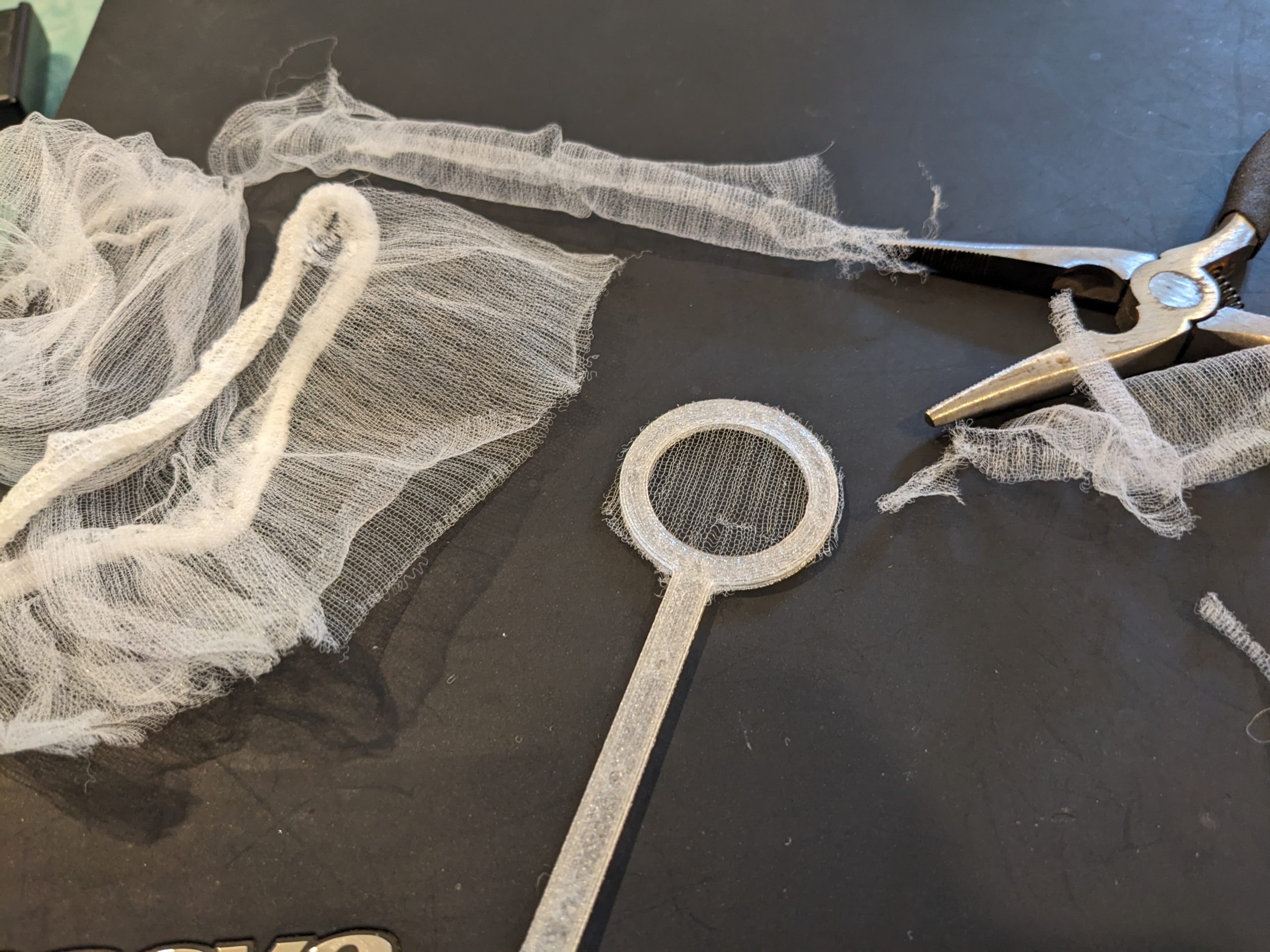
So, since most fish nets are way too big, I decided to DIY it with the 3D printer and some mesh material I had lying around, namely, kitchen sink strainer mesh bags.
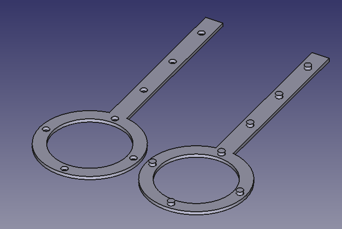
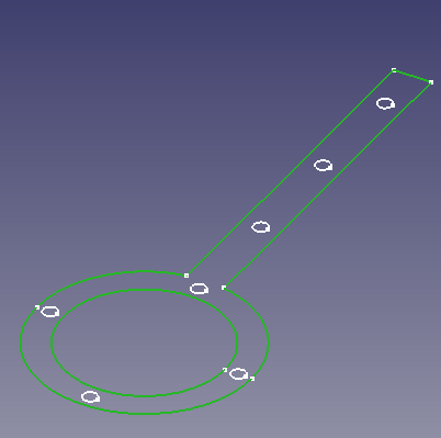
After buying the 3D printer (also about a month ago), I learned how to use FreeCAD. Making this 3D model took less than 10 minutes. Here’s how:
Use the arc tool to draw the round parts of the outer edge.
Use the line tool to draw the holder.
Use the circle tool to draw the inner hole.
Use the circle tool to draw the small holes (seen on the left side in the image above). I used a diameter of 2 mm.
Use distance constraints to space them evenly.
Apply “Pad”. I chose 1 mm.
If you’re satisfied with the result, duplicate the entire body (copy and paste).
Delete the padding in the new body. We will pad different parts of the sketch individually.
Select just the outer frame, like in the image below.
Pad by 1 mm.
Then select just the small circles, and pad by 2 mm.
You’re done!
You can now print out the file. Put the mesh material between the two parts of the holder, and use pliers to mate the protruding parts with the holes. (Bambu A1 Mini, standard 0.4 mm nozzle, bog-standard PLA, selected “precise wall” in OrcaSlicer. Your mileage may vary!) You may or may not need to use pliers (to create more force in a small spot) to mate the two parts of the holder together.
Like this, aight.
3D model
Here’s an archive with the .FCstd (FreeCAD) file and a .3mf file: