Wow, two weeks have passed since Christmas. Wow, we’re one week into 2024. Happy New Year!
I have an 8-year-old niece and I thought I’d give her an electronics kit for Christmas. Well, it seems that in modern electronics kits, electronic components are covered in a bunch of plastic, making everything look kind of childish. They are a little safer I suppose because they are too big to be swallowed. But at least I (as a child) didn’t really like stuff with a “Fisher-Price” look, I tended to want the real deal. So I decided to make my own electronics kit with my own manual! I just put in a few components I mostly had on hand (I also washed them before, just in case I’d used them somewhere dirty before):
- 5 red LEDs with a low forward voltage (around 1.7V), this way you can show that they light up (barely) with very fresh alkaline batteries. (Note: most red LEDs have a higher forward voltage of 1.85V or so, and wouldn’t light up at all)
- 5 blue LEDs
- 5 white LEDs
- 5 100 uF (or so) electrolytic capacitors
- 5 470 uF (or so) electrolytic capacitors
- 5 470 ohm (or so) resistors
- 5 2n2222 transistors
- 2 CR2032 batteries
- 2 CR2032 battery holders (the ones I bought can just barely fit into a breadboard)
- Optional: 4x AA/AAA battery holder and AA/AAA batteries (referenced in text, so make sure to remove reference if you don’t want to include them)
- Some wires
- 1 breadboard
I didn’t include a multimeter, but if the child’s/person’s household doesn’t have one, it might make sense to include one. (The manual doesn’t really fully explain how to use multimeters, however.)
In the manual, the first experiment makes use of the fact that blue and white LEDs have a forward voltage that is quite compatible with CR2032 coin cells. The experiment just sandwiches a coin cell between an LED’s legs.
Then the manual explains that this doesn’t work with red LEDs and a resistor is used to limit the current. (Actually it will probably be okay for a while because coin cells don’t give a lot of current.) Some effort is made to explain voltage, current, and resistance, but (hopefully) on a level that is (possibly, barely) understandable by an 8-year-old.
A little later, capacitors are explained a bit. And transistors. The final experiment is a circuit that has some twinkling LEDs. The following is a similar circuit, just to give you an idea:
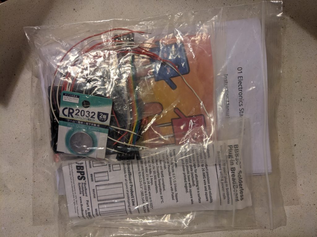
And here’s the completed set, just before wrapping it:

The manual is in .odt format (can be opened in LibreOffice and similar) and you can download it below. It includes some copyrighted pictures from other sites (the battery pic, the diode symbol(s), the transistor pic, the capacitor pic, and the empty breadboard pics). The front page image is AI-generated but heavily edited. Note: LibreOffice may have a bug that prevents emoji from being included in exported PDF files. My printed booklet ended up not containing emoji and I noticed only much later. :(
I made a booklet using the following LibreOffice print settings and a stapler:

If you want to customize the manual for somebody else, you should read through the entire thing. Edit it to your heart’s content. There is at least one reference to “8-year-olds”, maybe do a search. There are references to “dad or uncle” and “parents”. The “license” is “public domain”. Feel free to give credit, but you don’t have to.